EP1342627A2 - Bestimmung des Sitzbelegungsgewichts durch Verformung des Kissens - Google Patents
Bestimmung des Sitzbelegungsgewichts durch Verformung des Kissens Download PDFInfo
- Publication number
- EP1342627A2 EP1342627A2 EP03004488A EP03004488A EP1342627A2 EP 1342627 A2 EP1342627 A2 EP 1342627A2 EP 03004488 A EP03004488 A EP 03004488A EP 03004488 A EP03004488 A EP 03004488A EP 1342627 A2 EP1342627 A2 EP 1342627A2
- Authority
- EP
- European Patent Office
- Prior art keywords
- conductor
- intensity
- compliant pad
- seat
- oscillating signal
- Prior art date
- Legal status (The legal status is an assumption and is not a legal conclusion. Google has not performed a legal analysis and makes no representation as to the accuracy of the status listed.)
- Granted
Links
Images

Classifications
-
- B—PERFORMING OPERATIONS; TRANSPORTING
- B60—VEHICLES IN GENERAL
- B60R—VEHICLES, VEHICLE FITTINGS, OR VEHICLE PARTS, NOT OTHERWISE PROVIDED FOR
- B60R21/00—Arrangements or fittings on vehicles for protecting or preventing injuries to occupants or pedestrians in case of accidents or other traffic risks
- B60R21/01—Electrical circuits for triggering passive safety arrangements, e.g. airbags, safety belt tighteners, in case of vehicle accidents or impending vehicle accidents
- B60R21/015—Electrical circuits for triggering passive safety arrangements, e.g. airbags, safety belt tighteners, in case of vehicle accidents or impending vehicle accidents including means for detecting the presence or position of passengers, passenger seats or child seats, and the related safety parameters therefor, e.g. speed or timing of airbag inflation in relation to occupant position or seat belt use
- B60R21/01512—Passenger detection systems
- B60R21/01516—Passenger detection systems using force or pressure sensing means
-
- B—PERFORMING OPERATIONS; TRANSPORTING
- B60—VEHICLES IN GENERAL
- B60R—VEHICLES, VEHICLE FITTINGS, OR VEHICLE PARTS, NOT OTHERWISE PROVIDED FOR
- B60R21/00—Arrangements or fittings on vehicles for protecting or preventing injuries to occupants or pedestrians in case of accidents or other traffic risks
- B60R21/01—Electrical circuits for triggering passive safety arrangements, e.g. airbags, safety belt tighteners, in case of vehicle accidents or impending vehicle accidents
- B60R21/015—Electrical circuits for triggering passive safety arrangements, e.g. airbags, safety belt tighteners, in case of vehicle accidents or impending vehicle accidents including means for detecting the presence or position of passengers, passenger seats or child seats, and the related safety parameters therefor, e.g. speed or timing of airbag inflation in relation to occupant position or seat belt use
- B60R21/01512—Passenger detection systems
- B60R21/0153—Passenger detection systems using field detection presence sensors
- B60R21/01532—Passenger detection systems using field detection presence sensors using electric or capacitive field sensors
Definitions
- the present invention relates to vehicle sensors and, more specifically, to a vehicle sensor that determines the presence and weight of a seat occupant.
- the performance of an automotive air bag system in terms of its success or failure in preventing serious personal injury, may depend upon the size of the passenger present in the vehicle. For example, if the passenger is of relatively small size such as a child, the passenger may be seriously injured by the deployment of the air bag at full force. In another example, a passenger may not be present in the passenger side seat of a vehicle and in the event of an accident, a deployment of the airbag results in an unnecessary cost of repair. Therefore, it is desirable to measure the weight in the seat of an automobile to determine whether, in a crash, to deploy the airbag at full force, partial force, or simply not at all.
- Another solution uses a load cell at each of the four mounting points of the seat.
- the measurements from the four sensors are combined to find vehicle occupant weight.
- This system suffers from the difficulty of precisely matching the mounting planes of the seat and its base. Any mismatch in the seat mounting planes results in an error in the total weight measurement of the vehicle occupant.
- the system cost is high due to the need for multiple load cells of high precision, wiring and connectors for each load cell, and multiple sensing amplifiers.
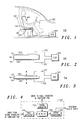
- one embodiment of the invention is an apparatus 100 for sensing the presence and weight of a vehicle occupant 106 in a vehicle 102 that includes a a seat 108 upon which the occupant 106 sits.
- An electronics unit 140 controls the apparatus 100 and includes an oscillating circuit that generates an oscillating signal having a first intensity.
- a compliant pad 110 is disposed within the seat 108 .
- the compliant pad 110 made be made of latex foam approximately one inch thick and is located so as to be compressed by the occupant 106 seated upon the seat 108 .
- the compliant pad 110 may also be made of other cushioning materials as is known in the art.
- a first conductor 120 is electrically coupled to the oscillating circuit and disposed adjacent to a first surface 112 of the compliant pad 110 .
- the first conductor 120 is connected to the electronics unit 140 by wire 122 .
- the first conductor 120 is capable of transmitting the oscillating signal at the first intensity.
- a second conductor 130 is disposed adjacent a second surface 114 spaced apart from the first surface 112 of the compliant pad 110 .
- the second conductor 130 is capable of receiving the oscillating signal at a second intensity.
- the distance between the first conductor 120 and second conductor 130 varies as the compliant pad 110 is compressed by the weight of the vehicle occupant 106 , which is represented by arrow W.
- the electronic unit 140 includes a detection circuit electrically coupled to the second conductor 130 which is capable of receiving the oscillating signal at the second intensity.
- the second conductor 130 is connected to the electronics unit 140 by wire 132 .
- the second intensity of the oscillating signal varies in relation to the distance between the first conductor 120 and the second conductor 130 .
- the first conductor 120 is forced closer to the second conductor 130 by the compression of the compliant pad 110 .
- the capacitive coupling between the two conductors 120, 130 is increased as the conductors are squeezed closer together.
- the second intensity of the oscillating signal increases due to the increase in the capacitive coupling between the conductors.
- the electronics unit 140 includes a signal generator module 142 , input amplifier module 144 , detector module 146 and signal processing module 148 .
- the signal generator module 142 generates an oscillating signal having a first intensity.
- the oscillating signal is applied to the first conductor 120 by wire 122 (as shown in FIGS. 2 and 3).
- the signal generator module 142 may be a sine wave generator, however many types of signal wave shape may be used.
- the input amplifier module 144 receives the oscillating signal at a second intensity from the second conductor 130 via wire 132 .
- the input amplifier module 144 amplifies the received signal and passes it to detector module 146 .
- the signal generator module 142 passes the oscillating signal at the first intensity to detector module 146 .
- the detector module 146 compares the oscillating signal intensity received from the signal generator module 142 and the oscillating signal intensity received from the input amplifier module 144 .
- the detector module 146 may be a synchronous detector.
- the signal processing module 148 receives the detection signal output of the detector module 146 and generates a signal proportionate to the weight of the vehicle occupant 106 by comparing the detection signal output of the detector module 146 to a known value.
- the electronics unit 140 is thus capable of determining the presence and weight of a vehicle occupant 106 .
- the mechanical properties and thickness of the compliant pad 110 , and the first intensity of the oscillating signal may be chosen to optimize the sensitivity of the apparatus 100 to be sensitive in the range of typical vehicle occupant 106 weights.
- the compliant pad 110 comprises a material having dielectric properties that vary with the compression of the compliant pad 110 .
- the second intensity varies as the compliant pad 110 is compressed in relation to both a change in the dielectric properties of the material, and the change in the distance between the first conductor 120 and the second conductor 130 .
- the compliant pad 110 could include latex foam as the dielectric cushioning material, or other materials as is known in the art.
- the latex foam material includes flexible latex solids and air trapped within the pockets or voids of the latex solids.
- the dielectric properties of the compliant pad 110 cross-section reflect both the dielectric properties of the flexible latex solids and the air entrapped within the latex solids.
- the capacitance between the first conductor 120 and second conductor 130 is a function of the spacing between the conductors, and the dielectric properties of the uncompressed latex foam material.
- the compliant pad 110 As the compliant pad 110 is compressed, the latex solids and the air contained within the pockets of the latex solids are squeezed together into a smaller volume changing the dielectric properties of the compliant pad cross-section.
- the capacitance between the conductors 120 and 130 increases as the compliant pad 110 is compressed due to both the decreased distance between the conductors and the change in dielectric properties of the compliant pad cross-section.
- the first conductor 120 is bonded to the first surface 112 of the compliant pad.
- the second conductor 130 is bonded to the second surface 114 of the compliant pad 110 .
- the wires 122 and 132 are routed through the vehicle seat 108 and interior compartment to the electronics unit 140.
- the first conductor 120 could be encased within the compliant pad 110, or the second conductor 130 could be encased within the compliant pad 110, or both conductors 120 and 130 may be encased within the compliant pad 110 .
- the first conductor 120 and second conductor 130 may include a conductive metal foil.
- the compliant pad 110 deflects according to the shape of the vehicle occupant 106 or object which is generating the load W.
- the conductive metal foil is flexible and conforms to the deflected shape of the compliant pad 110 as the load W is applied.
- the distance between the first conductor 120 and second conductor 130 will vary across the compliant pad 110 as each conductor is deflected into a 3-dinensional shape by the load W .
- the total capacitance between the two conductors 120, 130, as measured by the variation in the second intensity, will be a substantially accurate measurement of the total load W regardless of the shape of the vehicle occupant 106 or object applying the load.
- the first conductor 120 and second conductor 130 could include a conductive coating deposited upon surfaces 112 and 114 respectively of the compliant pad 110 .
- the conductive coating may be flexible and conform to the deflected shape of compliant pad 110 .
- the second conductor 130 includes a plurality of second conductors 134 distributed adjacent the second surface 114 of the compliant pad 110 with a plurality of individual second intensities measured at each conductor location.
- the plurality of individual second intensities measured at the plurality of second conductors 134 are used to characterize an object upon the seat.
- the object may be a vehicle occupant 106 or may merely be a package placed upon the seat.
- the electronics unit 140 receives the plurality of individual second intensities at a plurality of input amplifiers 144 .
- the detector module 146 then produces an output value for each of the individual second intensities.
- the signal processing module 148 uses an algorithm to determine if the plurality of detector module 146 output values represent the weight of a vehicle occupant 106 or an inanimate object. The signal processing module 148 then generates a signal indicating, in the event of a crash, whether to deploy the airbag and at what force.
- a guard conductor 150 is disposed between the second conductor 130 and the structure of the seat 152 .
- the structure of the seat 152 includes the metal frame of the seat and associated mounting hardware.
- the guard conductor 150 is made of conductive material and may have a periodic signal, corresponding to the periodic voltage of the oscillating signal, applied to it.
- the guard conductor 150 may be made of the same conductive material as the conductors 120 , 130 .
- An insulating layer 154 is positioned between the second conductor 130 and the guard conductor 150 to ensure the two conductors are precluded from direct electrical contact.
- a second insulating layer 156 is positioned between the guard conductor 150 and the structure of the seat 152.
- the insulating layers 154 , 156 may be made of Mylar sheet or another suitable insulator as is known in the art.
- an amplifier 160 is biased to provide a high impedance input from the second conductor 130 .
- the detection signal output of the amplifier 160 is sent to the detector module 146 and is also used to drive the corresponding guard conductor 150 with a low impedance signal having a frequency, phase, and amplitude corresponding to that of the sensed electrostatic signal.
- the high impedance input amplifier 160 is a voltage follower with 100% feedback to the inverting input. This configuration helps maximize input impedance. With this type of amplifier, common practice is to provide a diode clamp to supply and ground. However, in this high impedance application, the capacitance of the diodes would provide an undesirable load to the input signal. By using pairs of diodes for the clamps and driving the cathode-to-anode junctions with the guard drive signal, the diode capacitance effect is eliminated.
- a seated vehicle passenger may, upon fastening his seat belt, tighten the seat belt to a point where the vehicle occupant weight as determined by the apparatus 100 would be consistent with a heavier passenger.
- the problem may be avoided by using the "seat belt fastened" signal, as it is commonly known in the art, which is present when the seat belt clasp is engaged to terminate vehicle occupant weight measurement.
- the vehicle occupant weight that was detected before the seat belt clasp was fastened may be retained, thus avoiding the error introduced by tightening the seat belt.
Landscapes
- Engineering & Computer Science (AREA)
- Mechanical Engineering (AREA)
- Seats For Vehicles (AREA)
- Air Bags (AREA)
- Chair Legs, Seat Parts, And Backrests (AREA)
Applications Claiming Priority (2)
| Application Number | Priority Date | Filing Date | Title |
|---|---|---|---|
| US91214 | 2002-03-04 | ||
| US10/091,214 US6646452B2 (en) | 2002-03-04 | 2002-03-04 | Sensing of seat occupant weight by cushion deformation |
Publications (3)
| Publication Number | Publication Date |
|---|---|
| EP1342627A2 true EP1342627A2 (de) | 2003-09-10 |
| EP1342627A3 EP1342627A3 (de) | 2004-11-17 |
| EP1342627B1 EP1342627B1 (de) | 2008-04-16 |
Family
ID=27754004
Family Applications (1)
| Application Number | Title | Priority Date | Filing Date |
|---|---|---|---|
| EP03004488A Expired - Fee Related EP1342627B1 (de) | 2002-03-04 | 2003-02-28 | Bestimmung des Sitzbelegungsgewichts durch Verformung des Kissens |
Country Status (3)
| Country | Link |
|---|---|
| US (1) | US6646452B2 (de) |
| EP (1) | EP1342627B1 (de) |
| DE (1) | DE60320338T2 (de) |
Cited By (4)
| Publication number | Priority date | Publication date | Assignee | Title |
|---|---|---|---|---|
| WO2006015565A1 (de) * | 2004-08-13 | 2006-02-16 | Intedis Gmbh & Co. Kg | Kapazitive sensoreinrichtung |
| WO2006034756A1 (de) * | 2004-09-29 | 2006-04-06 | Daimlerchrysler Ag | Steuervorrichtung für ein insassenschutzmittel eines kraftfahrzeuges |
| FR2888789A1 (fr) * | 2005-07-20 | 2007-01-26 | Peugeot Citroen Automobiles Sa | Matelassure de siege de vehicule automobile et procede de realisation d'une telle matelassure |
| US7708101B2 (en) | 2005-01-24 | 2010-05-04 | F.S. Fehrer Automotive Gmbh | Motor vehicle seat having occupant detector |
Families Citing this family (30)
| Publication number | Priority date | Publication date | Assignee | Title |
|---|---|---|---|---|
| US20070135982A1 (en) | 1995-06-07 | 2007-06-14 | Automotive Technologies International, Inc. | Methods for Sensing Weight of an Occupying Item in a Vehicular Seat |
| US7523803B2 (en) * | 1995-06-07 | 2009-04-28 | Automotive Technologies International, Inc. | Weight determining systems and methods for vehicular seats |
| US6825765B2 (en) * | 1998-12-30 | 2004-11-30 | Automotive Systems Laboratory, Inc. | Occupant detection system |
| US7088113B2 (en) * | 2002-07-08 | 2006-08-08 | Intelligent Mechatronic Systems Inc. | Integrated occupant sensory system |
| US7258398B2 (en) * | 2003-06-26 | 2007-08-21 | Lear Corporation | Vehicle occupant sensing system having an upper slide member with an emitter interference member |
| US7132953B2 (en) | 2003-06-26 | 2006-11-07 | Lear Corporation | Spring sensor assembly for a vehicle seat cushion |
| US6994397B2 (en) * | 2003-06-26 | 2006-02-07 | Lear Corporation | Vehicle occupant sensing system having sensor assemblies with variable blasing member |
| US7172244B2 (en) * | 2003-06-26 | 2007-02-06 | Lear Corporation | Vehicle seat assembly having a vehicle occupant sensing system and a seat cushion insert positioned therein |
| US7063382B2 (en) * | 2003-06-26 | 2006-06-20 | Lear Corporation | Vehicle seat assembly having a vehicle occupant sensing system and a seat cushion insert |
| US7075450B2 (en) * | 2003-06-26 | 2006-07-11 | Lear Corporation | Vehicle occupant sensing system having discrete wiring |
| US6901322B1 (en) | 2003-12-30 | 2005-05-31 | Lear Corporation | Method of predicting an empty seat condition in an occupancy sensing system |
| US7034670B2 (en) * | 2003-12-30 | 2006-04-25 | Lear Corporation | Method of occupancy classification in a vehicle seat |
| US6985077B2 (en) * | 2003-12-30 | 2006-01-10 | Lear Corporation | Method of tuning a sensor array for occupancy sensing in a vehicle seat |
| US7185916B2 (en) * | 2004-01-14 | 2007-03-06 | Lear Corporation | Vehicle seat assembly having a field effect sensor for detecting seat position |
| US7225067B2 (en) * | 2004-07-02 | 2007-05-29 | Lear Corporation | Vehicle occupant sensing system for a vehicle seat assembly and method of operating the same |
| US7365278B2 (en) * | 2004-10-27 | 2008-04-29 | Lear Corporation | Vehicle occupant sensing system having a contamination barrier member |
| US7100980B2 (en) * | 2004-10-27 | 2006-09-05 | Lear Corporation | Vehicle seat assembly having a vehicle occupant sensing system with a biasing pad |
| US7405370B2 (en) * | 2004-10-27 | 2008-07-29 | Lear Corporation | Vehicle occupant sensing system having enclosed sensor assembly |
| US7428942B2 (en) * | 2004-10-27 | 2008-09-30 | Lear Corporation | Vehicle occupant sensing system having guiding ribs |
| US7402769B2 (en) * | 2004-10-27 | 2008-07-22 | Lear Corporation | Vehicle occupant sensing system having a retention member for a biasing member |
| US20060097497A1 (en) * | 2004-10-27 | 2006-05-11 | Sallam Faisal K | Vehicle occupant sensing system having a contamination barrier member |
| DE102006002919B4 (de) * | 2005-01-24 | 2008-09-04 | Denso Corp., Kariya | Kapazitiver Sensor und Insassenerfassungssystem |
| US7352191B2 (en) * | 2005-04-04 | 2008-04-01 | 3M Innovative Properties Company | Sensor assembly and method of forming the same |
| US7395717B2 (en) * | 2006-02-10 | 2008-07-08 | Milliken & Company | Flexible capacitive sensor |
| US7208960B1 (en) * | 2006-02-10 | 2007-04-24 | Milliken & Company | Printed capacitive sensor |
| US7301351B2 (en) * | 2006-02-10 | 2007-11-27 | Milliken & Company | Printed capacitive sensor |
| US7719007B2 (en) * | 2008-04-30 | 2010-05-18 | Milliken & Company | Flexible electroluminescent capacitive sensor |
| KR101774669B1 (ko) | 2015-12-09 | 2017-09-04 | 현대자동차주식회사 | 차량용 승객구분장치 |
| US10330813B2 (en) | 2017-07-11 | 2019-06-25 | Joyson Safety Systems Acquisition Llc | Occupant detection system |
| EP3725218B1 (de) * | 2017-12-15 | 2023-06-07 | Alps Alpine Co., Ltd. | Sensorvorrichtung, herstellungsverfahren dafür und fahrzeugsitz |
Family Cites Families (8)
| Publication number | Priority date | Publication date | Assignee | Title |
|---|---|---|---|---|
| US5232243A (en) * | 1991-04-09 | 1993-08-03 | Trw Vehicle Safety Systems Inc. | Occupant sensing apparatus |
| JPH05297149A (ja) * | 1992-04-23 | 1993-11-12 | Aisin Seiki Co Ltd | 誘電体検出装置 |
| WO1997029391A1 (en) * | 1996-02-09 | 1997-08-14 | Scandmec Ab | Device for sensing presence of an electrically conducting object |
| US6260879B1 (en) * | 1997-05-12 | 2001-07-17 | Automotive Systems Laboratory, Inc. | Air bag suppression system using a weight sensor, a seat belt tension monitor, and a capacitive sensor in the instrument panel |
| JP2000155057A (ja) | 1998-11-20 | 2000-06-06 | Asuko Kk | 着座検出装置 |
| US6520535B1 (en) | 1998-12-30 | 2003-02-18 | Automotive Systems Laboratory, Inc. | Occupant detection system |
| GB9919975D0 (en) * | 1999-08-24 | 1999-10-27 | Philipp Harald | Seat occupancy sensor for vehicular use |
| JP2001116614A (ja) * | 1999-09-07 | 2001-04-27 | Takata Corp | シート上の物体の判定方法及びエアバッグ展開モードの判定方法 |
-
2002
- 2002-03-04 US US10/091,214 patent/US6646452B2/en not_active Expired - Fee Related
-
2003
- 2003-02-28 DE DE60320338T patent/DE60320338T2/de not_active Expired - Lifetime
- 2003-02-28 EP EP03004488A patent/EP1342627B1/de not_active Expired - Fee Related
Non-Patent Citations (1)
| Title |
|---|
| None |
Cited By (4)
| Publication number | Priority date | Publication date | Assignee | Title |
|---|---|---|---|---|
| WO2006015565A1 (de) * | 2004-08-13 | 2006-02-16 | Intedis Gmbh & Co. Kg | Kapazitive sensoreinrichtung |
| WO2006034756A1 (de) * | 2004-09-29 | 2006-04-06 | Daimlerchrysler Ag | Steuervorrichtung für ein insassenschutzmittel eines kraftfahrzeuges |
| US7708101B2 (en) | 2005-01-24 | 2010-05-04 | F.S. Fehrer Automotive Gmbh | Motor vehicle seat having occupant detector |
| FR2888789A1 (fr) * | 2005-07-20 | 2007-01-26 | Peugeot Citroen Automobiles Sa | Matelassure de siege de vehicule automobile et procede de realisation d'une telle matelassure |
Also Published As
| Publication number | Publication date |
|---|---|
| US20030164715A1 (en) | 2003-09-04 |
| EP1342627B1 (de) | 2008-04-16 |
| DE60320338T2 (de) | 2009-05-20 |
| DE60320338D1 (de) | 2008-05-29 |
| EP1342627A3 (de) | 2004-11-17 |
| US6646452B2 (en) | 2003-11-11 |
Similar Documents
| Publication | Publication Date | Title |
|---|---|---|
| EP1342627B1 (de) | Bestimmung des Sitzbelegungsgewichts durch Verformung des Kissens | |
| EP1458588B1 (de) | Vorrichtung zur detektion der anwesenheit eines besetzers | |
| EP1427612B1 (de) | Insassenerfassung unter verwendung eines durch einen leiter erzeugten elektrischen felds | |
| US6161070A (en) | Passenger detection system | |
| US7159471B2 (en) | Capacitive load cell apparatus having silicone-impregnated foam dielectric pads | |
| US8237455B2 (en) | Occupant detection system with environmental compensation | |
| US7370883B2 (en) | Three dimensional occupant position sensor | |
| KR100921484B1 (ko) | 좌석 점유자 검출 방법 및 검출용 센서 시스템 | |
| US6696948B2 (en) | Wet seat protection for air bag control occupant detection | |
| US20070241895A1 (en) | Noise reduction for flexible sensor material in occupant detection | |
| US20050043876A1 (en) | Fluid filled seat bladder with capacitive sensors for occupant classification and weight estimation | |
| US20020018000A1 (en) | Passenger detection system | |
| KR20020070848A (ko) | 에어백 전개 제어를 위한 다중 센서 차량 점유자 검출 | |
| WO1998022836A1 (en) | Device for presence detection | |
| US20110029203A1 (en) | Occupant classification system | |
| US20080277910A1 (en) | Vehicle seat including sensor | |
| US20110163767A1 (en) | Occupant detection system and method | |
| US6644126B2 (en) | Sensor device for detecting mechanical deformation | |
| US6437695B1 (en) | Method for capacitive object recognition in vehicles | |
| US7373845B2 (en) | Seat belt tension sensor | |
| JP2005526666A (ja) | 乗員検出システム | |
| JP3322297B2 (ja) | 乗員検知システム及び乗員検知方法 | |
| US20040114465A1 (en) | System for classifying occupants of a vehicle | |
| WO2012135303A1 (en) | Occupant classification system |
Legal Events
| Date | Code | Title | Description |
|---|---|---|---|
| PUAI | Public reference made under article 153(3) epc to a published international application that has entered the european phase |
Free format text: ORIGINAL CODE: 0009012 |
|
| AK | Designated contracting states |
Kind code of ref document: A2 Designated state(s): AT BE BG CH CY CZ DE DK EE ES FI FR GB GR HU IE IT LI LU MC NL PT SE SI SK TR |
|
| AX | Request for extension of the european patent |
Extension state: AL LT LV MK RO |
|
| PUAL | Search report despatched |
Free format text: ORIGINAL CODE: 0009013 |
|
| AK | Designated contracting states |
Kind code of ref document: A3 Designated state(s): AT BE BG CH CY CZ DE DK EE ES FI FR GB GR HU IE IT LI LU MC NL PT SE SI SK TR |
|
| AX | Request for extension of the european patent |
Extension state: AL LT LV MK RO |
|
| 17P | Request for examination filed |
Effective date: 20050307 |
|
| AKX | Designation fees paid |
Designated state(s): DE GB |
|
| RIC1 | Information provided on ipc code assigned before grant |
Ipc: B60R 21/015 20060101AFI20070709BHEP |
|
| GRAP | Despatch of communication of intention to grant a patent |
Free format text: ORIGINAL CODE: EPIDOSNIGR1 |
|
| GRAS | Grant fee paid |
Free format text: ORIGINAL CODE: EPIDOSNIGR3 |
|
| GRAA | (expected) grant |
Free format text: ORIGINAL CODE: 0009210 |
|
| AK | Designated contracting states |
Kind code of ref document: B1 Designated state(s): DE GB |
|
| REF | Corresponds to: |
Ref document number: 60320338 Country of ref document: DE Date of ref document: 20080529 Kind code of ref document: P |
|
| PLBE | No opposition filed within time limit |
Free format text: ORIGINAL CODE: 0009261 |
|
| STAA | Information on the status of an ep patent application or granted ep patent |
Free format text: STATUS: NO OPPOSITION FILED WITHIN TIME LIMIT |
|
| 26N | No opposition filed |
Effective date: 20090119 |
|
| PGFP | Annual fee paid to national office [announced via postgrant information from national office to epo] |
Ref country code: GB Payment date: 20130218 Year of fee payment: 11 Ref country code: DE Payment date: 20130228 Year of fee payment: 11 |
|
| REG | Reference to a national code |
Ref country code: DE Ref legal event code: R119 Ref document number: 60320338 Country of ref document: DE |
|
| GBPC | Gb: european patent ceased through non-payment of renewal fee |
Effective date: 20140228 |
|
| REG | Reference to a national code |
Ref country code: DE Ref legal event code: R119 Ref document number: 60320338 Country of ref document: DE Effective date: 20140902 |
|
| PG25 | Lapsed in a contracting state [announced via postgrant information from national office to epo] |
Ref country code: DE Free format text: LAPSE BECAUSE OF NON-PAYMENT OF DUE FEES Effective date: 20140902 Ref country code: GB Free format text: LAPSE BECAUSE OF NON-PAYMENT OF DUE FEES Effective date: 20140228 |