EP1342575B1 - Dispositif pour nettoyer un rouleau ou un cylindre - Google Patents
Dispositif pour nettoyer un rouleau ou un cylindre Download PDFInfo
- Publication number
- EP1342575B1 EP1342575B1 EP03101552A EP03101552A EP1342575B1 EP 1342575 B1 EP1342575 B1 EP 1342575B1 EP 03101552 A EP03101552 A EP 03101552A EP 03101552 A EP03101552 A EP 03101552A EP 1342575 B1 EP1342575 B1 EP 1342575B1
- Authority
- EP
- European Patent Office
- Prior art keywords
- cleaning
- roller
- toothed belt
- elements
- carrier
- Prior art date
- Legal status (The legal status is an assumption and is not a legal conclusion. Google has not performed a legal analysis and makes no representation as to the accuracy of the status listed.)
- Expired - Lifetime
Links
- 238000004140 cleaning Methods 0.000 title claims abstract description 55
- 230000002093 peripheral effect Effects 0.000 claims abstract 2
- 238000007639 printing Methods 0.000 claims description 6
- 239000012459 cleaning agent Substances 0.000 description 13
- 239000003599 detergent Substances 0.000 description 8
- 238000000034 method Methods 0.000 description 6
- 230000000694 effects Effects 0.000 description 4
- 239000012535 impurity Substances 0.000 description 3
- 239000007788 liquid Substances 0.000 description 3
- 238000011109 contamination Methods 0.000 description 2
- 238000007791 dehumidification Methods 0.000 description 2
- 239000012530 fluid Substances 0.000 description 2
- 239000003973 paint Substances 0.000 description 2
- 238000010408 sweeping Methods 0.000 description 2
- 230000004323 axial length Effects 0.000 description 1
- 238000007664 blowing Methods 0.000 description 1
- 238000010276 construction Methods 0.000 description 1
- 230000008021 deposition Effects 0.000 description 1
- 230000002441 reversible effect Effects 0.000 description 1
- 239000000344 soap Substances 0.000 description 1
- 239000002904 solvent Substances 0.000 description 1
- 238000005507 spraying Methods 0.000 description 1
- XLYOFNOQVPJJNP-UHFFFAOYSA-N water Substances O XLYOFNOQVPJJNP-UHFFFAOYSA-N 0.000 description 1
- 238000009736 wetting Methods 0.000 description 1
Images
Classifications
-
- B—PERFORMING OPERATIONS; TRANSPORTING
- B41—PRINTING; LINING MACHINES; TYPEWRITERS; STAMPS
- B41F—PRINTING MACHINES OR PRESSES
- B41F35/00—Cleaning arrangements or devices
-
- B—PERFORMING OPERATIONS; TRANSPORTING
- B41—PRINTING; LINING MACHINES; TYPEWRITERS; STAMPS
- B41P—INDEXING SCHEME RELATING TO PRINTING, LINING MACHINES, TYPEWRITERS, AND TO STAMPS
- B41P2235/00—Cleaning
- B41P2235/10—Cleaning characterised by the methods or devices
- B41P2235/20—Wiping devices
-
- B—PERFORMING OPERATIONS; TRANSPORTING
- B41—PRINTING; LINING MACHINES; TYPEWRITERS; STAMPS
- B41P—INDEXING SCHEME RELATING TO PRINTING, LINING MACHINES, TYPEWRITERS, AND TO STAMPS
- B41P2235/00—Cleaning
- B41P2235/10—Cleaning characterised by the methods or devices
- B41P2235/20—Wiping devices
- B41P2235/23—Brushes
-
- B—PERFORMING OPERATIONS; TRANSPORTING
- B41—PRINTING; LINING MACHINES; TYPEWRITERS; STAMPS
- B41P—INDEXING SCHEME RELATING TO PRINTING, LINING MACHINES, TYPEWRITERS, AND TO STAMPS
- B41P2235/00—Cleaning
- B41P2235/10—Cleaning characterised by the methods or devices
- B41P2235/26—Spraying devices
Definitions
- the invention relates to a device for cleaning a roller or a cylinder according to the preamble of claim 1.
- a device for cleaning of rollers in which a rotatable brush roller by hand on the roller to be cleaned can be guided along, wherein a cleaning liquid can be applied to the brush roller.
- This known device includes a reservoir for the cleaning fluid and a collecting container for the dirt to be removed.
- a device for developing cylindrical surfaces in which a brush roller for cleaning the cylindrical surface in the longitudinal direction of the roller is movable.
- US 5 568 768 A, US 5 255 606 A, DE 25 22 743 A1, DE 23 17 174 B2, US 2 171 631 A and DE-AS 1 561 029 disclose devices for cleaning rolls with a in the longitudinal direction of the rollers rotating cleaning element.
- the invention has for its object to provide a device for cleaning a roller or a cylinder.
- the achievable with the present invention consist in particular in that a high and reliable cleaning effect can be achieved with a relatively simple construction of the device, wherein a particular liquid detergent Can be used.
- the cleaning agent can be reprocessed and circulated, at the same time enabling self-cleaning of the device.
- the device according to the invention can permanently remain in a fixed position relative to the roller to be cleaned, whereby cost-intensive set-up times can be avoided.
- Another advantage is that the cleaning effect of the device according to the invention can be adapted in a simple manner to the degree of contamination of the roller to be cleaned.
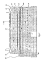
- the device 01 according to the invention is arranged in the immediate vicinity of a roller 02 or cylinder to be cleaned, for example a forme cylinder or a guide roller of a printing press (not shown).
- the device 01 initially has a first carrier element 03 in the form of a toothed belt, which is guided over two axially spaced rotatable guide elements in the form of pulleys 04 and 05 respectively.
- a loop-like endlessly circulating carrier element is formed with a first strand 06 facing the roll 02 and a second strand 07 facing away from the roll.
- an unillustrated drive acts on at least one of the pulleys 04 or 05 with a torque and thus causes a drive of the toothed belt 03 in the direction F of a longitudinal axis of the roller 02.
- the two pulleys 04 and 05 more precisely their perpendicular to the plane extending center axes 08 and 09, have an axial distance, which in the illustrated embodiment substantially corresponds to the axial length of the roller to be cleaned 02.
- the toothed belt 03 is provided with cleaning elements 10 in the form of bristle-like bristle elements, which are arranged on the toothed belt 03, that they radially outward, based on the loop formed by the toothed belt 03, point.
- the timing belt 03 is not provided over its entire length with bristle elements 10; rather, the timing belt is only bristled 03 over half its length.
- the toothed belt 03 can be brought from a position where a part or substantially all of the bristle elements 10 engage with the surface of the roller 02 to be cleaned or abutted thereto (working position) to the position shown in FIG be, in which all the bristle elements 10 are located on the side facing away from the roller 02 strand 07 (rest position).
- the device 01 In the region of the path 02 leading away from the roller 02, the device 01 is provided with a series of cleaning chambers 11, 12, 13, 14 and 15 arranged one behind the other, which are successively passed through by the toothed belt 03 and thus the bristle elements 10.
- the bristle elements 10 are at least partially released from the surface of the roller 02 recorded impurities. This can be achieved, for example, by scrapers, not shown, or at least supported, which are arranged in the respective cleaning chambers.
- each cleaning chamber 11, 12, 13, 14 and 15 has an inlet 16 for a cleaning agent for cleaning the bristle elements 10.
- a cleaning agent may be a cleaning liquid, for example water, optionally also with the addition of solvents, soaps, alkalis or the like, use.
- the cleaning agent is rinsed into the cleaning chambers 11, 12, 13, 14 and 15, wherein the guided through the cleaning chambers bristle elements 10 are wetted and freed of their pollution load.
- each cleaning chamber 11, 12, 13, 14 and 15 has a drain 17 for the after cleaning the bristle elements 10 soiled cleaning agent.
- a further chamber 18 is arranged, which is also traversed by the toothed belt 03 and the bristle elements 10.
- this chamber 18 in which no detergent is supplied, there is a targeted dehumidification of the bristle elements 10 except for a predetermined depending on the particular application degree. In this case, this dehumidification, for example, by a not shown scraper, which comes into engagement with the bristle elements 10, or by blowing compressed air or the like.
- the stripped or blown detergent is removed from the chamber 18 through a drain 19.
- the drains 17 of the cleaning chambers 11, 12, 13, 14 and 15 and the outlet 19 of the chamber 18 open into a common collecting channel 20.
- the collecting channel 20 is connected via a line 21 to a collecting vessel 22, in FIG which the polluted cleaning agent is passed.
- the contaminated cleaning agent is guided in or after the collecting vessel 22 through a filter element 23 and cleaned there of the impurities.
- the so-recycled and optionally post-dosed detergent is stored in a second collecting vessel 24 and from there by means of a pump 25 and a line 26 again via the feeds 16 into the cleaning chambers 11, 12, 13, 14 and 15. Overall, therefore, a substantially closed detergent circuit can be realized.
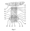
- two toothed belts 03 and 27 are arranged one behind the other with respect to the circumferential direction of the roller 02, ie. H. arranged one above the other.
- the second toothed belt 27 is provided in the same way as the first toothed belt 03 over its half length with bristle elements 28.
- the toothed belt 27 is guided in basically the same way as the toothed belt 03 via pulleys, not shown, whose center axes are aligned with the center axes 08 and 09 of the pulleys 04 and 05.
- At least one of the pulleys of the toothed belt 27 has a drive, with which this pulley with a torque for driving the toothed belt 27 can be acted upon.
- the drive of the toothed belt 03 and the drive of the toothed belt 27 are basically independent. In the embodiment shown here, the drive of the toothed belt 03 and the drive of the toothed belt 27 are in opposite directions, so that the direction of rotation of the pulleys and thus the timing belt 03 and 27 are even in opposite directions. The directions of rotation of the drives can be reversible.
- a guide member 29 is provided between the pulleys 04 and 05 of the belt 03 and the pulleys, not shown, which extends in the illustrated embodiment, substantially over the entire gap between the respective pulleys.
- the guide member 29 has on both sides superimposed groove-like depressions 30, 31 and 32, 33, in which the respective runs of the toothed belts 03 and 27 are guided. This is done both a Guide perpendicular to the main belt formed by the belt loops levels as well as a support of the timing belt 03 and 27 against the groove bottom.
- a component 34 is arranged on the guide member 29 in which the cleaning chambers 11, 12, 13, 14 and 15 and the chamber 18 for the upper toothed belt 03 and, in principle, the same Way, the cleaning chambers 35 and the chamber for the lower timing belt 27 are formed. All chambers open with their sequence 17 or 19 (upper toothed belt 03) and 36 (lower toothed belt 27) in the common collecting channel 20, which is also formed directly in the component 34.
- the inlets 16 (upper toothed belt 03) and 37 (lower toothed belt 27) for the inflow of cleaning agent, the cleaning chamber 11, 12, 13, 14 and 15 and 35 are further arranged.
- the inlets 16 and 37 open into laterally above and below the component 34 scheduled manifolds 38 and 39, which are supplied via the line 26 of pump 25 with detergent.
- the roller 02 to be cleaned has on its surface a plate 40 for flexographic printing, which is to be freed after a designated ended printing process of impurities, especially paint residues.
- the bristle elements 10 and 28 are arranged on the side facing away from the roller 02 run of the toothed belt 03 and 27, so that no interference with the roller 02 and at the flexographic Plate 40 is done.
- the distance of the device 01 from the roller 02 is selected so that in the working position, ie with the Bristle elements 10 provided run of the toothed belt now points to the roller 02, the bristle elements with the roll surface in mechanical engagement or on the roll surface can come to rest.
- the device 01 according to the invention can remain in the same position on the roller during the printing process, so that expensive set-up times are eliminated.
- the cleaning chambers 11, 12, 13, 14 and 15 are rinsed with cleaning fluid, thereby wetting the bristle elements 10.
- the bristle elements 10 move through the chambers arranged one behind the other and, after rinsing with cleaning agents in the cleaning chambers 11, 12, 13, 14 and 15 wetted bristle elements 10 in the second chamber 19 just dehumidified so far that for a Sweeping the roll surface undesirably leakage of cleaning agent from the gap between the roller 02 and the device 01 is largely prevented, on the other hand, however, when sweeping the arranged on the roll surface plate 40 with the bristle elements 10 a sufficient amount of detergent is transferred to the plate to soften the paint to be removed by the cleaning process.
- the bristle elements 10 initially carry out both a transfer of cleaning agent to the surface to be cleaned and a mechanically abrasive removal of the dirt. With increasing release of the residual moisture of the bristle elements 10 on the surface of the roller 02 and the flexographic plate 40, the bristle elements 10 are able to absorb the ink residues from the roll surface and the rinsing in the Release cleaning chambers 11, 12, 13, 14 and 15 for deposition.
- the cycle time ie in particular the residence time and amount of the cleaning agent on the roll surface, in particular by adjusting the rotational speed of the roller 02 and the rotational speed of the toothed belt, but also by adjusting the residual moisture content of the bristle elements 10 in the chamber 18 in dependence, for example, on the degree of contamination in freely adjustable over wide limits.
- a second toothed belt 27 which acts in basically the same way, but is driven in opposite directions to the toothed belt 03, in particular the cleaning surface can be increased and thereby the cleaning time can be shortened. Due to the opposite movement of the two toothed belts 03 and 27 also subject in the direction of movement of the timing belt 03 and 27 flanks of the intended elevations and / or depressions of the roll surface of a more uniform cleaning effect, since "shadow areas" are largely prevented.
- the device 01 is further provided with a housing 41 which is open to the roller 02.
- the edge regions of the housing 41 in the region of both end faces of the roller 02 have splash plates 42 and 43, which, depending on the direction of rotation of the toothed belt 03 and 27, an uncontrolled spraying of detergent at the exit of the bristle elements 10 from the chamber 18 and from dirty Prevent cleaning agent when entering the bristle elements 10 in the housing 41.
Landscapes
- Inking, Control Or Cleaning Of Printing Machines (AREA)
- Rolls And Other Rotary Bodies (AREA)
- Cleaning In General (AREA)
Claims (8)
- Dispositif pour nettoyer un rouleau (02) ou un cylindre, présentant au moins un élément de nettoyage (10; 28), déplaçable essentiellement en direction longitudinale du rouleau (02) à nettoyer, sur celui-ci, l'élément de nettoyage (10; 28) étant disposé sur un élément support (03; 27) tournant sensiblement dans la direction longitudinale du rouleau (02), et l'élément support (03; 27) présentant un tronçon (06) tourné vers le rouleau (02), et un tronçon (07) écarté du rouleau (02), caractérisé en ce que l'élément support (03, 27) présente, dans la direction de circulation, uniquement en partie, des éléments de nettoyage (10; 28), et en ce que, en une position de repos, tous les éléments de nettoyage (10; 28) sont disposés sur le tronçon (07) écarté du rouleau (02).
- Dispositif selon la revendication 1, caractérisé en ce que l'élément de nettoyage (10; 28) est réalisé à la façon d'une brosse ou à la façon d'une tête de brosse.
- Dispositif selon la revendication 1, caractérisé en ce que l'élément support (03; 27) est réalisé à la façon d'une bande, d'une chaîne ou d'une courroie.
- Dispositif selon la revendication 3, caractérisé en ce que l'élément support (03; 27) est réalisé à la façon d'une courroie dentée.
- Dispositif selon la revendication 1, caractérisé en ce que l'élément support (03; 27) est guidé, sur les deux extrémités axiales, sur des éléments de guidage (04; 05), du genre de rouleaux, de poulies ou disques, ou de roues dentées, au moins l'un de ces éléments de guidage (04; 05) étant susceptible d'être entraîné.
- Dispositif selon la revendication 5, caractérisé en ce que, entre les éléments de guidage (04; 05), opposés l'un à l'autre, des éléments supports (03; 27) est prévu un guidage d'élément support (29), dans lequel les éléments supports (03; 27) sont guidés, au moins par tronçons, et sont soutenus par rapport au rouleau (02) à nettoyer.
- Dispositif selon la revendication 1, caractérisé en ce que le tronçon (07) écarté du rouleau (02) passe, au moins par tronçons, par au moins une chambre de nettoyage (11, 12, 13, 14, 15), dans laquelle l'élément de nettoyage (10, 28) est soumis à un processus de nettoyage.
- Dispositif selon la revendication 1, caractérisé en ce que les rouleaux (02) ou les cylindres sont disposés dans une machine à imprimer rotative.
Applications Claiming Priority (3)
| Application Number | Priority Date | Filing Date | Title |
|---|---|---|---|
| DE10009353A DE10009353A1 (de) | 2000-02-28 | 2000-02-28 | Vorrichtung zum Reinigen einer Walze oder eines Zylinders |
| DE10009353 | 2000-02-28 | ||
| EP01913556A EP1259379B1 (fr) | 2000-02-28 | 2001-02-01 | Dispositif pour nettoyer un rouleau ou un cylindre |
Related Parent Applications (2)
| Application Number | Title | Priority Date | Filing Date |
|---|---|---|---|
| EP01913556.5 Division | 2001-02-01 | ||
| EP01913556A Division EP1259379B1 (fr) | 2000-02-28 | 2001-02-01 | Dispositif pour nettoyer un rouleau ou un cylindre |
Publications (3)
| Publication Number | Publication Date |
|---|---|
| EP1342575A2 EP1342575A2 (fr) | 2003-09-10 |
| EP1342575A3 EP1342575A3 (fr) | 2003-09-24 |
| EP1342575B1 true EP1342575B1 (fr) | 2006-08-02 |
Family
ID=7632708
Family Applications (3)
| Application Number | Title | Priority Date | Filing Date |
|---|---|---|---|
| EP01913556A Expired - Lifetime EP1259379B1 (fr) | 2000-02-28 | 2001-02-01 | Dispositif pour nettoyer un rouleau ou un cylindre |
| EP03101552A Expired - Lifetime EP1342575B1 (fr) | 2000-02-28 | 2001-02-01 | Dispositif pour nettoyer un rouleau ou un cylindre |
| EP03101554A Expired - Lifetime EP1342576B1 (fr) | 2000-02-28 | 2001-02-01 | Dispositif pour nettoyer un rouleau ou un cylindre |
Family Applications Before (1)
| Application Number | Title | Priority Date | Filing Date |
|---|---|---|---|
| EP01913556A Expired - Lifetime EP1259379B1 (fr) | 2000-02-28 | 2001-02-01 | Dispositif pour nettoyer un rouleau ou un cylindre |
Family Applications After (1)
| Application Number | Title | Priority Date | Filing Date |
|---|---|---|---|
| EP03101554A Expired - Lifetime EP1342576B1 (fr) | 2000-02-28 | 2001-02-01 | Dispositif pour nettoyer un rouleau ou un cylindre |
Country Status (5)
| Country | Link |
|---|---|
| EP (3) | EP1259379B1 (fr) |
| AT (3) | ATE334826T1 (fr) |
| AU (1) | AU2001239151A1 (fr) |
| DE (4) | DE10009353A1 (fr) |
| WO (1) | WO2001064440A1 (fr) |
Family Cites Families (6)
| Publication number | Priority date | Publication date | Assignee | Title |
|---|---|---|---|---|
| US2171631A (en) * | 1935-07-08 | 1939-09-05 | Celanese Corp | Device for cleaning rotating cylinders |
| US3411444A (en) * | 1966-04-22 | 1968-11-19 | Oxy Dry Internat Ltd | Blanket washing apparatus for use with printing presses |
| JPH03288756A (ja) * | 1990-04-02 | 1991-12-18 | Tokyo Kikai Seisakusho Ltd | ドラッグローラー装置 |
| DE4426079A1 (de) * | 1994-07-22 | 1996-01-25 | Baldwin Gegenheimer Gmbh | Gerät zur Reinigung von Walzen |
| US5568768A (en) * | 1995-05-04 | 1996-10-29 | Presstek, Inc. | Cleaning apparatus for offset plates |
| DE19734103B4 (de) * | 1997-08-07 | 2008-08-07 | Koenig & Bauer Aktiengesellschaft | Einrichtung zum Entwickeln von zylindrischen Oberflächen |
-
2000
- 2000-02-28 DE DE10009353A patent/DE10009353A1/de not_active Withdrawn
-
2001
- 2001-02-01 AT AT03101554T patent/ATE334826T1/de not_active IP Right Cessation
- 2001-02-01 EP EP01913556A patent/EP1259379B1/fr not_active Expired - Lifetime
- 2001-02-01 DE DE50110645T patent/DE50110645D1/de not_active Expired - Fee Related
- 2001-02-01 DE DE50110646T patent/DE50110646D1/de not_active Expired - Fee Related
- 2001-02-01 EP EP03101552A patent/EP1342575B1/fr not_active Expired - Lifetime
- 2001-02-01 AT AT01913556T patent/ATE253458T1/de not_active IP Right Cessation
- 2001-02-01 AT AT03101552T patent/ATE334825T1/de not_active IP Right Cessation
- 2001-02-01 DE DE50100904T patent/DE50100904D1/de not_active Expired - Fee Related
- 2001-02-01 EP EP03101554A patent/EP1342576B1/fr not_active Expired - Lifetime
- 2001-02-01 WO PCT/DE2001/000385 patent/WO2001064440A1/fr not_active Ceased
- 2001-02-01 AU AU2001239151A patent/AU2001239151A1/en not_active Abandoned
Also Published As
| Publication number | Publication date |
|---|---|
| EP1259379A1 (fr) | 2002-11-27 |
| EP1342575A2 (fr) | 2003-09-10 |
| ATE334826T1 (de) | 2006-08-15 |
| AU2001239151A1 (en) | 2001-09-12 |
| DE50110646D1 (de) | 2006-09-14 |
| DE50100904D1 (de) | 2003-12-11 |
| ATE253458T1 (de) | 2003-11-15 |
| ATE334825T1 (de) | 2006-08-15 |
| EP1342576A2 (fr) | 2003-09-10 |
| EP1259379B1 (fr) | 2003-11-05 |
| DE50110645D1 (de) | 2006-09-14 |
| WO2001064440A1 (fr) | 2001-09-07 |
| DE10009353A1 (de) | 2001-09-20 |
| EP1342576B1 (fr) | 2006-08-02 |
| EP1342576A3 (fr) | 2003-09-24 |
| EP1342575A3 (fr) | 2003-09-24 |
Similar Documents
| Publication | Publication Date | Title |
|---|---|---|
| DE2815388C3 (de) | Vorrichtung zum Waschen von Zylindern an Druckmaschinen, insbesondere Offsetdruckmaschinen | |
| EP0963927A2 (fr) | Dispositif et procédé pour nettoyer des bandes transporteuses | |
| DE69718007T2 (de) | Vorrichtung und verfahren zum reinigen von flexographischen druckplatten | |
| EP0693378B1 (fr) | Appareil pour nettoyer des cylindres | |
| EP0520305B1 (fr) | Dispositif de nettoyage pour systèmes d'encrage de machines à imprimer | |
| EP0919381B1 (fr) | Dispositif de nettoyage d'un cylindre dans une machine d'impression | |
| DE4443356C2 (de) | Verfahren zur Reinigung eines Zylinders einer Rotationsdruckmaschine | |
| EP1342575B1 (fr) | Dispositif pour nettoyer un rouleau ou un cylindre | |
| EP1023996A2 (fr) | Système de lavage à l'extérieur d'une machine d'impression pour blanchets en caoutchouc en forme de boites | |
| DE4233953A1 (de) | Druckmaschinenzylinder-Waschvorrichtung | |
| DE2124085A1 (fr) | ||
| WO2006018165A1 (fr) | Machine-outil, machine de laminage a froid et procede de nettoyage de zones de machines-outils | |
| DE19601070A1 (de) | Verfahren und Vorrichtung zum Waschen von Druckmaschinen-Zylindern | |
| DE19931305A1 (de) | Reinigungsvorrichtung für das Druckwerk einer Rotationsdruckmaschine | |
| DE102008004073B4 (de) | Vorrichtung zum Reinigen von Zylindern einer Druckmaschine | |
| DE202006015429U1 (de) | Vorrichtung zum Reinigen eines Druckzylinders | |
| EP1188559A1 (fr) | Dispositif pour la formation d'images sur des surfaces cylindriques dans des machines d'impression | |
| DE10027023B4 (de) | Vorrichtungen zur Reinigung einer Walze oder eines Zylinders | |
| DE3929282C2 (fr) | ||
| EP0909648B1 (fr) | Dispositif de nettoyage des cylindres d'une presse à imprimer | |
| DE10112756A1 (de) | Filmfarbwerk in einer Druckmaschine und verfahren zu dessen Reinigung | |
| DE19702791A1 (de) | Vorrichtung zum Reinigen eines Transportbandes | |
| DE102005000788B4 (de) | Farbwerk einer Rotationsdruckmaschine | |
| DE10027021B4 (de) | Vorrichtung zur Reinigung einer Walze oder eines Zylinders | |
| EP0770483A2 (fr) | Dispositif de nettoyage pour nettoyer des cylindres d'un appareil à imprimer offset |
Legal Events
| Date | Code | Title | Description |
|---|---|---|---|
| PUAI | Public reference made under article 153(3) epc to a published international application that has entered the european phase |
Free format text: ORIGINAL CODE: 0009012 |
|
| PUAL | Search report despatched |
Free format text: ORIGINAL CODE: 0009013 |
|
| AC | Divisional application: reference to earlier application |
Ref document number: 1259379 Country of ref document: EP Kind code of ref document: P |
|
| AK | Designated contracting states |
Kind code of ref document: A2 Designated state(s): AT BE CH CY DE DK ES FI FR GB GR IE IT LI LU MC NL PT SE TR |
|
| AK | Designated contracting states |
Kind code of ref document: A3 Designated state(s): AT BE CH CY DE DK ES FI FR GB GR IE IT LI LU MC NL PT SE TR |
|
| 17P | Request for examination filed |
Effective date: 20030809 |
|
| AKX | Designation fees paid |
Designated state(s): AT BE CH CY DE DK ES FI FR GB GR IE IT LI LU MC NL PT SE TR |
|
| GRAP | Despatch of communication of intention to grant a patent |
Free format text: ORIGINAL CODE: EPIDOSNIGR1 |
|
| GRAS | Grant fee paid |
Free format text: ORIGINAL CODE: EPIDOSNIGR3 |
|
| GRAA | (expected) grant |
Free format text: ORIGINAL CODE: 0009210 |
|
| AC | Divisional application: reference to earlier application |
Ref document number: 1259379 Country of ref document: EP Kind code of ref document: P |
|
| AK | Designated contracting states |
Kind code of ref document: B1 Designated state(s): AT BE CH CY DE DK ES FI FR GB GR IE IT LI LU MC NL PT SE TR |
|
| PG25 | Lapsed in a contracting state [announced via postgrant information from national office to epo] |
Ref country code: IT Free format text: LAPSE BECAUSE OF FAILURE TO SUBMIT A TRANSLATION OF THE DESCRIPTION OR TO PAY THE FEE WITHIN THE PRESCRIBED TIME-LIMIT;WARNING: LAPSES OF ITALIAN PATENTS WITH EFFECTIVE DATE BEFORE 2007 MAY HAVE OCCURRED AT ANY TIME BEFORE 2007. THE CORRECT EFFECTIVE DATE MAY BE DIFFERENT FROM THE ONE RECORDED. Effective date: 20060802 Ref country code: FI Free format text: LAPSE BECAUSE OF FAILURE TO SUBMIT A TRANSLATION OF THE DESCRIPTION OR TO PAY THE FEE WITHIN THE PRESCRIBED TIME-LIMIT Effective date: 20060802 Ref country code: IE Free format text: LAPSE BECAUSE OF FAILURE TO SUBMIT A TRANSLATION OF THE DESCRIPTION OR TO PAY THE FEE WITHIN THE PRESCRIBED TIME-LIMIT Effective date: 20060802 Ref country code: NL Free format text: LAPSE BECAUSE OF FAILURE TO SUBMIT A TRANSLATION OF THE DESCRIPTION OR TO PAY THE FEE WITHIN THE PRESCRIBED TIME-LIMIT Effective date: 20060802 |
|
| REG | Reference to a national code |
Ref country code: GB Ref legal event code: FG4D Free format text: NOT ENGLISH |
|
| REG | Reference to a national code |
Ref country code: CH Ref legal event code: EP |
|
| REG | Reference to a national code |
Ref country code: IE Ref legal event code: FG4D Free format text: LANGUAGE OF EP DOCUMENT: GERMAN |
|
| REF | Corresponds to: |
Ref document number: 50110645 Country of ref document: DE Date of ref document: 20060914 Kind code of ref document: P |
|
| GBT | Gb: translation of ep patent filed (gb section 77(6)(a)/1977) |
Effective date: 20060830 |
|
| PG25 | Lapsed in a contracting state [announced via postgrant information from national office to epo] |
Ref country code: DK Free format text: LAPSE BECAUSE OF FAILURE TO SUBMIT A TRANSLATION OF THE DESCRIPTION OR TO PAY THE FEE WITHIN THE PRESCRIBED TIME-LIMIT Effective date: 20061102 Ref country code: SE Free format text: LAPSE BECAUSE OF FAILURE TO SUBMIT A TRANSLATION OF THE DESCRIPTION OR TO PAY THE FEE WITHIN THE PRESCRIBED TIME-LIMIT Effective date: 20061102 |
|
| PG25 | Lapsed in a contracting state [announced via postgrant information from national office to epo] |
Ref country code: ES Free format text: LAPSE BECAUSE OF FAILURE TO SUBMIT A TRANSLATION OF THE DESCRIPTION OR TO PAY THE FEE WITHIN THE PRESCRIBED TIME-LIMIT Effective date: 20061113 |
|
| NLV1 | Nl: lapsed or annulled due to failure to fulfill the requirements of art. 29p and 29m of the patents act | ||
| PG25 | Lapsed in a contracting state [announced via postgrant information from national office to epo] |
Ref country code: PT Free format text: LAPSE BECAUSE OF FAILURE TO SUBMIT A TRANSLATION OF THE DESCRIPTION OR TO PAY THE FEE WITHIN THE PRESCRIBED TIME-LIMIT Effective date: 20070102 |
|
| PGFP | Annual fee paid to national office [announced via postgrant information from national office to epo] |
Ref country code: GB Payment date: 20070205 Year of fee payment: 7 |
|
| PGFP | Annual fee paid to national office [announced via postgrant information from national office to epo] |
Ref country code: CH Payment date: 20070213 Year of fee payment: 7 |
|
| ET | Fr: translation filed | ||
| PG25 | Lapsed in a contracting state [announced via postgrant information from national office to epo] |
Ref country code: MC Free format text: LAPSE BECAUSE OF NON-PAYMENT OF DUE FEES Effective date: 20070228 |
|
| REG | Reference to a national code |
Ref country code: IE Ref legal event code: FD4D |
|
| PLBE | No opposition filed within time limit |
Free format text: ORIGINAL CODE: 0009261 |
|
| STAA | Information on the status of an ep patent application or granted ep patent |
Free format text: STATUS: NO OPPOSITION FILED WITHIN TIME LIMIT |
|
| 26N | No opposition filed |
Effective date: 20070503 |
|
| BERE | Be: lapsed |
Owner name: KOENIG & BAUER A.G. Effective date: 20070228 |
|
| PG25 | Lapsed in a contracting state [announced via postgrant information from national office to epo] |
Ref country code: BE Free format text: LAPSE BECAUSE OF NON-PAYMENT OF DUE FEES Effective date: 20070228 |
|
| PG25 | Lapsed in a contracting state [announced via postgrant information from national office to epo] |
Ref country code: DE Free format text: LAPSE BECAUSE OF NON-PAYMENT OF DUE FEES Effective date: 20070901 |
|
| PG25 | Lapsed in a contracting state [announced via postgrant information from national office to epo] |
Ref country code: GR Free format text: LAPSE BECAUSE OF FAILURE TO SUBMIT A TRANSLATION OF THE DESCRIPTION OR TO PAY THE FEE WITHIN THE PRESCRIBED TIME-LIMIT Effective date: 20061103 |
|
| PGFP | Annual fee paid to national office [announced via postgrant information from national office to epo] |
Ref country code: FR Payment date: 20070209 Year of fee payment: 7 |
|
| PG25 | Lapsed in a contracting state [announced via postgrant information from national office to epo] |
Ref country code: AT Free format text: LAPSE BECAUSE OF NON-PAYMENT OF DUE FEES Effective date: 20070201 |
|
| REG | Reference to a national code |
Ref country code: CH Ref legal event code: PL |
|
| GBPC | Gb: european patent ceased through non-payment of renewal fee |
Effective date: 20080201 |
|
| PG25 | Lapsed in a contracting state [announced via postgrant information from national office to epo] |
Ref country code: LI Free format text: LAPSE BECAUSE OF NON-PAYMENT OF DUE FEES Effective date: 20080229 Ref country code: CH Free format text: LAPSE BECAUSE OF NON-PAYMENT OF DUE FEES Effective date: 20080229 |
|
| REG | Reference to a national code |
Ref country code: FR Ref legal event code: ST Effective date: 20081031 |
|
| PG25 | Lapsed in a contracting state [announced via postgrant information from national office to epo] |
Ref country code: FR Free format text: LAPSE BECAUSE OF NON-PAYMENT OF DUE FEES Effective date: 20080229 |
|
| PG25 | Lapsed in a contracting state [announced via postgrant information from national office to epo] |
Ref country code: GB Free format text: LAPSE BECAUSE OF NON-PAYMENT OF DUE FEES Effective date: 20080201 |
|
| PG25 | Lapsed in a contracting state [announced via postgrant information from national office to epo] |
Ref country code: LU Free format text: LAPSE BECAUSE OF NON-PAYMENT OF DUE FEES Effective date: 20070201 Ref country code: CY Free format text: LAPSE BECAUSE OF FAILURE TO SUBMIT A TRANSLATION OF THE DESCRIPTION OR TO PAY THE FEE WITHIN THE PRESCRIBED TIME-LIMIT Effective date: 20060802 |
|
| PG25 | Lapsed in a contracting state [announced via postgrant information from national office to epo] |
Ref country code: TR Free format text: LAPSE BECAUSE OF FAILURE TO SUBMIT A TRANSLATION OF THE DESCRIPTION OR TO PAY THE FEE WITHIN THE PRESCRIBED TIME-LIMIT Effective date: 20060802 |