EP1341999B1 - Moteur a combustion interne dote d'un vilebrequin unique et possedant des cylindres opposes pourvus de pistons opposes - Google Patents
Moteur a combustion interne dote d'un vilebrequin unique et possedant des cylindres opposes pourvus de pistons opposes Download PDFInfo
- Publication number
- EP1341999B1 EP1341999B1 EP00984454A EP00984454A EP1341999B1 EP 1341999 B1 EP1341999 B1 EP 1341999B1 EP 00984454 A EP00984454 A EP 00984454A EP 00984454 A EP00984454 A EP 00984454A EP 1341999 B1 EP1341999 B1 EP 1341999B1
- Authority
- EP
- European Patent Office
- Prior art keywords
- cylinder
- engine
- crankshaft
- pistons
- piston
- Prior art date
- Legal status (The legal status is an assumption and is not a legal conclusion. Google has not performed a legal analysis and makes no representation as to the accuracy of the status listed.)
- Expired - Lifetime
Links
Images


Classifications
-
- F—MECHANICAL ENGINEERING; LIGHTING; HEATING; WEAPONS; BLASTING
- F02—COMBUSTION ENGINES; HOT-GAS OR COMBUSTION-PRODUCT ENGINE PLANTS
- F02B—INTERNAL-COMBUSTION PISTON ENGINES; COMBUSTION ENGINES IN GENERAL
- F02B75/00—Other engines
- F02B75/28—Engines with two or more pistons reciprocating within same cylinder or within essentially coaxial cylinders
- F02B75/282—Engines with two or more pistons reciprocating within same cylinder or within essentially coaxial cylinders the pistons having equal strokes
-
- F—MECHANICAL ENGINEERING; LIGHTING; HEATING; WEAPONS; BLASTING
- F01—MACHINES OR ENGINES IN GENERAL; ENGINE PLANTS IN GENERAL; STEAM ENGINES
- F01B—MACHINES OR ENGINES, IN GENERAL OR OF POSITIVE-DISPLACEMENT TYPE, e.g. STEAM ENGINES
- F01B7/00—Machines or engines with two or more pistons reciprocating within same cylinder or within essentially coaxial cylinders
- F01B7/02—Machines or engines with two or more pistons reciprocating within same cylinder or within essentially coaxial cylinders with oppositely reciprocating pistons
- F01B7/04—Machines or engines with two or more pistons reciprocating within same cylinder or within essentially coaxial cylinders with oppositely reciprocating pistons acting on same main shaft
-
- F—MECHANICAL ENGINEERING; LIGHTING; HEATING; WEAPONS; BLASTING
- F02—COMBUSTION ENGINES; HOT-GAS OR COMBUSTION-PRODUCT ENGINE PLANTS
- F02B—INTERNAL-COMBUSTION PISTON ENGINES; COMBUSTION ENGINES IN GENERAL
- F02B75/00—Other engines
- F02B75/16—Engines characterised by number of cylinders, e.g. single-cylinder engines
- F02B75/18—Multi-cylinder engines
- F02B75/24—Multi-cylinder engines with cylinders arranged oppositely relative to main shaft and of "flat" type
- F02B75/246—Multi-cylinder engines with cylinders arranged oppositely relative to main shaft and of "flat" type with only one crankshaft of the "pancake" type, e.g. pairs of connecting rods attached to common crankshaft bearing
-
- F—MECHANICAL ENGINEERING; LIGHTING; HEATING; WEAPONS; BLASTING
- F16—ENGINEERING ELEMENTS AND UNITS; GENERAL MEASURES FOR PRODUCING AND MAINTAINING EFFECTIVE FUNCTIONING OF MACHINES OR INSTALLATIONS; THERMAL INSULATION IN GENERAL
- F16F—SPRINGS; SHOCK-ABSORBERS; MEANS FOR DAMPING VIBRATION
- F16F15/00—Suppression of vibrations in systems; Means or arrangements for avoiding or reducing out-of-balance forces, e.g. due to motion
- F16F15/22—Compensation of inertia forces
- F16F15/24—Compensation of inertia forces of crankshaft systems by particular disposition of cranks, pistons, or the like
-
- F—MECHANICAL ENGINEERING; LIGHTING; HEATING; WEAPONS; BLASTING
- F02—COMBUSTION ENGINES; HOT-GAS OR COMBUSTION-PRODUCT ENGINE PLANTS
- F02B—INTERNAL-COMBUSTION PISTON ENGINES; COMBUSTION ENGINES IN GENERAL
- F02B75/00—Other engines
- F02B75/02—Engines characterised by their cycles, e.g. six-stroke
- F02B2075/022—Engines characterised by their cycles, e.g. six-stroke having less than six strokes per cycle
- F02B2075/025—Engines characterised by their cycles, e.g. six-stroke having less than six strokes per cycle two
-
- F—MECHANICAL ENGINEERING; LIGHTING; HEATING; WEAPONS; BLASTING
- F02—COMBUSTION ENGINES; HOT-GAS OR COMBUSTION-PRODUCT ENGINE PLANTS
- F02B—INTERNAL-COMBUSTION PISTON ENGINES; COMBUSTION ENGINES IN GENERAL
- F02B3/00—Engines characterised by air compression and subsequent fuel addition
- F02B3/06—Engines characterised by air compression and subsequent fuel addition with compression ignition
-
- F—MECHANICAL ENGINEERING; LIGHTING; HEATING; WEAPONS; BLASTING
- F02—COMBUSTION ENGINES; HOT-GAS OR COMBUSTION-PRODUCT ENGINE PLANTS
- F02B—INTERNAL-COMBUSTION PISTON ENGINES; COMBUSTION ENGINES IN GENERAL
- F02B37/00—Engines characterised by provision of pumps driven at least for part of the time by exhaust
- F02B37/004—Engines characterised by provision of pumps driven at least for part of the time by exhaust with exhaust drives arranged in series
-
- F—MECHANICAL ENGINEERING; LIGHTING; HEATING; WEAPONS; BLASTING
- F02—COMBUSTION ENGINES; HOT-GAS OR COMBUSTION-PRODUCT ENGINE PLANTS
- F02B—INTERNAL-COMBUSTION PISTON ENGINES; COMBUSTION ENGINES IN GENERAL
- F02B37/00—Engines characterised by provision of pumps driven at least for part of the time by exhaust
- F02B37/04—Engines with exhaust drive and other drive of pumps, e.g. with exhaust-driven pump and mechanically-driven second pump
- F02B37/10—Engines with exhaust drive and other drive of pumps, e.g. with exhaust-driven pump and mechanically-driven second pump at least one pump being alternatively or simultaneously driven by exhaust and other drive, e.g. by pressurised fluid from a reservoir or an engine-driven pump
-
- F—MECHANICAL ENGINEERING; LIGHTING; HEATING; WEAPONS; BLASTING
- F02—COMBUSTION ENGINES; HOT-GAS OR COMBUSTION-PRODUCT ENGINE PLANTS
- F02B—INTERNAL-COMBUSTION PISTON ENGINES; COMBUSTION ENGINES IN GENERAL
- F02B39/00—Component parts, details, or accessories relating to, driven charging or scavenging pumps, not provided for in groups F02B33/00 - F02B37/00
- F02B39/02—Drives of pumps; Varying pump drive gear ratio
- F02B39/08—Non-mechanical drives, e.g. fluid drives having variable gear ratio
- F02B39/10—Non-mechanical drives, e.g. fluid drives having variable gear ratio electric
Definitions
- the present invention relates generally to two-stroke internal combustion engines, and more specifically to a two-stroke internal combustion engine having two opposed cylinders, each cylinder having a pair of opposed pistons.
- a new engine configuration must be mechanically simple so that mechanical losses are inherently minimized, and must be well-suited to maximizing combustion efficiencies and reducing raw emissions.
- a new engine configuration should specifically address the most significant sources of friction in internal combustion engines to reduce mechanical losses; should have combustion chambers of a volume and design suitable for optimum combustion efficiency; and should be adaptable to utilizing advanced supercharging and direct fuel injection techniques.
- a new engine configuration should be lighter in weight and preferably have a reduced height profile for improved installation suitability and passenger safety.
- a reduced height profile would permit the engine to fit under the seat or floor area.
- a short profile would permit installation of the engine directly within the wing, without the need for an engine cowling.
- a new engine configuration should be dynamically balanced so as to minimize noise and vibration.
- the smallest practical implementation of the engine such as a two-cylinder version, should be fully balanced; larger engines could then be constructed by coupling smaller engines together. At low-load conditions, entire portions of the engine (and their associated mechanical losses) could then be decoupled without unbalancing the engine.
- the four-stroke internal combustion engine currently predominates in the automotive market, with the four cylinder in-line configuration being common.
- the need for at least four cylinders to achieve a suitable rate of power stroke production dictates the size and shape of this engine, and therefore also greatly limits the designers' options on how the engine is placed within the vehicle.
- the small cylinders of these engines are typically not optimal for efficient combustion or the reduction of raw emissions.
- the four cylinder in-line configuration also has drawbacks with respect to passenger comfort, since there are significant unbalanced free-mass forces which result in high noise and vibration levels.
- Two-stroke engines have seen limited use because of several perceived drawbacks.
- Two-stroke engines have a disadvantage in mean effective pressure (i.e., poorer volumetric efficiency) over four-stroke engines because a significant portion of each stroke must be used for the removal of the combustion products of the preceding power stroke (scavenging) and the replenishment of the combustion air, and is therefore lost from the power stroke. Scavenging is also inherently problematic, particularly when the engine must operate over a wide range of speeds and load conditions.
- Two-stroke compression-ignition (Diesel) engines are known to have other drawbacks as well, including poor starting characteristics and high particulate emissions.
- Modern supercharging and direct fuel injection methods can overcome many of the limitations previously associated with two-stroke engines, making a two cylinder two-stroke engine a viable alternative to a four cylinder four-stroke engine.
- a two cylinder two-stroke engine has the same ignition frequency as a four cylinder four-stroke engine. If the two-stroke engine provides a mean effective pressure 2/3 rds that of the four-stroke, and the effective displacement volume of each cylinder of the two-stroke is increased to 3/2 that of the four-stroke, then the two engines should produce comparable power output.
- the fewer but larger combustion chambers of the two-stroke would be a better configuration for improvement of combustion efficiency and reduction of raw emissions; the two- stroke could also dispense with the valves of the four-stroke engine, thus permitting greater flexibility in combustion chamber design.
- the losses due to the contact of the pistons (or more correctly, the piston rings) with the cylinder walls are also a function of the mean velocity of the pistons with respect to the cylinder walls. If the pistons can be slowed down while maintaining the same power output, friction losses will be reduced.
- crankshaft main bearings Another significant source of friction loss in current production engines are the large forces acting on the crankshaft main bearings.
- a typical four cylinder inline engine has five crankshaft main bearings, which are necessary because there are literally tons of combustion force pushing down on the crankshaft; these forces must be transferred to the supporting structure of the engine.
- Both the crankshaft and the supporting structure of the engine must be designed with sufficient strength (and the corresponding weight) to accommodate these loads.
- Attempts at balancing internal combustion engines having oppositely arranged cylinders have been made, for example, in United Kingdom Patent No. 531,009 ; however, the engine balance of such arrangements is limited.
- an engine mechanism that utilizes a single crankshaft and two opposed cylinders having their inner ends adjacent the crankshaft.
- Each cylinder contains opposed inner and outer pistons reciprocably disposed to form a combustion chamber between them.
- Pushrods are provided to drivingly couple the inner pistons to the crankshaft, and pullrods drivingly couple the outer pistons to the crankshaft.
- one of the cylinders has the air intake ports on its inner end adjacent the crankshaft, while the other cylinder has its air intake ports on its outer end remote from the crankshaft.
- crankshaft preferably has at least four separate journals for receiving the driving forces from the respective pullrods and pushrods.
- Each cylinder has air intake ports and exhaust ports formed near its respective ends, and fuel injection means between the intake and exhaust ports communicating with the combustion chamber.
- An important feature of the invention is that the geometrical configurations and masses of the moving parts are selected so as to minimize the dynamic imbalance of the engine during its operation. More specifically, it is preferred to choose the effective mass of each outer piston such that the product of that mass times the throw of the associated crankshaft journal will be essentially equal to the product of the effective mass of each inner piston times the throw of its associated crankshaft journal. This configuration substantially eliminates dynamic imbalance.
- the pullrod and pushrod journals for each cylinder are arranged asymmetrically so that the exhaust ports of the associated cylinder open before its air intake ports open, and close before its air intake ports close. This asymmetric timing makes it possible to utilize superchargers to enhance engine efficiency.
- each inner piston on its end remote from the combustion chamber has a smooth end face that is convexly curved in a plane perpendicular to the longitudinal axis of the crankshaft.
- An associated pushrod assembly then includes a connecting rod coupled to one journal on the crankshaft and has a concavely shaped outer end surface that slidingly engages the curved end face of the inner piston. This pushrod configuration serves to effectively lengthen the pushrods, thereby reducing friction losses and improving dynamic balance.
- the two pullrod assemblies are on opposite sides of the cylinder, with their inner ends encircling an associated journal of the crankshaft, while their ends remote from the crankshaft are pivotally coupled to the remote end of the respectively associated outer piston.
- the presently preferred form of engine with asymmetric timing according to the invention therefore includes two superchargers, each of which is coupled to exhaust ports of an associated cylinder to receive blow-down gases from that cylinder and to apply pressurized air to the intake ports of that associated cylinder.
- the engine configuration of the present invention comprises a left cylinder 100, a right cylinder 200, and a single central crankshaft 300 located between the cylinders (for clarity, the supporting structure of the engine is omitted from Figure 1 ).
- the left cylinder 100 has an outer piston 110 and an inner piston 120, with combustion faces 111 and 121 respectively, the two pistons forming a combustion chamber 150 between them.
- the right cylinder 200 similarly has an outer piston 210, an inner piston 220, with combustion faces 211 and 221 and combustion chamber 250.
- Each of the four pistons 110, 120, 210, and 220 are connected to a separate eccentric on the crankshaft 300.
- the outer piston 110 of the left cylinder is connected to crankshaft eccentric 311 by means of pullrod 411; the outer piston 210 of the right cylinder is similarly connected to crankshaft eccentric 321 by pullrod 421.
- pullrod 411 While single pullrods are shown in Figure 1 , in the preferred embodiment of the engine pairs of pullrods are used, with one pullrod on the near side of each cylinder and one on the far side, with the near and far side pullrods connected to separate crankshaft journals having the same angular and offset geometries. Since the pullrods 411 and 421 are typically always in tension during normal engine operation and need only support a minor compressive force during engine startup, as will be further explained below, they may be relatively thin and therefore lightweight.
- the pullrods 411 and 421 communicate with the outer pistons by means of pins 114 and 214 which pass through slots (not shown) in the cylinder walls; outer pistons 110 and 210 are elongated and the pins are located towards the rear of the pistons to prevent gas losses from the cylinders through the slots.
- the long length of the pullrods relative to the crankshaft throws serves to reduce friction losses in the engine.
- the inner piston 120 of the left cylinder is connected to crankshaft eccentric 312 by means of pushrod 412; the inner piston 220 of the right cylinder is similarly connected to crankshaft eccentric 322 by pushrod 422.
- pushrods 412 and 422 are always under compression (as will be discussed below); rather than being connected to the inner pistons by pins, the pushrods have concave ends 413 and 423 which ride on convex cylindrical surfaces 125 and 225 on the rear of the inner pistons. This arrangement serves to effectively lengthen the pushrod length, which reduces friction losses and helps dynamically balance the engine, as discussed below.
- the four pistons 110, 120, 210, and 220 are shown with a plurality of piston rings 112, 122, 212, and 222, respectively, located behind the combustion faces.
- additional piston rings may be employed further along the piston bodies to prevent the escape of gases from the ports to the crankcase or through the slots (not shown) in the cylinder walls through which the outer pistons communicate with the pullrods.
- the cylinders 100 and 200 each have intake, exhaust, and fuel injection ports.
- the outer piston 110 opens and closes intake ports 161 and the inner piston 120 opens and closes exhaust ports 163.
- Fuel injection port 162 is located near the center of the cylinder.
- the inner piston 220 opens and closes intake ports 261 and the outer piston opens and closes exhaust ports 263. Again, fuel injection port 262 is located near the center of the cylinder.
- the asymmetric arrangement of the exhaust and intake ports on the two cylinders serves to help dynamically balance the engine, as described below.
- crankshaft eccentrics 311, 312, 321, and 322 are uniquely positioned with respect to the crankshaft rotational axis 310.
- the eccentrics for the inner pistons (312, 322) are further from the crankshaft rotational axis than the eccentrics for the outer pistons (311, 321), resulting in greater travel for the inner pistons than for the outer pistons.
- the eccentrics for the inner left piston (312) and the outer right piston (321), the pistons which open and close the exhaust ports in the two cylinders, are angularly advanced, while the eccentrics for the outer left piston (311) and inner right piston (322) are angularly retarded (note that the direction of crankshaft rotation is counterclockwise, as indicated by the arrow).
- the unique positions of the eccentrics contribute both to engine balance and to engine operation with respect to supercharging and recovering energy from the exhaust blowdown, as discussed below.
- the engine balance results in most non-rotational forces on the crankshaft canceling, thus permitting a simplified crankshaft design, as also discussed below.
- the use of opposed pistons achieves a larger combustion volume per cylinder while at the same time reducing the crankshaft throws, thereby reducing the engine height; the pushrod configuration allows for a short, compact engine, while reducing friction losses due to lateral forces on the pistons.
- the engine of the present invention provides substantial improvements in installation suitability, the reduction of friction losses, and the elimination of vibration.
- the height of the opposed-piston opposed-cylinder engine is determined primarily by the maximum sweep of the crankshaft. With the opposed piston design, the crankshaft throws may be cut roughly in half for the same cylinder displacement. A reduced height of approximately 200 mm is therefore possible, compared to a 450 mm height for a four cylinder in-line engine.
- the single central crankshaft and pushrod configuration permit a relatively compact engine with a width of approximately 790 mm, which is within the available installation width for automobiles.
- the overall volume of the engine of the present invention represents an approximately 40 % reduction over a four cylinder in-line engine, with a corresponding 30 % reduction in weight.
- a state-of-the-art four cylinder in-line engine has a crankshaft throw to connecting rod ratio ( ⁇ ) of approximately 1/3. Because of the long pullrods and short crankshaft throws, the outer pistons of the present invention achieve a ⁇ of approximately 1/12 . The inner pistons, with the pushrods sliding on the convex surface on the rear of the pistons and thereby effectively lengthening the connecting rods, achieve a ⁇ of approximately 1/7 .
- the two cylinder engine of the present invention has the same total number of pistons as a conventional four cylinder in-line engine, for a comparable power output the mean piston velocity is substantially reduced since each piston travels a shorter distance.
- the mean piston velocity is reduced approximately 18 % compared to a typical four cylinder engine; for the outer pistons, the mean piston velocity is reduced approximately 39 % (the asymmetry in the length of the throws is discussed below).
- the opposed-piston configuration substantially eliminates the non-rotational combustion forces on the main bearings, since the pull from the outer piston counteracts the push from the inner piston, resulting in primarily rotational forces on the crankshaft.
- the number of main bearings can therefore be reduced to as few as two, and the crankshaft and supporting engine structure may be made lighter.
- the engine of the present invention may be essentially totally dynamically balanced as discussed below, although a slight residual dynamic imbalance is accepted in exchange for asymmetric timing of the intake and exhaust ports. With this residual imbalance, the calculated maximum free-mass forces for the engine are approximately 700 N at 4500 rpm, as compared to approximately 10,000 N for a four cylinder in-line engine; a reduction of 93 %.
- each cylinder of the engine has a separate supercharger (510, 520). With only two cylinders, a supercharger may economically be dedicated to each cylinder, making more practical such techniques as pulse turbocharging.
- the superchargers preferably are electricmotor assisted turbochargers, which serve to improve scavenging, improve engine performance at low rpms while avoiding turbo lag, and recover energy from the engine exhaust, as described below.
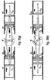
- Figure 2 schematically illustrates the operation of the engine of the present invention over one complete crankshaft rotation.
- Figures 2 ( a ) through 2( h ) illustrate the piston positions, intake and exhaust ports, and relative piston velocities at approximately 45° increments; note that crankshaft rotation in Figure 2 is counterclockwise.
- Crankshaft angle ⁇ (phi) is indicated by the small triangle and dashed arrowed arc. Since the connecting rods (pushrods and pullrods) cross at various crankshaft, positions, the four crankshaft journals are numbered for clarity, with journals 1, 2, 3, 4 connecting to the left outer, left inner, right inner, and right outer pistons, respectively.
- the end portions of the sliders of the inner pushrods and the convex surfaces at the rear of the inner pistons are shown, and the "effective" lengths of the inner pushrods are shown in dashed lines.
- Figure 2 ( a ) shows the engine at a crankshaft position of 0° (arbitrarily defined as "Top Dead Center,” or TDC, of the left cylinder).
- TDC Top Dead Center
- the left outer piston ( P LO ) and left inner piston ( P LI ) are very near their point of closest approach.
- a fuel charge would be injected into the left cylinder and combustion would begin (an actual engine would have more complex piston faces, forming a combustion chamber between them; the flat piston faces of Figure 2 are intended only to illustrate the relative piston locations).
- the intake and exhaust ports (IN and EX) of the left cylinder are completely closed by P LO and P LI , respectively.
- both pistons P LO and P LI have a slight motion to the right, as indicated by the arrows (the inner left piston, P LI , having just reversed direction). Since the crankshaft throws of the two pistons are different, the piston velocities will also be slightly different.
- pistons P LO and P LI of the left cylinder are moving apart in a power stroke, the outer piston having changed its direction of travel; the inner piston is moving at a significantly higher velocity than the outer piston, as indicated by the magnitude of the arrows.
- outer piston P RO has closed the exhaust ports EX, while intake ports IN remain partially open for supercharging.
- left inner piston P LI has opened the exhaust ports EX of the left cylinder, while the intake ports remain closed. In this "blowdown" condition, some of the kinetic energy of the expanding gases in the combustion chamber can be recovered externally for turbocharging (“pulse” turbocharging) or for generating electrical energy. In the right cylinder, the two cylinders continue the compression stroke.
- a single piston connected to a crankshaft journal through a connecting rod will generate free-mass forces of the first-order (having the same frequency as the crankshaft rotation) and of higher orders (at frequencies that are multiples of the crankshaft rotation frequency).
- the opposed-piston opposed-cylinder single central crankshaft configuration of the present invention allows for essentially total balancing of the free-mass forces, both of first-order and of higher order.
- the present invention utilizes a different approach, allowing some imbalance in each cylinder, which is offset by a corresponding imbalance in the opposite cylinder. This approach avoids some serious design constraints that would otherwise impact engine design.
- condition ( 1 ) and condition ( 2 ) are difficult, since, in any practical design, l 2 (the connecting rod length of the outer piston) will be significantly greater than l 1 (the connecting rod length of the inner piston). The more compact the engine, the greater this difference will be. This will be the case even with the slider pushrod of the preferred embodiment of the present invention, which effectively lengthens l 1 somewhat.
- the differing lengths of the two connecting rods imposes design constraints on the relative throws of the two pistons and on the relative effective masses of the pistons (if the dynamic forces within the cylinder are to be balanced).
- the throw of the outer piston, r 2 must be made greater than the throw of the inner piston, r 1 , in the same proportion as the connecting rod lengths.
- the effective mass of the inner piston, m 1 must be made greater than the effective mass of the outer piston, m 2 , again by the same proportion. Both of these requirements unduly constrain engine design. It may be desirable, for example, to increase the length of the outer piston, and hence also increase its mass, to accommodate a second set of piston rings as discussed below. It should also be noted that the effective mass of the outer piston includes a contribution from the pullrod which in a practical design will be greater than that of the pushrod's contribution to the inner piston's effective mass, thus tending to unbalance the cylinder further.
- the present invention does not seek to completely balance each cylinder, but instead utilizes the approach illustrated in Figures 3 ( b ), 3( c ), and 3( d ).
- the engine configuration of the present invention may be viewed as comprising the engines of Figures 3 ( b ) and 3( c ) superimposed, with the total free-mass forces equal to:
- ⁇ 1 and ⁇ 2 are selected such that the "engine” of Figure 3 ( b ) is 180° out of phase with the "engine” of Figure 3 ( c )
- sin( ⁇ 1 + ⁇ t) - sin( ⁇ 2 + ⁇ t)
- the total first-order free-mass forces for the "combined" engine will be proportional to m 1 ⁇ r 1 - m 2 ⁇ r 2 , and, if: m 1 ⁇ r 1
- each component "engine” one piston opens and closes exhaust ports and the other opens and closes intake ports, and may therefore preferably have different combustion face designs and different cross sections, the masses of the two pistons in each engine are matched.
- Balancing the engine in this manner has the significant advantage that the lengths of the connecting rods are not determinant factors in achieving dynamic balance.
- it is relatively straight-forward to determine by analysis the effective masses of the inner and outer pistons (including the contributions of the pullrods and pushrods), and then calculate the crankshaft throws, r 1 and r 2 , required to achieve balance.
- the greater effective masses of the outer pistons requires that the stroke of the outer pistons be significantly shorter than the throws of the inner pistons, which is the opposite of what would be required for balancing each cylinder independently.
- Asymmetric timing of the intake and exhaust ports in a two-cycle engine yields a number of important advantages. If the exhaust ports open before the intake ports, energy in the exhaust gases can be more effectively recovered by a turbocharger; if the exhaust ports close before the intake ports, the cylinder can be more effectively supercharged.
- the intake ports are controlled by one piston in each cylinder and the exhaust ports are controlled by the other piston, as described above.
- This configuration not only allows for effective scavenging ("uniflow" scavenging), but permits independent, asymmetric timing of the intake and exhaust ports.
- Asymmetric timing of the two pistons in each cylinder is achieved by changing the relative angular positions of the corresponding crankshaft journals (ref. Figure 1 ). Positioning the journals for the two pistons 180° apart would result in the two pistons both reaching their minimum and maximum excursions at the same time (symmetric timing); in the preferred embodiment of the present invention, the journals for the exhaust ports are angularly advanced by approximately 12.5°, and journals for the intake pistons are angularly retarded by approximately 12.5° ("Top Dead Center” thus still occurs at the same crankshaft angle as in the symmetrically timed engine, but the two pistons have a slight common motion with respect to the cylinder). As a result, the exhaust ports open before the intake ports for "blowdown" and close before the intake ports for supercharging.
- the engine configuration of the present invention thus incurs some imbalance of the free-mass forces (as discussed above) in exchange for asymmetric intake and exhaust port timing (a slight vertical offset of the two cylinders also contributes to this imbalance, as descussed below).
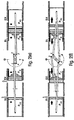
- This imbalance is kept to a minimum by reversing the relative positions of the intake and exhaust ports on one cylinder, as illustrated in Figure 4 .
- Figure 4 ( a ) shows an opposed-piston, opposed-cylinder configuration with symmetric piston timing.
- the exhaust ports of both cylinders are inboard (i.e., nearest the crankshaft) and the intake ports are outboard.
- the free-mass forces in this engine may be essentially totally balanced, as described above.
- Figure 4 ( b ) shows the same engine configuration with asymmetric exhaust and intake port timing.
- the two "engines” described in reference to Figures 3 ( b ) and 3( c ) are no longer out of phase, and thus this engine will have some residual, uncancelled first-order free-mass forces. This would be a viable engine configuration, though, as the uncancelled free-mass forces would be much less than those in a conventional inline four-cylinder engine.
- the present invention achieves a more optimal balance than that shown in Figure 4 ( b ) by reversing the intake and exhaust ports on one of the two cylinders, as illustrated in Figures 4 ( c ) and 4( d ).
- Figure 4 ( c ) shows a symmetrically timed engine with the exhaust and intake ports reversed on one cylinder; assuming the piston masses are the same, this engine has the same free-mass balance as the engine of 4( a )
- Figure 4 ( d ) shows the engine of the preferred embodiment. Reversing the positions of the exhaust and intake ports on one cylinder requires "splitting" the throws of the crankshaft to preserve correct port timing.
- This engine has unbalanced free mass forces, but these forces are negligible as they are less than 1/10 the free mass forces of second order seen in a 4- cylinder in-line engine.
- Improved balance results from each inner piston being substantially 180° out of phase with the outer piston in the opposite cylinder. If lambda (the crankshaft throw divided by the connecting rod length) of the inner pistons equals lambda of the outer piston, then again, this asymmetric configuration will be perfectly balanced (neglecting a minor additional imbalance introduced to further reduce friction losses, as discussed below). In the configuration of the preferred embodiment, therefore, the increased effective length of the inner piston pushrods contributes to the dynamic balance.
- Figure 5 shows the positions of the piston faces within the cylinders as a function of crankshaft angle for one complete crankshaft rotation.
- the positions of the intake and exhaust ports in the cylinder walls are also shown.
- the asymmetric timing of the two pistons within each cylinder can clearly be observed, with the two pistons reaching their maximum excursions at different crankshaft angles, and moving together with respect to the cylinder at "TDC".
- the inner pistons have a greater travel than the outer pistons, due to the different crankshaft throws. Since the intake ports are operated by the outer left and inner right pistons, and the exhaust ports are operated by the inner left and outer right pistons, the intake and exhaust port dimensions for the two cylinders will be somewhat different.
- balance depends on having four, six, eight, or more cylinders arranged such that the free mass forces contributed by the individual pistons cancel. Counter-rotating weights are also often employed, adding complexity to the engines.
- An advantage of the present invention is that substantially total balance may be achieved in a compact engine with only two cylinders. Larger engines may then be made by placing multiple small engines side-by-side, and coupling their crankshafts together. The coupling may be by such means as an electric clutch, allowing pairs of cylinders to be uncoupled when not needed at low loads. Engines currently exist which use less than all of their cylinders when run at partial load, but the cylinders remain connected to the crankshaft and the pistons continue to move within the cylinders, and therefore continue to be a friction load on the engine.
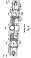
- Figures 6 , 7 , and 8 are front plan view, top plan view, and front sectional views, respectively.
- the Figures depict the engine at a crankshaft angle of 270° after TDC of the left cylinder.
- the engine comprises a left cylinder 1100, a right cylinder 1200, and a single central crankshaft 1300 located between the cylinders (the supporting structure of the engine is not shown).
- the left cylinder 1100 has an outer piston 1110 and an inner piston 1120, with combustion faces 1111 and 1121 respectively, the two pistons forming a combustion chamber 1150 between them.
- the right cylinder 1200 similarly has an outer piston 1210, an inner piston 1220, with combustion faces 1211 and 1221 and combustion chamber 1250.
- Each of the four pistons 1110, 1120, 1210, and 1220 are connected to a separate eccentric on the crankshaft 1300.
- the outer piston 1110 of the left cylinder is connected to the crankshaft by means of two pullrods 1411, one on either side of the cylinder; the outer piston 1210 of the right cylinder is similarly connected to the crankshaft by two pullrods 1421.
- the pullrods 1411 and 1421 communicate with the outer pistons by means of pins 1114 and 1214 that pass through slots 1115 and 1215 in the cylinder walls (see Figure 6 ).
- the inner piston 1120 of the left cylinder is connected to the crankshaft by means of pushrod 1412; the inner piston 1220 of the right cylinder is similarly connected to the crankshaft by pushrod 1422.
- the pushrods have concave ends 1413 and 1423 that ride on convex cylindrical surfaces 1125 and 1225 on the rear of the inner pistons.
- the four pistons 1110, 1120, 1210, and 1220 have a plurality of piston rings 1112, 1122, 1212, and 1222, respectively, located both behind the combustion faces and further along the piston bodies to prevent the escape of gases from the ports to the crankcase or through the slots in the cylinder walls through which the outer pistons communicate with the pullrods.
- the cylinders 1100 and 1200 each have intake, exhaust, and fuel injection ports.
- the intake and exhaust ports each comprise rows of ports surrounding the cylinders.
- the intake ports consist of two rows of ports (1161 a and 1161 b on the left cylinder and 1261 a and 1261 b on the right cylinder) which allows for improved scavenging, as described below.
- the outer piston 1110 opens and closes intake ports and the inner piston 1120 opens and closes exhaust ports 1163.
- Fuel injection port 1162 is located near the center of the cylinder.
- the inner piston 1220 opens and closes intake ports 1261 a and 1261 b and the outer piston opens and closes the exhaust ports. Again, fuel injection port 1262 is located near the center of the cylinder.
- the preferred implementation utilizes two superchargers (1510, 1520), one for each cylinder.
- the superchargers are electric motor/generator assisted turbochargers.
- the use of separate superchargers for the two cylinders makes pulse turbocharging practical, as described below.
- FIG 9 as viewed in conduction with Figure 8 illustrates the intake and exhaust port timing of the preferred embodiment of the invention.
- a crankshaft angle of 0° is arbitrarily defined as top-dead- center (TDC) on the left cylinder.
- TDC is here defined as the point at which the two pistons in the cylinder most closely approach one another; since the timing of one piston is advanced and the other is retarded, the two pistons will actually have a slight common velocity with respect to the cylinder at this point (towards the right in the illustration for both cylinders).
- the inboard piston in each cylinder is not attached to the corresponding connecting rod with a pin, but impinges on the concave cylindrical surface of the end of the rod through a crosshead slipper, giving the effect of a longer connecting rod (e.g., reduced lateral forces on the piston and therefore reduced friction).
- Timing for the left cylinder is illustrated in Figure 9 ( a ), and for the right cylinder in Figure 9 ( b ). Beginning at the position illustrated in Figure 8 and proceeding through a complete cycle for the left cylinder, the timing events are as follows:
- the power stroke extends beyond a crankshaft angle of 90°, with the gas between the inboard and outboard pistons expanding.
- the inboard piston 1120 begins to uncover exhaust ports 1163.
- the kinetic energy of the expanding gases may be utilized during the period designated [B] (for "blowdown") for pulse turbocharging, as discussed below.
- the outboard piston 1110 begins to uncover the first row of intake or scavenging ports, 1161a.
- This first row of ports is arranged so that the air enters somewhat tangent to the cylinder, creating swirl within the cylinder to scavenge the bulk of the exhaust gases within the cylinder through the exhaust ports.
- Both these ports and the 1161 b ports are angled towards the outboard end of the cylinder (in the preferred embodiment, approximately 23° ) such that intake air is directed tangential to the torroidal squish band of the outboard piston. Scavenging is designated [S] in Figure 9 ( a ).
- the second row of intake or scavenging ports 1161 b are uncovered. This row of ports is arranged such that the air is directed towards the center of the of the cylinder, rather than tangential around the edge of the cylinder.
- the incoming air entering through ports 1161 b passes over the face of the outboard piston 1110 and is directed by the central peak of the piston through the center of the combustion chamber. This serves to scavenge the central vortex of exhaust gases created by the swirl of the first row of scavenging ports.
- BDC bottom-dead-center
- the inboard piston 1120 covers the exhaust ports 1163. From event EX CLOSE until the outboard piston covers the first row of intake ports at IN A CLOSE, the cylinder may be charged with air under pressure using a turbocharger or supercharger, as described below. The period of charging is designated [C] in Figure 9 ( a ). Having the exhaust ports close before the intake ports provides the opportunity not only to supercharge the engine, but also in appropriate situations to restrict the amount of air entering the chamber. In low engine-load situations, for example, reducing the amount of air entering the chamber while correspondingly reducing the amount of fuel injected could improve mileage and reduce emissions. A turbocharger having an integral motor/generator would be suitable for this purpose, as described below.
- Figure 10 further illustrates the crankshaft of the presently preferred implementation.
- Each of the four crankshaft eccentrics 1311, 1312, 1321, and 1322 are uniquely positioned with respect to the crankshaft rotational axis 1310.
- the eccentrics for the inner pistons (1312, 1322) are further from the crankshaft rotational axis than the eccentrics for the outer pistons (1311, 1321), resulting in greater travel for the inner pistons than for the outer pistons.
- the eccentrics for the inner left piston (1312) and the outer right piston (1321), the pistons which open and close the exhaust ports in the two cylinders, are angularly advanced, while the eccentrics for the outer left piston (1311) and inner right piston (1322) are angularly retarded, as shown in sectional views B--B, C--C, D--D and E--E.
- Figure 11 shows the actual geometries of the crankshaft journals of the preferred implementation.
- the journals for the inner pistons have throws of 36.25 mm and the journals for the outer pistons have throws of 27.25 mm.
- the journals for the pistons controlling the exhaust ports of the left and right cylinders are advanced 7.5° and 13.7° respectively (again, crankshaft rotation is counterclockwise); the journals for the pistons controlling the intake ports for the left and right cylinders are retarded 17.5° and 11.3°, respectively.
- the differences in the angles for the left and right cylinders are the consequence of the engine asymmetries, including the 10 mm vertical offset of the two pistons, as described above.
- crankshaft The primary role of the crankshaft is to convert the reciprocating motion of the pistons, as conveyed through the pullrods and pushrods, into rotational motion. Unbalanced forces acting on a crankshaft result in increased friction between the crankshaft and its supporting bearings. The existence of unbalanced forces also complicates engine design, since the forces must somehow be mechanically transferred to the supporting structure of the engine, which must be sufficiently sturdy to accommodate the forces. In a standard four cylinder in-line engine, for example, the forces from all four pistons act in the same direction against the crankshaft, and literally tons of pressure must be transferred through the crankshaft main bearings to the engine structure. A typical four cylinder in-line engine will have five main bearings supporting the crankshaft.
- the engine configuration of the present invention allows for a simpler crankshaft design, since the reactive forces of the inner and outer pistons in each cylinder substantially cancel.
- the left cylinder as illustrated in Figure 4 ( d ) it can be seen that since the compression and combustion forces acting on the two pistons will be substantially equal and opposite, the pullrod of the outer piston will pull against the crankshaft with substantially the same force with which the pushrod of the inner piston pushes. The result will be a turning moment on the crankshaft, with only very minor uncancelled side-to-side and up-and-down forces (due to the slightly different angles of the pullrods and pushrods, and the asymmetrical timing of the two pistons).
- the loads on the crankshaft main bearings are therefore very small, which eliminates the need for any center main bearings and results in much lower friction losses than in an in-line four cylinder engine of comparable performance.
- FIG. 12 The method of supercharging the preferred embodiment is depicted in Figure 12 , with Figure 12 ( a ) illustrating prior art turbocharging, and Figure 12 ( b ) illustrating the electric motor/generator assisted turbocharging of the preferred embodiment.
- the engine configuration of the present invention with only two cylinders that are widely separated, together with independent intake and exhaust port timing, provides important opportunities for controlling the scavenging and intake air, and for recovering energy from the exhaust gases. In particular, with only two cylinders it becomes economically viable to provide a separate turbocharger for each cylinder, allowing for pulse turbocharging. Further, if the turbochargers incorporate electrical motor/generators, important performance advantages can be realized.
- the success or failure of the 2 -stroke design is determined primarily by its ability to scavenge.
- Optimal scavenging is needed over the entire engine map to achieve a perfect combustion, especially for controlling the EGR rate as required for NO x reduction.
- a positive boosting system such as turbocharging, may be necessary to ensure efficient operation at all load conditions.
- a belt-driven supercharger may be used in lieu of or in addition to the turbocharger to meet the combustion requirements.
- a supercharger may not be able to provide sufficient combustion pressure at starting.
- a conventional prior art turbocharger may be sufficient.
- the exhaust energy may not provide the required positive boosting to support compression.
- an electric assist turbocharger may be advantageous.
- An electric assist turbocharger like a conventional turbocharger, has an intake impellor that compresses intake gases, such as ambient air. This compressed air is presented to the intake ports of the cylinder.
- an exhaust impellor is coupled to the intake impellor. This coupling allows exhaust gases to motivate the intake impellor.
- an electric assist turbocharger also has an electric motor, which can motivate the intake impellor independent of the exhaust impellor and independent from the engine operating speed.
- Scavenge is dependent on the optimal pressure ratio between charge pressure and exhaust gas back pressure.
- the pressure ratio must primarily be adapted to engine rpm and must increase with increasing rpm.
- the pressure ratio also must be adaptable to load and transient operating conditions.
- an electrically assisted turbocharger with a permanent magnet brushless DC motor, enabling the usage of electronic control of turbo rpm and therefore of the boost pressure.
- the motor may be an induction, a switched reluctance, or some other type that will produce adequate power to perform the needed functions.
- This electrical unit may be used to assist the compressor when exhaust energy is not sufficient to provided needed compression of intake gases.
- the electrical assist turbo makes it possible to dynamically control the engine boost pressure.
- the size and weight of an electric assist turbocharger can be much smaller than a conventional mechanically driven supercharger.
- the electrical assist turbocharger of the present invention solves this problem by using an electrical motor to drive a compressor before engine start.
- cold air could be compressed to about 3.5 psi.
- ambient air of about -20 degrees centigrade may be presented to the combustion chamber at about 80 degrees C. This heating of the air is a result of the compression process.
- An electric motor causes the compression impellor of a turbocharger to spin, forcing compressed air into the cylinder, the air naturally heats.
- the electric assist turbo can heat intake air prior to ignition sequence.
- ignition sequence may be delayed by controlling the timing of the release of fuel.
- the reciprocating internal combustion engine is inherently an unsteady pulsating flow device. Turbines can be designed to accept such an unsteady flow, but they operate more efficiently under steady flow conditions.
- two approaches for recovering a fraction of the available exhaust energy are commonly used: constant-pressure turbocharging and pulse turbocharging.
- constant-pressure turbocharging an exhaust manifold of sufficiently large volume to damp out the mass flow and pressure pulses is used so that the flow to the turbine is essentially steady.
- the disadvantage of this approach is that it does not make full use of the high kinetic energy of the gases leaving the exhaust port; the losses inherent in the mixing of this high- velocity gas with a large volume of low-velocity gas cannot be recovered.
- pulse turbocharging short small-cross-section pipes connect each exhaust port to the turbine so that much of the kinetic energy associated with the exhaust blowdown can be utilized.
- the turbine must be specifically designed for this pulsating flow to achieve adequate efficiencies.
- constant-pressure turbocharging is used.
- turbocharged heavy-duty engines employ a divided exhaust manifold system connected to a divided volute turbine casing.
- six-cylinder engines usually employ an exhaust manifold consisting of two branches; one branch covering the exhaust ports of cylinders 1, 2 and 3, and the other covering cylinders 4, 5 and 6.
- the exhaust gas flow path remains divided from the manifold branch, through the divided casing turbine volute, up to the peripheral entrance to the turbine wheel.
- the divided manifold system prevents the blow-down pulse of each cylinder from interfering with the gas removal process from the cylinder that has fired previously.
- the turbocharger turbine casings are designed with a converging nozzle section in order to re-create the high velocity necessary to drive the turbine wheel. Since the exhaust gas must flow through a relatively small flow area at the throat of the nozzle section, a high back pressure is created in the manifold branch that increases engine pumping losses.
- the engine of the present invention engine offers the possibility of utilizing the velocity generated by the cylinder blow-down process to drive the turbine directly. Since the exhaust gas will enter the turbine casing immediately after leaving the cylinder collection chamber, there will be no need to employ a nozzle section in the turbine casing. Additionally, since there will be one turbocharger per cylinder, the turbine casing will not need an internal division, thereby allowing full undivided admission of the exhaust gas to the turbine wheel periphery and maximizing turbine efficiency.
- blow-down exhaust gas velocity from cylinder to turbine wheel can be accomplished due to the unique design of the engine of the present invention and the utilization of one turbocharger per cylinder.
- the absence of a nozzle section in the turbine casing will result in a very low back pressure in the exhaust system when the pistons are exhausting the cylinder.
- the differential pressure across the cylinder will be much greater with the engine of the present invention. This will result in a significant improvement in fuel consumption when compared with standard turbocharged two or four-cycle engines.
- the inner piston connecting rod on the engine of the present invention is subject only to compression loads that eliminates a need for a wrist pin. This is replaced by a concave radius of large diameter on which a sliding crosshead slipper impinges, and on which the connecting rod slides ( Figure 13 ).
- the forces at the end of the crosshead slipper must be greater than zero. This is the case as long as the coefficient of friction between the crosshead slipper and the slide of the connecting rod is lower than 0.45.
- the theoretical rod length is increased by over 100 millimeters, thereby decreasing the lateral forces acting on the piston and the friction losses in the engine.
- ⁇ for the inboard piston is decreased, the free mass forces described above are also minimized.
- the outer pistons transfer their reciprocating motion to the crankshaft via two connecting rods outside the cylinder ( Figure 14 ).
- These connecting rods are subject only to tension loads, and are therefore called pull rods.
- the pull rods are kept light by taking advantage of a constant tension no buckling load condition and designing them long and thin.
- the goals for the combustion system are:
- the cyclic combustion process is superior to the continuous combustion process (gas turbine, Sterling engine, etc.) in an internal combustion engine because the working gas temperature can be much higher than the wall temperature. This leads to a much higher thermodynamic efficiency.
- the DI Diesel has the highest potential because it offers the opportunity for an optimal heat release by controlling the injection rate over crank angle. Creating the desired combustion process (which delivers the optimal heat release) requires the combination of the correct injection rate and swirl characteristic.
- Figure 15 depicts the combustion chamber just prior to top dead center ( Figure 15 ( a )), at top dead center ( Figure 15 ( b )), and just after top dead center ( Figure 15 ( c )).
- the combustion chamber is formed by the exhaust piston which has a torroidal shape matching the intake piston with a reverse profile.
- the pistons form a broad area squish band that creates a swirl of high intensity near top dead center.
- This conventional combustion system offered by the opposed piston design has the potential to improve the exhaust emissions, and also fuel consumption, power output and comfort.
- the engine of the present invention provides the opportunity for unconventional new combustion systems, as shown in Figures 16 ( a ) and 16( b ).
- a NO x reducing heat sink or a catalytic converter between the combustion chamber and the cylinder (ref. Figure 16 ( a )).
- the converter will be attached to the exhaust piston; fuel is injected by spraying directly into the combustion chamber.
- Such a combustion system might offer a breakthrough in extreme low emission combustion without sacrificing the fuel consumption, power output or comfort.
- Figure 16 ( b ) represents a combustion chamber design having a spherical shape located very near the fuel injector which preserves the high pressure of the injected fuel and avoids the necessity of a narrow channel and the problems associated with a narrow channel.
Landscapes
- Engineering & Computer Science (AREA)
- General Engineering & Computer Science (AREA)
- Mechanical Engineering (AREA)
- Chemical & Material Sciences (AREA)
- Combustion & Propulsion (AREA)
- Physics & Mathematics (AREA)
- Acoustics & Sound (AREA)
- Aviation & Aerospace Engineering (AREA)
- Shafts, Cranks, Connecting Bars, And Related Bearings (AREA)
- Supercharger (AREA)
- Cylinder Crankcases Of Internal Combustion Engines (AREA)
Claims (11)
- Un moteur à combustion interne comprenant :des premier et deuxième cylindres opposés, chaque cylindre ayant des pistons interne et externe opposés, des orifices d'admission d'air (IN) et des orifices d'échappement (EX) ; les pistons dans chaque cylindre fonctionnent afin d'ouvrir ses orifices d'échappement (EX) avant ses orifices d'admission d'air (IN) et de fermer les orifices d'échappement (EX) avant que ses orifices d'admission d'air (IN) se ferment ;caractérisé en ce que le premier cylindre a un orifice d'admission d'air (IN) positionné adjacent à un vilebrequin, et un orifice d'échappement (EX) à distance du vilebrequin, tandis que le deuxième cylindre a un orifice d'admission d'air (IN) positionné à distance du vilebrequin, et un orifice d'échappement (EX) adjacent au vilebrequin, le vilebrequin ayant des tourillons, des tiges de culbuteur et des tiges de rappel arrangés de façon asymétrique pour entraîner de façon asymétrique les tourillons des pistons de telle sorte qu'une synchronisation asymétrique de l'ouverture et de la fermeture des orifices d'admission (IN) et des orifices d'échappement (EX) soit fournie sur chaque cylindre et qu'un déséquilibre dynamique entre les premier et deuxième cylindres soit minimisé.
- Un moteur à combustion interne tel que dans la revendication 1, lequel inclut de plus un turbocompresseur (510 ; 520) relié à au moins un cylindre et la vélocité générée par la chasse du cylindre entraîne la turbine de turbocompresseur directement.
- Le moteur de la revendication 2 dans lequel le turbocompresseur (510, 520) comprend de plus un moteur d'assistance électrique de sorte que des gaz comprimés fournis aux orifices d'admission (IN) puissent être opérés indépendamment de gaz de chasse provenant des orifices d'échappement (EX) et indépendamment de la vitesse de fonctionnement du moteur.
- Un moteur à combustion interne tel que dans la revendication 2 ou 3, dans lequel les cylindres ont des axes longitudinaux parallèles et lesdits axes sont déportés dans des directions opposées par rapport à l'axe du vilebrequin.
- Un moteur à combustion interne tel que dans n'importe lesquelles des revendications 2 à 4, dans lequel le turbocompresseur (510, 520) est couplé à des orifices d'échappement (EX) d'un cylindre associé afin de recevoir des gaz de chasse provenant de celui-ci et à des orifices d'admission (IN) du cylindre associé afin d'appliquer de l'air pressurisé sur ceux-ci.
- Le moteur de la revendication 5 dans lequel le turbocompresseur (510, 520) comprend un moteur d'assistance électrique couplé à un rouet d'admission de sorte que le rouet d'admission puisse appliquer de l'air pressurisé sur l'orifice d'admission indépendamment des gaz de chasse.
- Un moteur à combustion interne tel que dans n'importe lesquelles des revendications 2 à 6, dans lequel chaque piston interne a sur son extrémité à distance de la chambre de combustion une face d'extrémité lisse qui est courbée de façon convexe dans un plan perpendiculaire à l'axe longitudinal du vilebrequin, et dans lequel une commande par tige et culbuteur associée inclut une bielle couplée à un tourillon sur le vilebrequin et présentant une surface d'extrémité externe de forme concave qui se met en prise par coulissement avec la face d'extrémité courbée du piston interne ; la longueur effective (I1, I2) de chaque tige de culbuteur incluant alors le rayon de la face d'extrémité courbée de façon convexe du piston interne associé.
- Un moteur à combustion interne tel que dans n'importe lesquelles des revendications 2 à 7, dans lequel chaque piston interne a sur son extrémité à distance de la chambre de combustion une face d'extrémité lisse qui est courbée de façon convexe dans un plan perpendiculaire à l'axe longitudinal du vilebrequin, et dans lequel une commande par tige et culbuteur associée inclut une bielle couplée à un tourillon sur le vilebrequin et présentant une surface d'extrémité externe de forme concave qui se met en prise par coulissement avec la face d'extrémité courbée du piston interne.
- Un moteur à combustion interne tel que dans la revendication 5, dans lequel cet au moins un turbocompresseur (510, 520) est couplé à un cylindre de manière à fournir une pressurisation maximum peu avant que les orifices d'admission (IN) se ferment.
- Un moteur à combustion interne tel que dans n'importe lesquelles des revendications 2 à 9, dans lequel le moteur est configuré de sorte que du gaz d'échappement puisse être converti via un turbocompresseur (510, 520) en énergie électrique en stock, le turbocompresseur étant couplé de façon électrique au stock et configuré pour utiliser l'énergie stockée afin de motiver le turbocompresseur.
- Un moteur à combustion interne tel que dans la revendication 4, dans lequel les tourillons arrangés de façon asymétrique guident, durant toute la course de détente, le piston externe vers l'extérieur et le piston interne vers l'intérieur.
Priority Applications (3)
| Application Number | Priority Date | Filing Date | Title |
|---|---|---|---|
| EP08156757A EP1980731B1 (fr) | 2000-12-15 | 2000-12-15 | Moteur à combustion interne ayant un vilebrequin unique et des cylindres opposés à pistons opposés |
| AT08156757T ATE535693T1 (de) | 2000-12-15 | 2000-12-15 | Verbrennungsmotor mit einer einzigen kurbelwelle und entgegengesetzten zylindern mit entgegengesetzten kolben |
| EP10012884A EP2320048A1 (fr) | 2000-12-15 | 2000-12-15 | Moteur à combustion interne ayant un vilebrequin unique et des cylindres opposés à pistons opposés |
Applications Claiming Priority (1)
| Application Number | Priority Date | Filing Date | Title |
|---|---|---|---|
| PCT/US2000/034122 WO2002048524A1 (fr) | 2000-12-15 | 2000-12-15 | Moteur a combustion interne dote d'un vilebrequin unique et possedant des cylindres opposes pourvus de pistons opposes |
Related Child Applications (1)
| Application Number | Title | Priority Date | Filing Date |
|---|---|---|---|
| EP08156757A Division EP1980731B1 (fr) | 2000-12-15 | 2000-12-15 | Moteur à combustion interne ayant un vilebrequin unique et des cylindres opposés à pistons opposés |
Publications (2)
| Publication Number | Publication Date |
|---|---|
| EP1341999A1 EP1341999A1 (fr) | 2003-09-10 |
| EP1341999B1 true EP1341999B1 (fr) | 2008-12-03 |
Family
ID=21742071
Family Applications (3)
| Application Number | Title | Priority Date | Filing Date |
|---|---|---|---|
| EP10012884A Withdrawn EP2320048A1 (fr) | 2000-12-15 | 2000-12-15 | Moteur à combustion interne ayant un vilebrequin unique et des cylindres opposés à pistons opposés |
| EP00984454A Expired - Lifetime EP1341999B1 (fr) | 2000-12-15 | 2000-12-15 | Moteur a combustion interne dote d'un vilebrequin unique et possedant des cylindres opposes pourvus de pistons opposes |
| EP08156757A Expired - Lifetime EP1980731B1 (fr) | 2000-12-15 | 2000-12-15 | Moteur à combustion interne ayant un vilebrequin unique et des cylindres opposés à pistons opposés |
Family Applications Before (1)
| Application Number | Title | Priority Date | Filing Date |
|---|---|---|---|
| EP10012884A Withdrawn EP2320048A1 (fr) | 2000-12-15 | 2000-12-15 | Moteur à combustion interne ayant un vilebrequin unique et des cylindres opposés à pistons opposés |
Family Applications After (1)
| Application Number | Title | Priority Date | Filing Date |
|---|---|---|---|
| EP08156757A Expired - Lifetime EP1980731B1 (fr) | 2000-12-15 | 2000-12-15 | Moteur à combustion interne ayant un vilebrequin unique et des cylindres opposés à pistons opposés |
Country Status (6)
| Country | Link |
|---|---|
| EP (3) | EP2320048A1 (fr) |
| JP (1) | JP3859595B2 (fr) |
| AT (2) | ATE416303T1 (fr) |
| AU (1) | AU2001221068A1 (fr) |
| DE (1) | DE60041008D1 (fr) |
| WO (1) | WO2002048524A1 (fr) |
Cited By (1)
| Publication number | Priority date | Publication date | Assignee | Title |
|---|---|---|---|---|
| WO2013063607A1 (fr) * | 2011-10-27 | 2013-05-02 | Mil-Spec Magnetics, Inc. | Moteur à déplacement multiple |
Families Citing this family (19)
| Publication number | Priority date | Publication date | Assignee | Title |
|---|---|---|---|---|
| WO2003078835A1 (fr) | 2002-03-15 | 2003-09-25 | Advanced Propulsion Technologies, Inc. | Moteur a capacite de pompage |
| EP1639243B1 (fr) | 2003-06-25 | 2016-04-27 | Peter Hofbauer | Moteur a combustion interne |
| FR2888907A1 (fr) * | 2005-07-21 | 2007-01-26 | Marie Therese Mazille | Dispositif pour ouvrir et fermer les lumieres de distribution dans les moteurs deux temps, et guider les pistons quand ils sont monocylindriques. |
| FR2907283B1 (fr) * | 2006-10-17 | 2013-04-19 | Airbus France | Dispositif et procede d'alimentation electrique d'au moins une machine a induction a bord d'un aeronef |
| CN102947545B (zh) | 2010-04-27 | 2015-11-25 | 阿凯提兹动力公司 | 用于对置活塞发动机的燃烧室构造 |
| US9512779B2 (en) | 2010-04-27 | 2016-12-06 | Achates Power, Inc. | Swirl-conserving combustion chamber construction for opposed-piston engines |
| US10180115B2 (en) | 2010-04-27 | 2019-01-15 | Achates Power, Inc. | Piston crown bowls defining combustion chamber constructions in opposed-piston engines |
| EP2998541B1 (fr) | 2010-08-16 | 2017-01-04 | Achates Power, Inc. | Motifs de pulvérisation d'injection de carburant pour moteurs à pistons opposés |
| US8746204B2 (en) * | 2010-09-29 | 2014-06-10 | Ecomotors, Inc. | Frictionless rocking joint |
| US9309807B2 (en) | 2011-05-18 | 2016-04-12 | Achates Power, Inc. | Combustion chamber constructions for opposed-piston engines |
| GB2493061A (en) * | 2011-07-15 | 2013-01-23 | Ecomotors Internat Inc | Opposed piston engine with toroidal combustion chamber |
| GB2496479A (en) | 2011-11-11 | 2013-05-15 | Ecomotors Internat Inc | Intake System for an Opposed-Piston Engine |
| BR112015000026A2 (pt) * | 2012-07-02 | 2017-06-27 | Pinnacle Engines Inc | motor a diesel de relação de compressão variável |
| CN103322019A (zh) * | 2013-06-09 | 2013-09-25 | 安徽中鼎动力有限公司 | 一种对置活塞对置气缸自由式活塞发动机曲轴 |
| US9211797B2 (en) | 2013-11-07 | 2015-12-15 | Achates Power, Inc. | Combustion chamber construction with dual mixing regions for opposed-piston engines |
| US9995213B2 (en) | 2015-03-31 | 2018-06-12 | Achates Power, Inc. | Asymmetrically-shaped combustion chamber for opposed-piston engines |
| US9840965B2 (en) | 2015-07-31 | 2017-12-12 | Achates Power, Inc. | Skewed combustion chamber for opposed-piston engines |
| CN110462193B (zh) * | 2017-03-22 | 2022-04-12 | 阿凯提兹动力公司 | 用于对置活塞发动机的汽缸孔表面结构 |
| WO2023079397A1 (fr) * | 2021-11-05 | 2023-05-11 | Aquarius Engines (A.M) Ltd. | Générateur de puissance électromagnétique oscillant |
Family Cites Families (20)
| Publication number | Priority date | Publication date | Assignee | Title |
|---|---|---|---|---|
| DE114341C (fr) * | ||||
| US1332756A (en) * | 1918-05-09 | 1920-03-02 | Lemma J Root | Rotary internal-combustion engine |
| GB184838A (en) * | 1921-04-18 | 1922-08-18 | John Douglas | Improvements in two-stroke internal combustion engines |
| US2093433A (en) * | 1933-06-09 | 1937-09-21 | Greene Catharine De Motte | Internal combustion engine |
| US1997396A (en) * | 1934-04-18 | 1935-04-09 | Michell Crankless Engines Corp | Crankless mechanism |
| FR852918A (fr) * | 1938-04-12 | 1940-03-06 | Maschf Augsburg Nuernberg Ag | Moteur à gaz polycylindrique à grande puissance et à grande vitesse |
| GB531009A (en) | 1939-07-08 | 1940-12-27 | Edward Moller | Improvements in two-stroke cycle internal combustion engines |
| GB565150A (en) * | 1943-03-24 | 1944-10-30 | John Alfred Emerson Reynolds | Improvements in or relating to internal-combustion engines |
| GB805640A (en) * | 1955-03-23 | 1958-12-10 | Nordberg Manufacturing Co | Improvements in or relating to two-stroke internal combustion engines |
| US4419969A (en) * | 1979-07-31 | 1983-12-13 | Bundrick Jr Benjamin | Flexible cylinder-head internal combustion engine with cylinder compression adjustable for use with available fluid fuels |
| GB8404159D0 (en) * | 1984-02-17 | 1984-03-21 | Sophocles Papanicolacu J P | Ic engine |
| SG26385G (en) * | 1986-09-04 | 1995-09-01 | Galbraith Eng Pty Ltd | Reciprocatory machines |
| US5058536A (en) * | 1987-01-28 | 1991-10-22 | Johnston Richard P | Variable-cycle reciprocating internal combustion engine |
| US4869212A (en) * | 1987-09-23 | 1989-09-26 | Automated Marine Propulsions Systems, Inc. | Modular universal combusion engine |
| US5058537A (en) * | 1989-04-21 | 1991-10-22 | Paul Marius A | Optimized high pressure internal combustion engines |
| JP3074861B2 (ja) * | 1991-10-22 | 2000-08-07 | いすゞ自動車株式会社 | 2サイクルエンジン |
| DE4243255A1 (de) * | 1992-12-19 | 1994-06-23 | Graf Peter Von Ingelheim | Verbrennungsmotor mit zwei Kolben pro Arbeitsraum, insbesondere Zweitaktmotor mit Gleichstromspülung |
| DE19503444C1 (de) * | 1995-02-03 | 1996-05-15 | Daimler Benz Ag | Zweitakt-Gegenkolbenmotor |
| US5560208A (en) * | 1995-07-28 | 1996-10-01 | Halimi; Edward M. | Motor-assisted variable geometry turbocharging system |
| US5906098A (en) * | 1996-07-16 | 1999-05-25 | Turbodyne Systems, Inc. | Motor-generator assisted turbocharging systems for use with internal combustion engines and control method therefor |
-
2000
- 2000-12-15 EP EP10012884A patent/EP2320048A1/fr not_active Withdrawn
- 2000-12-15 EP EP00984454A patent/EP1341999B1/fr not_active Expired - Lifetime
- 2000-12-15 AT AT00984454T patent/ATE416303T1/de not_active IP Right Cessation
- 2000-12-15 EP EP08156757A patent/EP1980731B1/fr not_active Expired - Lifetime
- 2000-12-15 JP JP2002550220A patent/JP3859595B2/ja not_active Expired - Fee Related
- 2000-12-15 AU AU2001221068A patent/AU2001221068A1/en not_active Abandoned
- 2000-12-15 AT AT08156757T patent/ATE535693T1/de active
- 2000-12-15 WO PCT/US2000/034122 patent/WO2002048524A1/fr active Application Filing
- 2000-12-15 DE DE60041008T patent/DE60041008D1/de not_active Expired - Lifetime
Cited By (2)
| Publication number | Priority date | Publication date | Assignee | Title |
|---|---|---|---|---|
| WO2013063607A1 (fr) * | 2011-10-27 | 2013-05-02 | Mil-Spec Magnetics, Inc. | Moteur à déplacement multiple |
| US9080507B2 (en) | 2011-10-27 | 2015-07-14 | Anthony Rohan Gunewardena | Multi-displacement internal combustion engine that removably couples a plurality of engine modules, axially at their crankshafts, to a single common output |
Also Published As
| Publication number | Publication date |
|---|---|
| ATE535693T1 (de) | 2011-12-15 |
| EP1980731B1 (fr) | 2011-11-30 |
| DE60041008D1 (de) | 2009-01-15 |
| ATE416303T1 (de) | 2008-12-15 |
| AU2001221068A1 (en) | 2002-06-24 |
| JP3859595B2 (ja) | 2006-12-20 |
| EP1980731A2 (fr) | 2008-10-15 |
| EP2320048A1 (fr) | 2011-05-11 |
| EP1980731A3 (fr) | 2008-12-24 |
| EP1341999A1 (fr) | 2003-09-10 |
| WO2002048524A1 (fr) | 2002-06-20 |
| JP2005500450A (ja) | 2005-01-06 |
Similar Documents
| Publication | Publication Date | Title |
|---|---|---|
| US6170443B1 (en) | Internal combustion engine with a single crankshaft and having opposed cylinders with opposed pistons | |
| EP1341999B1 (fr) | Moteur a combustion interne dote d'un vilebrequin unique et possedant des cylindres opposes pourvus de pistons opposes | |
| US8499726B2 (en) | Internal combustion engines | |
| US5431130A (en) | Internal combustion engine with stroke specialized cylinders | |
| US20110239642A1 (en) | Double-Acting, Two-Stroke HCCI Compound Free-Piston Rotating-Shaft Engine | |
| US6662775B2 (en) | Integral air compressor for boost air in barrel engine | |
| Cantore et al. | A new design concept for 2-Stroke aircraft Diesel engines | |
| AU2013350310B2 (en) | Internal combustion engine with asymmetric port timing | |
| GB2410060A (en) | A two-stroke compression-ignition internal combustion engine | |
| AU638720B2 (en) | Reciprocating piston engine with pumping and power cylinders | |
| US6467440B1 (en) | Two stroke internal combustion engine | |
| CN103174513A (zh) | 一种具有对置活塞对置气缸单曲轴的内燃机 | |
| US4781154A (en) | Two-cycle internal combustion engine | |
| US3042012A (en) | Two-stroke internal combustion engines | |
| EP0057591B1 (fr) | Moteur à combustion interne | |
| GB2367328A (en) | I.c. engine with opposed pistons and cam surfaces to transmit the piston movements | |
| WO2002023025A1 (fr) | Moteur a combustion interne diesel | |
| JP3799658B2 (ja) | 4サイクルエンジンの過給装置 | |
| JPH05187234A (ja) | タ−ボ過給機付きエンジンの吸気装置 | |
| WO2012163310A1 (fr) | Moteur à combustion interne multicylindre utilisant les gaz d'échappement pour accroître le remplissage des cylindres |
Legal Events
| Date | Code | Title | Description |
|---|---|---|---|
| PUAI | Public reference made under article 153(3) epc to a published international application that has entered the european phase |
Free format text: ORIGINAL CODE: 0009012 |
|
| 17P | Request for examination filed |
Effective date: 20030610 |
|
| AK | Designated contracting states |
Kind code of ref document: A1 Designated state(s): AT BE CH CY DE DK ES FI FR GB GR IE IT LI LU MC NL PT SE TR |
|
| AX | Request for extension of the european patent |
Extension state: AL LT LV MK RO SI |
|
| RAP1 | Party data changed (applicant data changed or rights of an application transferred) |
Owner name: ADVANCED PROPULSION TECHNOLOGIES, INC. |
|
| 17Q | First examination report despatched |
Effective date: 20060803 |
|
| 17Q | First examination report despatched |
Effective date: 20060803 |
|
| GRAP | Despatch of communication of intention to grant a patent |
Free format text: ORIGINAL CODE: EPIDOSNIGR1 |
|
| GRAS | Grant fee paid |
Free format text: ORIGINAL CODE: EPIDOSNIGR3 |
|
| GRAA | (expected) grant |
Free format text: ORIGINAL CODE: 0009210 |
|
| AK | Designated contracting states |
Kind code of ref document: B1 Designated state(s): AT BE CH CY DE DK ES FI FR GB GR IE IT LI LU MC NL PT SE TR |
|
| REG | Reference to a national code |
Ref country code: GB Ref legal event code: FG4D |
|
| RAP2 | Party data changed (patent owner data changed or rights of a patent transferred) |
Owner name: ADVANCED PROPULSION TECHNOLOGIES, INC. |
|
| REG | Reference to a national code |
Ref country code: CH Ref legal event code: EP |
|
| REG | Reference to a national code |
Ref country code: IE Ref legal event code: FG4D |
|
| REF | Corresponds to: |
Ref document number: 60041008 Country of ref document: DE Date of ref document: 20090115 Kind code of ref document: P |
|
| REG | Reference to a national code |
Ref country code: SE Ref legal event code: TRGR |
|
| PG25 | Lapsed in a contracting state [announced via postgrant information from national office to epo] |
Ref country code: ES Free format text: LAPSE BECAUSE OF FAILURE TO SUBMIT A TRANSLATION OF THE DESCRIPTION OR TO PAY THE FEE WITHIN THE PRESCRIBED TIME-LIMIT Effective date: 20090314 |
|
| NLV1 | Nl: lapsed or annulled due to failure to fulfill the requirements of art. 29p and 29m of the patents act | ||
| PG25 | Lapsed in a contracting state [announced via postgrant information from national office to epo] |
Ref country code: NL Free format text: LAPSE BECAUSE OF FAILURE TO SUBMIT A TRANSLATION OF THE DESCRIPTION OR TO PAY THE FEE WITHIN THE PRESCRIBED TIME-LIMIT Effective date: 20081203 Ref country code: FI Free format text: LAPSE BECAUSE OF FAILURE TO SUBMIT A TRANSLATION OF THE DESCRIPTION OR TO PAY THE FEE WITHIN THE PRESCRIBED TIME-LIMIT Effective date: 20081203 |
|
| PG25 | Lapsed in a contracting state [announced via postgrant information from national office to epo] |
Ref country code: MC Free format text: LAPSE BECAUSE OF NON-PAYMENT OF DUE FEES Effective date: 20081231 Ref country code: BE Free format text: LAPSE BECAUSE OF FAILURE TO SUBMIT A TRANSLATION OF THE DESCRIPTION OR TO PAY THE FEE WITHIN THE PRESCRIBED TIME-LIMIT Effective date: 20081203 |
|
| REG | Reference to a national code |
Ref country code: CH Ref legal event code: PL |
|
| PG25 | Lapsed in a contracting state [announced via postgrant information from national office to epo] |
Ref country code: PT Free format text: LAPSE BECAUSE OF FAILURE TO SUBMIT A TRANSLATION OF THE DESCRIPTION OR TO PAY THE FEE WITHIN THE PRESCRIBED TIME-LIMIT Effective date: 20090504 Ref country code: AT Free format text: LAPSE BECAUSE OF FAILURE TO SUBMIT A TRANSLATION OF THE DESCRIPTION OR TO PAY THE FEE WITHIN THE PRESCRIBED TIME-LIMIT Effective date: 20081203 |
|
| REG | Reference to a national code |
Ref country code: IE Ref legal event code: MM4A |
|
| PLBE | No opposition filed within time limit |
Free format text: ORIGINAL CODE: 0009261 |
|
| STAA | Information on the status of an ep patent application or granted ep patent |
Free format text: STATUS: NO OPPOSITION FILED WITHIN TIME LIMIT |
|
| PG25 | Lapsed in a contracting state [announced via postgrant information from national office to epo] |
Ref country code: CH Free format text: LAPSE BECAUSE OF NON-PAYMENT OF DUE FEES Effective date: 20081231 Ref country code: LI Free format text: LAPSE BECAUSE OF NON-PAYMENT OF DUE FEES Effective date: 20081231 Ref country code: IE Free format text: LAPSE BECAUSE OF NON-PAYMENT OF DUE FEES Effective date: 20081215 Ref country code: DK Free format text: LAPSE BECAUSE OF FAILURE TO SUBMIT A TRANSLATION OF THE DESCRIPTION OR TO PAY THE FEE WITHIN THE PRESCRIBED TIME-LIMIT Effective date: 20081203 |
|
| 26N | No opposition filed |
Effective date: 20090904 |
|
| PG25 | Lapsed in a contracting state [announced via postgrant information from national office to epo] |
Ref country code: CY Free format text: LAPSE BECAUSE OF FAILURE TO SUBMIT A TRANSLATION OF THE DESCRIPTION OR TO PAY THE FEE WITHIN THE PRESCRIBED TIME-LIMIT Effective date: 20081203 Ref country code: LU Free format text: LAPSE BECAUSE OF NON-PAYMENT OF DUE FEES Effective date: 20081215 |
|
| PG25 | Lapsed in a contracting state [announced via postgrant information from national office to epo] |
Ref country code: TR Free format text: LAPSE BECAUSE OF FAILURE TO SUBMIT A TRANSLATION OF THE DESCRIPTION OR TO PAY THE FEE WITHIN THE PRESCRIBED TIME-LIMIT Effective date: 20081203 |
|
| PG25 | Lapsed in a contracting state [announced via postgrant information from national office to epo] |
Ref country code: GR Free format text: LAPSE BECAUSE OF FAILURE TO SUBMIT A TRANSLATION OF THE DESCRIPTION OR TO PAY THE FEE WITHIN THE PRESCRIBED TIME-LIMIT Effective date: 20090304 |
|
| PGFP | Annual fee paid to national office [announced via postgrant information from national office to epo] |
Ref country code: SE Payment date: 20101213 Year of fee payment: 11 |
|
| PGFP | Annual fee paid to national office [announced via postgrant information from national office to epo] |
Ref country code: IT Payment date: 20101218 Year of fee payment: 11 |
|
| REG | Reference to a national code |
Ref country code: SE Ref legal event code: EUG |
|
| PG25 | Lapsed in a contracting state [announced via postgrant information from national office to epo] |
Ref country code: SE Free format text: LAPSE BECAUSE OF NON-PAYMENT OF DUE FEES Effective date: 20111216 |
|
| PG25 | Lapsed in a contracting state [announced via postgrant information from national office to epo] |
Ref country code: IT Free format text: LAPSE BECAUSE OF NON-PAYMENT OF DUE FEES Effective date: 20111215 |
|
| REG | Reference to a national code |
Ref country code: FR Ref legal event code: PLFP Year of fee payment: 16 |
|
| REG | Reference to a national code |
Ref country code: FR Ref legal event code: PLFP Year of fee payment: 17 |
|
| PGFP | Annual fee paid to national office [announced via postgrant information from national office to epo] |
Ref country code: GB Payment date: 20161228 Year of fee payment: 17 |
|
| PGFP | Annual fee paid to national office [announced via postgrant information from national office to epo] |
Ref country code: FR Payment date: 20161227 Year of fee payment: 17 |
|
| PGFP | Annual fee paid to national office [announced via postgrant information from national office to epo] |
Ref country code: DE Payment date: 20161229 Year of fee payment: 17 |
|
| REG | Reference to a national code |
Ref country code: DE Ref legal event code: R119 Ref document number: 60041008 Country of ref document: DE |
|
| GBPC | Gb: european patent ceased through non-payment of renewal fee |
Effective date: 20171215 |
|
| REG | Reference to a national code |
Ref country code: FR Ref legal event code: ST Effective date: 20180831 |
|
| PG25 | Lapsed in a contracting state [announced via postgrant information from national office to epo] |
Ref country code: DE Free format text: LAPSE BECAUSE OF NON-PAYMENT OF DUE FEES Effective date: 20180703 Ref country code: FR Free format text: LAPSE BECAUSE OF NON-PAYMENT OF DUE FEES Effective date: 20180102 |
|
| PG25 | Lapsed in a contracting state [announced via postgrant information from national office to epo] |
Ref country code: GB Free format text: LAPSE BECAUSE OF NON-PAYMENT OF DUE FEES Effective date: 20171215 |