EP1340660A2 - Brake and accelerator pedals for golf and utility vehicles made of molded plastic - Google Patents
Brake and accelerator pedals for golf and utility vehicles made of molded plastic Download PDFInfo
- Publication number
- EP1340660A2 EP1340660A2 EP03004491A EP03004491A EP1340660A2 EP 1340660 A2 EP1340660 A2 EP 1340660A2 EP 03004491 A EP03004491 A EP 03004491A EP 03004491 A EP03004491 A EP 03004491A EP 1340660 A2 EP1340660 A2 EP 1340660A2
- Authority
- EP
- European Patent Office
- Prior art keywords
- brake
- pedal
- brake pedal
- arm
- assembly
- Prior art date
- Legal status (The legal status is an assumption and is not a legal conclusion. Google has not performed a legal analysis and makes no representation as to the accuracy of the status listed.)
- Withdrawn
Links
Images


Classifications
-
- A—HUMAN NECESSITIES
- A63—SPORTS; GAMES; AMUSEMENTS
- A63B—APPARATUS FOR PHYSICAL TRAINING, GYMNASTICS, SWIMMING, CLIMBING, OR FENCING; BALL GAMES; TRAINING EQUIPMENT
- A63B55/00—Bags for golf clubs; Stands for golf clubs for use on the course; Wheeled carriers specially adapted for golf bags
- A63B55/60—Wheeled carriers specially adapted for golf bags
- A63B55/61—Wheeled carriers specially adapted for golf bags motorised
-
- B—PERFORMING OPERATIONS; TRANSPORTING
- B60—VEHICLES IN GENERAL
- B60T—VEHICLE BRAKE CONTROL SYSTEMS OR PARTS THEREOF; BRAKE CONTROL SYSTEMS OR PARTS THEREOF, IN GENERAL; ARRANGEMENT OF BRAKING ELEMENTS ON VEHICLES IN GENERAL; PORTABLE DEVICES FOR PREVENTING UNWANTED MOVEMENT OF VEHICLES; VEHICLE MODIFICATIONS TO FACILITATE COOLING OF BRAKES
- B60T7/00—Brake-action initiating means
- B60T7/02—Brake-action initiating means for personal initiation
- B60T7/04—Brake-action initiating means for personal initiation foot actuated
-
- B—PERFORMING OPERATIONS; TRANSPORTING
- B60—VEHICLES IN GENERAL
- B60K—ARRANGEMENT OR MOUNTING OF PROPULSION UNITS OR OF TRANSMISSIONS IN VEHICLES; ARRANGEMENT OR MOUNTING OF PLURAL DIVERSE PRIME-MOVERS IN VEHICLES; AUXILIARY DRIVES FOR VEHICLES; INSTRUMENTATION OR DASHBOARDS FOR VEHICLES; ARRANGEMENTS IN CONNECTION WITH COOLING, AIR INTAKE, GAS EXHAUST OR FUEL SUPPLY OF PROPULSION UNITS IN VEHICLES
- B60K26/00—Arrangements or mounting of propulsion unit control devices in vehicles
- B60K26/02—Arrangements or mounting of propulsion unit control devices in vehicles of initiating means or elements
-
- B—PERFORMING OPERATIONS; TRANSPORTING
- B60—VEHICLES IN GENERAL
- B60T—VEHICLE BRAKE CONTROL SYSTEMS OR PARTS THEREOF; BRAKE CONTROL SYSTEMS OR PARTS THEREOF, IN GENERAL; ARRANGEMENT OF BRAKING ELEMENTS ON VEHICLES IN GENERAL; PORTABLE DEVICES FOR PREVENTING UNWANTED MOVEMENT OF VEHICLES; VEHICLE MODIFICATIONS TO FACILITATE COOLING OF BRAKES
- B60T11/00—Transmitting braking action from initiating means to ultimate brake actuator without power assistance or drive or where such assistance or drive is irrelevant
- B60T11/10—Transmitting braking action from initiating means to ultimate brake actuator without power assistance or drive or where such assistance or drive is irrelevant transmitting by fluid means, e.g. hydraulic
- B60T11/16—Master control, e.g. master cylinders
- B60T11/22—Master control, e.g. master cylinders characterised by being integral with reservoir
-
- B—PERFORMING OPERATIONS; TRANSPORTING
- B60—VEHICLES IN GENERAL
- B60T—VEHICLE BRAKE CONTROL SYSTEMS OR PARTS THEREOF; BRAKE CONTROL SYSTEMS OR PARTS THEREOF, IN GENERAL; ARRANGEMENT OF BRAKING ELEMENTS ON VEHICLES IN GENERAL; PORTABLE DEVICES FOR PREVENTING UNWANTED MOVEMENT OF VEHICLES; VEHICLE MODIFICATIONS TO FACILITATE COOLING OF BRAKES
- B60T7/00—Brake-action initiating means
- B60T7/02—Brake-action initiating means for personal initiation
- B60T7/04—Brake-action initiating means for personal initiation foot actuated
- B60T7/06—Disposition of pedal
-
- G—PHYSICS
- G05—CONTROLLING; REGULATING
- G05G—CONTROL DEVICES OR SYSTEMS INSOFAR AS CHARACTERISED BY MECHANICAL FEATURES ONLY
- G05G1/00—Controlling members, e.g. knobs or handles; Assemblies or arrangements thereof; Indicating position of controlling members
- G05G1/30—Controlling members actuated by foot
- G05G1/36—Mounting units comprising an assembly of two or more pedals, e.g. for facilitating mounting
-
- Y—GENERAL TAGGING OF NEW TECHNOLOGICAL DEVELOPMENTS; GENERAL TAGGING OF CROSS-SECTIONAL TECHNOLOGIES SPANNING OVER SEVERAL SECTIONS OF THE IPC; TECHNICAL SUBJECTS COVERED BY FORMER USPC CROSS-REFERENCE ART COLLECTIONS [XRACs] AND DIGESTS
- Y10—TECHNICAL SUBJECTS COVERED BY FORMER USPC
- Y10T—TECHNICAL SUBJECTS COVERED BY FORMER US CLASSIFICATION
- Y10T74/00—Machine element or mechanism
- Y10T74/20—Control lever and linkage systems
- Y10T74/20528—Foot operated
- Y10T74/20534—Accelerator
Landscapes
- Engineering & Computer Science (AREA)
- Transportation (AREA)
- Mechanical Engineering (AREA)
- Physics & Mathematics (AREA)
- General Physics & Mathematics (AREA)
- Automation & Control Theory (AREA)
- Chemical & Material Sciences (AREA)
- Combustion & Propulsion (AREA)
- Health & Medical Sciences (AREA)
- General Health & Medical Sciences (AREA)
- Physical Education & Sports Medicine (AREA)
- Braking Elements And Transmission Devices (AREA)
- Mechanical Control Devices (AREA)
- Auxiliary Drives, Propulsion Controls, And Safety Devices (AREA)
Abstract
Description
- The present invention generally relates to golf cars and, more particularly, relates to golf cars having improved brake and accelerator pedals having reduced complexity and improved corrosion resistance.
- Most golf cars, and other small utility vehicles, have brake systems in one form or another. Examples of such systems may be found with reference to United States Patent Nos. 4,867,289, 5,158,415, 5,713,189, and 6,223,865 B1, the disclosures of which are incorporated by reference herein for their technical teachings. While the above referenced patent documents, and other references, discuss application of brakes to utility vehicles and golf cars, brake systems for small vehicles and golf cars may yet be improved to increase the ease of use, feel, performance, serviceability, and the like.
- One typical golf car brake system includes a brake pedal and interconnected accelerator pedal. When the brake pedal is depressed a predetermined distance, the brake system operates in a normal or service mode. Depressing the brake pedal further and engaging a secondary toe-actuated lever engages a parking mode which maintains the golf car in a stationary position. The brake pedal and accelerator pedal each include a plurality of interconnected, individual components that make up the device. Due to the sheer number of individual components that must be assembled in the final braking system, the final assembly process may be excessively complex, unduly burdensome, and prone to tolerance buildups.
- Accordingly, there exists a need in the relevant art to simplify the braking systems of golf cars. Furthermore, there exists a need in the relevant art to combine individual components of braking systems of golf cars to reduce the complexity and burden of assembly. Moreover, there exists a need in the relevant art to provided a pedal assembly for golf cars that is capable of reducing the manufacturing cost, weight, and complexity of the braking system and further increasing the corrosion resistance and aesthetic quality thereof. Still further, there exists a need in the relevant art to provide a plastic pedal system that overcomes the disadvantages of the prior art.
- According to the teachings of the present invention, a pedal arm system for a golf car is provided having an advantageous construction. The golf car includes a frame supported on a plurality of wheels, a pedal system, and a pedal arm assembly operably coupled to the pedal system for actuating either a brake system or drive system of the golf car. The pedal arm assembly includes an arm pivotally coupled at least indirectly to the frame and a pedal member extending there from. The pedal arm assembly is injection molded such that the arm and the pedal member are integrally molded as a single member that is generally resistant to corrosion. The pedal arm assembly may also include an internal reinforcement member that is encapsulated within the pedal arm assembly for improved structural rigidity.
- Further areas of applicability of the present invention will become apparent from the detailed description provided hereinafter. It should be understood that the detailed description and specific examples, while indicating the preferred embodiment of the invention, are intended for purposes of illustration only and are not intended to limit the scope of the invention.
- The present invention will become more fully understood from the detailed description and the accompanying drawings, wherein:
- FIG. 1 is an elevational, partial cut-away view of a golf car including a brake system arranged in accordance with the principles of the present invention;
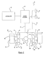
- FIG. 2 is a block diagram of the brake system arranged in accordance with the principles the present invention;
- FIG. 3 is a perspective view of the golf car support frame and components of the brake system;
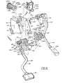
- FIG. 4 is an assembled view of the brake and accelerator pedal assembly;
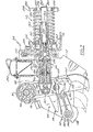
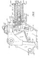
- FIG. 5 is an exploded view of the brake pedal and the accelerator pedal assembly;
- FIG. 6 is a top view of the brake pedal and accelerator pedal assembly;
- FIGS. 7 and 8 are a partial, vertical sectional views of the brake pedal and accelerator pedal assembly;
- FIG. 9 is a graph depicting hydraulic pressure as a function of brake pedal displacement;
- FIG. 10 is a block diagram of a brake system of the present invention utilizing a drum brake system;
- FIG. 11 is a block diagram of the brake system of the present invention utilizing a brake band system;
- FIG. 12 is an interior perspective view of a hub and caliper assembly;
- FIG. 13 is an exterior perspective view of a hub and caliper assembly;
- FIG. 14 is an exploded view of a caliper assembly of FIGS. 12 and 12;
- FIG. 15 is an expanded perspective view of the caliper assembly;
- FIG. 16 is a bottom view of the caliper assembly;
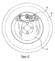
- FIG. 17 as an elevational view of the integral wheel, hub, and rotor assembly;
- FIG. 18 is a perspective view of a brake pedal assembly according to another embodiment of the present invention;
- FIG. 19 is a perspective view, with portions in phantom, of the optional insert member of the brake pedal assembly illustrated in FIG. 18;
- FIG. 20 is a perspective view of an accelerator pedal assembly according to another embodiment of the present invention; and
- FIG. 21 is a perspective view, with portions in phantom, of the optional insert member of the accelerator pedal assembly illustrated in FIG. 20.
- The following description of the preferred embodiments is merely exemplary in nature and is in no way intended to limit the invention, its application, or uses.
- FIG. 1 depicts a
golf car 10 having a brake system arranged in accordance with the principles of the present invention.Golf car 10 includes a pair offront wheels 12 and a pair ofrear wheels 14.Front wheels 12 preferably operate as steering wheels to control the direction of travel ofgolf car 10. Rearwheels 14 preferably function as drive wheels for propellinggolf car 10. -
Golf car 10 includes aseat 16 which preferably accommodates a driver and a passenger.Golf car 10 also includes asteering wheel 18 which controls the direction offront wheels 12. Anaccelerator pedal 82 and abrake pedal 80 enable the operator to control acceleration and braking ofgolf car 10.Accelerator pedal 82 andbrake pedal 80 preferably are suspended from support members which hang generally downwardly from underneath a front cowling 24, as will be described herein. - Still referring to FIG. 1, an entire brake actuator and
release assembly 50 is configured as a modular unit mounted above thefloorboard 26 and at least partially beneath the front cowling 24. It therefore lacks any underhanging components that extend beneath thefloorboard 26. This configuration is advantageous for several reasons. For instance, there is no risk that any components of thebrake system 50 will be damaged by obstructions over whichgolf car 10 may travel. Moreover, the system components are isolated from corrosive substances over which the vehicle may travel such as water, fertilizers, etc. - FIGS. 2 depicts a particular feature of
golf car 10, namely,brake system 50.Accelerator pedal 82 controls operation of anelectric motor 32 which is powered by a source of electrical energy (not shown).Electric motor 32 includes one or a pair of output shafts 34 which control drive to respective hubs 38. It should be noted that reference numerals in the drawings may include an R or L suffix to designate a component as corresponding to the left or driver's side or the right or passenger's side ofgolf car 10. Respective hubs 38 driverear wheels 14 to propelgolf car 10. Whilemotor 32 is described herein as an electric motor, one skilled in the art will recognize thatrear wheels 14 may be propelled by a gasoline powered engine and transmission or other suitable power source. -
Brake system 50 will generally be described herein as a hydraulically actuated brake system wherein displacement ofbrake pedal 80 generates a hydraulic force to operate a braking element, such as a disk, drum, or band brake system, as will be described herein.Brake system 50 includesbrake pedal 80 which connects to and displaces alinkage 42.Linkage 42 provides an input to amaster cylinder 60.Master cylinder 60 operates generally as a conventional master cylinder in which depressingbrake pedal 80 provides an input tomaster cylinder 60 which generates an increase in hydraulic fluid pressure output onhydraulic control line 46. -
Hydraulic control line 46 provides fluid pressure tocaliper assemblies 48. Eachcaliper assembly 48 includes opposingpads 44. A brake rotor 40 moves rotationally in accordance with hubs 38.Pads 44 apply a frictional force to brake rotor 40 to retard movement ofbrake disk 52, thereby applying a braking force uponwheels 14.Caliper assemblies 48 thus operate generally as is known to one skilled in the art. In order to maximize braking force, an optional second pair ofcaliper assemblies 54 may be arranged to provide additional retarding force upon brake rotor 40. A particularly attractive feature of utilizing two caliper assemblies on a single brake disk is to compensate for space limitations inherent with the generally small diameter ofwheels 14 of atypical golf car 10. - As described above,
depressing brake pedal 80causes master cylinder 60 to generate a hydraulic fluid output pressure onhydraulic control line 46 which is applied tocaliper assemblies 48 and tocalipers assemblies 54 if present. An increase in hydraulic fluid pressure causesbrake pads 44 to move toward brake rotor 40 to generate a frictional force which retards movement ofwheels 14. -
Brake system 50 has two modes of operation. A first mode of operation, a service mode, ofbrake system 50 reduces the speed ofgolf car 10 to a lower speed, a stop, or to prevent unwanted acceleration ofgolf car 10 when going down hill. A second mode of operation, a parking mode, ofbrake system 50 maintainsgolf car 10 in a stopped position until the parking mode has been released. -
Brake pedal 80 has a range of travel for causingmaster cylinder 60 to output a hydraulic fluid pressure suitable for stoppinggolf car 10 or maintaininggolf car 10 in a stopped position. A first portion of the range of travel ofpedal 80 effects a service mode of operation for reducing the speed ofgolf car 10 or to prevent unwanted acceleration ofgolf car 10 when going down hill.Depressing brake pedal 80 furtherplaces brake system 50 in a parking mode.Linkage 42 includes a detent setting for engaging and holdingbrake pedal 80 in a predetermined position while in the parking mode. When in this parking mode, theaccumulator 62 provides a supplemental input tomaster cylinder 60 to compensate for any hydraulic fluid pressure drop through seal leakage and the like.Accumulator 62 maintains hydraulic fluid pressure so thatcaliper assemblies 48 provide suitable parking brake force upon brake rotor 40 and associatedwheels 14. -
Brake pedal 80 andlinkage 42 cooperate to include a single detent which is engaged whenbrake pedal 80 travels a predetermined distance so as to causemaster cylinder 60 to output a sufficient hydraulic fluid pressure to prevent displacement ofwheels 14. Whenbrake pedal 80 has engaged a detent position to define a parking mode of operation,brake system 50 can be disengaged from the parking mode of operation by depressing eitherbrake pedal 80 oraccelerator pedal 82.Accelerator pedal 82 is mechanically linked tobrake pedal 80 to enable release of thebrake system 50 from the parking mode of operation. - With particular reference to FIG. 3,
golf car 10 includes avehicle frame 56.Frame 56 provides a support to which brake andaccelerator pedal assembly 58 connects.Rear axle assembly 64 supports a rear portion offrame 56 via a suspension (not shown). As shown in Fig. 3, brake andaccelerator pedal assembly 58 mounts to anupper portion 52 offrame 56 so thatbrake pedal 80 is suspended downwardly onlever arm 88 andaccelerator pedal 82 is suspended downwardly uponaccelerator arm 172. - Several features of
brake system 50 will now be described. When the parking mode is engaged, brake system 30 generates a single audible click or pop sound. The sound indicates that the parking mode has been properly engaged by the operator. The benefit of a single audible sound is to provide a clear indication that the parking mode has been engaged. This feature improves upon conventional braking systems where multiple audible sounds may be generated when engaging a parking mode. In such systems the operator could incorrectly assume that while the brake pedal is locked in a position that generates a sufficient braking force, an insufficient parking brake force could be applied. -
Brake system 50 inherently has less hysteresis associated with stiction than brake systems utilizing mechanical components, particularly hysteresis caused by cables running over contact points. Reduced hysteresis provides abrake system 50 which requires less force for selecting either the service or parking modes verses a mechanical system which requires greater force to properly engage a service or parking mode. Because hysteresis is inherently less in a hydraulic system and because hysteresis in mechanical systems typically increases over time,hydraulic brake system 50 significantly reduces hysteresis concerns problem over the lifetime ofgolf car 10. -
Hydraulic brake system 50 has a self-adjusting system which compensates for wear inbrake pads 44. Self adjustment occurs because the system allows extra fluid from the hydraulic reservoir ofmaster cylinder 60 to be added to the system. Using caliper design features well known in the art, the seals of the hydraulic cylinders in the brake calipers insure a uniform return ofbrake pads 44 to equal distances away frombrake disk 52. These benefits may be further realized by utilizing a bladder-based hydraulic reservoir which provides several additional advantages. The bladder type hydraulic reservoir ensures minimal loss of hydraulic fluid through the top of the reservoir. This avoids introduction of contaminants such as water, dirt, and atmospheric transfer which may occur. -
Hydraulic brake system 50 utilizes a synthetic fluid which is non-hygroscopic. A non-hygroscopic fluid does not absorb any fluid. Conventional brake fluid, on the other hand, absorbs moisture directly through rubber hoses and seals and other places where conventional brake systems are open to the atmosphere, including the reservoir. This transfer occurs even through seals which are frequently water vapor permeable. Thus, while many seals resist moisture in a liquid form, many such seals do not resist moisture in the form of a gaseous vapor. Hygorscopic brake fluid also often accelerates internal breakdown of metal brake system parts, while non-hygroscopic, synthetic fluid significantly reduces internal breakdown of metal brake system parts. Non-hygroscopic fluids provide a non-polar property, which yields an environmentally friendly brake fluid. Most grass plants will not absorb the non-hygroscopic, synthetic fluid, while typical conventional brake fluids may be absorbed by and damage plant life yet. - Conventional brake fluids, while possibly avoiding water absorption, also absorb air. The absorption of air into the brake fluid creates a spongy brake feeling and can also raise other issues such as cavitation and outgassing. Outgassing occurs when a vehicle remains exposed for a lengthy period of time in a high altitude condition. Bringing the golf car down to lower elevations and thus higher atmospheric pressure causes air entrained in the liquid at higher elevations to boil off at the lower elevations. This introduces variation into the hydraulic system.
-
Hydraulic brake system 10 also provides a positively-sealed, pressurized hydraulic brake system. In a parking mode,hydraulic brake system 10 generates at least 750 pounds per square inch (PSI). This pressurization exceeds internal hydraulic fluid pressure typically utilized in conventional hydraulic braking systems, particularly at rest. In conventional hydraulic braking systems, the parking mode is engaged through a mechanical-type emergency brake or transmission lock.Brake system 50 utilizes a hydraulic system which is continuously pressurized when the golf car is not in use and the brake system is engaged in a parking mode. To achieve a positive seal in response to relatively high static hydraulic pressures present inbrake system 50, elastomeric seals replace metal-to-metal contact on all sealing surfaces, including air bleeder valves found oncaliper assemblies 48. -
Hydraulic brake system 50 also includes a damping systems to provide a controlled release ofbrake pedal 82. The damping system utilizes a dampened hydraulic fluid flow to maintain a controlled return ofparking brake 82 pedal to its non-operative position. This controlled rate of upward movement minimized noise inherent in the stopping of brake pedals at the top of travel in conventional brake systems. - Hydraulic fluid travels through a spiral grooved return path to restrict hydraulic fluid flow during pedal return. The fluid damping path enables a fluid flow return rate which encourages the brake pedal upward at a reasonable rate so as to maintain contact with the foot of the operator while the operator lifts upward with his or her foot. Thus, the operator feels the brake pedal firmly on the bottom of the operator's foot, while the return rate is sufficiently slow to prevent banging when the brake pedal reaches the top of travel.
- Referring now to FIGS. 4-8, a preferred mode of practicing the invention will be described. The brake actuator and
release assembly 50 includes as its major components 1) amaster cylinder 60, 2) ahydraulic accumulator 62, and 3) an integrated brake pedal andaccelerator pedal assembly 58. All of these components are mounted on acommon support bracket 66 that is formed from a single metal stamping. As best seen in FIGS. 4-8, thesupport bracket 66 has an open rear end, inboard andoutboard sidewalls front wall 72 connecting thesidewalls flanges sidewalls front wall 72 for connection to a support such as thefront wall 42 of the operator's compartment. - The integrated brake pedal and
accelerator pedal assembly 58 and thehydraulic accumulator 62 can be used either in combination or independently of one another and are applicable to the illustratedbrake system 50 as well as to a variety of other systems. Each of these components will be described in turn. - The integrated brake pedal and
accelerator pedal assembly 58 is usable with thehydraulic brake system 50 as well as a more traditional mechanical cable-actuated brake system. It includes abrake pedal 80, anaccelerator pedal 82, and alocking mechanism 84. Theassembly 58 can perform several distinct functions. First, thebrake pedal 80 can be actuated to perform a service braking operation. Second, thelocking mechanism 84 can latch thebrake pedal 80 in a locked, actuated position to hold theservice brakes 52 in their engaged position. Third, thebrake pedal 80 can operate, in conjunction with theaccumulator 62, to facilitate brake pedal latching and store energy to help assure that thebrakes 52 will remain in their locked position despite creep that may occur within the system. Fourth, thelocking mechanism 84 can be released using either thebrake pedal 80 or theaccelerator pedal 82 without actuating any secondary brake release mechanism. - The
brake pedal 80 includes apivot shaft 86, alever arm 88 extending downwardly from thepivot shaft 86, and apad 90 mounted on the bottom end of thelever arm 88. As best seen in FIGS. 6, 7, and 8, thepivot shaft 86 is mounted on a plastic sleeve 92 so as to be rotatable with respect thereto, and the plastic sleeve 92 is, in turn, mounted on amain pivot shaft 94.Shaft 94 is rotatably supported on thesupport bracket 66 and also serves as the pivot shaft for the accelerator pedal 82 (discussed below). Thelever arm 88 preferably is formed from steel encased in a plastic sleeve (not shown) in order to protect the steel from corrosion. Thepad 90 may comprise any suitable foot actuated pad mounted on the end of thelever arm 88. Atorsion spring 96, serving as a brake pedal return spring, is mounted on thepivot shaft 86 on one side of thelever arm 88. In addition, aplastic block 98 is mounted on the upper surface of thelever arm 88 to form part of thelock mechanism 84 as detailed below. - Referring particularly to FIG. 5, a master cylinder actuating
pin support arm 100 is mounted on thepivot shaft 86 adjacent the inboard side of thelever arm 88 so as to rotate with thelever arm 88. Anactuating pin 102 is mounted on thesupport arm 100 so as to rotate with thepivot shaft 86. Thepin 102 is coupled to amain piston 104 of themaster cylinder 60 via aroller 103 and a strap 105 so that thebrake pedal 80 andmaster cylinder piston 104 always move together. Theactuating pin 102 comprises an eccentric pin that is mounted in anaperture 106 in thesupport arm 100 so as to extend laterally toward thebrake lever arm 88. Ahead 108 on thepin 102 can be rotated to rotate the thicker portion of theeccentric pin 102 either towards or away from the master cylindermain piston 104, thereby eliminating any play or dead space between thebrake pedal 80 and the master cylindermain piston 104 after assembly of all components. - The
locking mechanism 84 is operable to automatically latch thebrake pedal 80 in its locked position upon depression of thebrake pedal 80 to a latch point and to automatically unlatch thebrake pedal 80 from its locked position to release thebrakes 52 upon brake pedal over travel beyond the latch point. Thelocking mechanism 84 also is configured to release thebrake pedal 80 under power of theaccelerator pedal 82. Thelocking mechanism 84 may comprise any structure having at least one of 1) single point latching capability, 2) the ability to release thebrakes 52 upon brake pedal over travel beyond its latched position, and 3) a kickoff mechanism that permits accelerator pedal release of thebrake pedal 80. The illustratedlocking mechanism 84 includes theblock 98 on the brakepedal lever arm 88, acontrol arm 110 pivotally mounted on thebrake pedal 80, aswing arm 112 pivotally mounted on thesupport bracket 66, and anover-center spring 114 that is coupled to thecontrol arm 110 and to theswing arm 112 so as to bias theswing arm 112 downwardly during service braking and to bias theswing arm 112 upwardly during a latch and release cycle. - The
control arm 110 comprises a metal plate pivotally mounted on theblock 98 of thebrake pedal 80 via a pivot pin.Control arm 110 has inner and outer faces and front and rear ends. The rear end presentsdetents 118 and 120, and alug 122 is mounted on the outer face near the rear end near the axis of the pivot pin. During a brake lock and release cycle,detents 118 and 120 cooperate with a dog or pawl 124 on theswing arm 112. A cushioned stop is mounted on the inner face of thecontrol arm 110 in front of the pivot pin. The stop has first and second arcuate surfaces that selectively engage corresponding first and second cushioned posts on theblock 90 during the brake pedal lock and release cycle as detailed below. Finally, apost 136 extends outwardly from a front end portion of the outer face of thecontrol arm 110 for connection to a front end of theover-center spring 114. - The
swing arm 112 supports the dog 124 and the cam 125. It also supports acam follower 138 that rides along acam 140 on theblock 98. Theentire swing arm 112 is mounted on apivot tube 142 that extends laterally across thesupport bracket 66 and that is rotatably supported on asupport pin 146.Support pin 146 is, in turn, mounted in apertures in the opposedsidewalls support bracket 66. A pair of camfollower support arms 144 extend forwardly from thepivot tube 142 in a spaced-apart relationship. Thecam follower 138 is rotatably mounted on the front ends of thesupport arms 144, and a cushionedelastomeric bumper 148 is mounted on the rear ends of thesupport arms 144. Thecam follower 138 comprises a roller mounted on thesupport arms 144 by a roll pin. Thebumper 148 serves as a stop for thebrake pedal 80 when the brake pedal is in its at rest or fully released position seen in FIG. 7. The dog 124 is positioned laterally outwardly of the outboard camfollower support arm 144 and is configured to cooperate with thedetents 118 and 120 on thecontrol arm 110. The cam 125 is formed from a common stepped lug with the dog 124 and is positioned so as to be engaged by thelug 122 on thecontrol arm 110 during a latching operation. Aspring support bracket 150, disposed outboard of the dog 124, supports apost 152 to which theover-center spring 114 is connected. The locations of theposts swing arm 112 and thecontrol arm 110 are selected relative to 1) one another, 2) the rotational axis of the cam follower, 3) the pivot axis of thebrake pedal 80, and 4) the pivot axis of theswing arm 112 to cause thespring 114 to move across the pivot axis of theswing arm 112 at selected phases of the brake pedal depression and return processes so as to selectively assist brake pedal locking and unlocking. In the illustrated embodiment, the over-center spring is 30°-40° below the horizontal when it is in its first over-center position and a corresponding amount above the horizontal when it is in the second over-center position. - The
block 98 is mounted directly on the upper surface of the brakepedal lever arm 88 and serves as a support structure for several other components of thelocking mechanism 84. It has thecam 140 formed directly on the upper or rear surface thereof. Thecam 140 is straight along the majority of its length but has anarcuate portion 154 at its lower end surface formed from a cutout in theblock 98. Arcuate portion is dimensioned such that thecam follower 138 will rest in thearcuate portion 154 in a locked position of thebrake pedal 80. - A generally L-shaped
toggle arm 156 is pivotally mounted on the inner lateral surface of theblock 98 adjacent theswing arm 112. Thetoggle arm 156 includes 1) a first leg 158 and 2) asecond leg 160 that extends generally orthogonally from the first leg 158. The first leg 158 is biased into contact with a post 162 on theblock 98 by a return spring 164. Thesecond leg 160 cooperates selectively with alug 166 on theswing arm 112 so as to prevent swing arm pivoting motion during the initial phase of brake pedal depression and to subsequently permit theswing arm 112 to fall into its locking position when thelug 166 clears thesecond leg 160, thus allowing only one contact sound to be heard. - Finally, a
kickoff arm 170 is mounted on the inboard end of thepivot tube 142 at a location beyond the inboard camfollower support arm 144. Thekickoff arm 170 extends forwardly and outwardly from thepivot tube 142 so as to extend beyond theinboard sidewall 70 of thesupport bracket 66 and so as to be engaged by theaccelerator pedal 82 upon initial accelerator pedal depression. - The
accelerator pedal 82 is mounted on the inner distal end of thepivot shaft 94 at a location outside of theinboard sidewall 70 of thesupport bracket 66. It includes 1) alever arm 172 that extends downwardly from thepivot shaft 94 and 2) apad 174 that is mounted on the distal end of thelever arm 172. A portion of thelever arm 172 is positioned closely adjacent thekickoff arm 170 so as to engage thekickoff arm 170 upon initial accelerator pedal depression. In addition, a non-contact acceleratorpedal position sensor 178 is positioned inside thelever arm 172 in order to provide an indication of accelerator pedal actuation. Theaccelerator pedal 82 is biased to its deactuated position by areturn spring 180. - In operation, the integrated brake pedal and
accelerator pedal assembly 54 assumes the position illustrated in FIGS. 5-6 when thebrakes 52 are not engaged. At this time, thebrake pedal 80 assumes an at rest or fully released position in which it is pivoted to its rearward-most extent in which the front face on theblock 98 engages thebumper 148 on theswing arm 112. Thecam roller 138 on theswing arm 112 is located at its maximum possible distance from thearcuate portion 154 of thecam 140. In addition, theover-center spring 114 is in its first over-center position in which it biases thecontrol arm 110 to the position in which its centerline is beneath the pivot axis of theswing arm 112. It therefore biases theswing arm 112 downwardly. - Next, the operator engages the
brakes 52 by pressing downwardly on thepad 90 to swing thebrake pedal 80 clockwise into a service braking position. This pivoting motion causes the mastercylinder actuating pin 102 to drive theroller 103 and master cylindermain piston 104 forwardly to effect service braking. After the service braking stroke ends, but before thebrake pedal 80 reaches it latch point, thelug 166 on theswing arm 112 rides along thesecond leg 160 of thetoggle arm 156 to hold thecam roller 138 away from thecam face 140 and to hold the dog 124 and cam 125 on theswing arm 112 away from the control arm. As a result, service braking and subsequent brake pedal depression toward the latch point occur without contact between the latching components of thelocking mechanism 84, thereby avoiding the generation of contact sounds that otherwise could give a false audible indication of pedal locking. Theover-center spring 114 remains in its first over-center position at this time. Thecontrol arm 110 therefore remains in the position in which it cannot latch against theswing arm 112. As a result, thebrake pedal 80 will return to its released position if the operator removes his foot from thepad 90 without additional brake pedal depression. - At the end of service braking stroke and well beyond it, the
lug 166 on theswing arm 112 clears thesecond leg 160 of thetoggle arm 156 so that theswing arm 112 drops through an arc to a position in which the cam 125 engages thelug 122 on thecontrol arm 110. This delayed dropping of theswing arm 112 has several benefits. For instance, as described above, it permits the dog 124 and cam 125 on theswing arm 112 to clear thedetents 118 and 120 and thedog 122 on thecontrol arm 110 so as to prevent a false audible indication of brake pedal locking. Moreover, it prevents theswing arm 112 from swinging towards its locked position until theover-center spring 114 is stretched sufficiently to store enough potential energy to effectively assist in swing arm movement into its locked position. In addition, the solid contact between the cam 125 and thelug 122 that occurs when theswing arm 112 drops into place produces a distinctive "clicking" sound that provides an audible indication to the operator that thebrake pedal 80 has moved into a position in which it can be locked. - When the operator releases his foot from the
brake pedal 80 after depressing it to its locked position, the brake pedal returns a very small amount to permit theover-center spring 114 to move from its first over-center position to the second over-center position as a result of the swing arm cam 125 pushing thecontrol arm dog 122. As a result of this movement, thecontrol arm 110 pivots rapidly from this position to the latched position. Because thedog 122 is located very close to the pivot axis of thecontrol arm 110, a very small range of axial brake pedal movement (on the order of a few thousands of an inch) results in 60° or more of control arm pivoting movement. This relationship reduces the work required of theover-center spring 114 during the latching process. The second face 130 on the stop 126 now engages the second post 134 on theblock 98, and the first or lower detent 118 on thecontrol arm 110 now engages the dog 124 on theswing arm 112 to lock theswing arm 112 in position. This motion provides a distinctive clicking sound that provides an audible indication to the operator that thebrake pedal 80 has been locked. Thebrake pedal 80 will thereafter remain in the locked position under the latching force of thecontrol arm 110 when the operator releases thebrake pedal 80. However, because thespring 114 is now in is second over-center position in which its centerline is above the pivot axis of thecontrol arm 112, it biases thecontrol arm 112 upwardly rather than downwardly, thereby priming thecontrol arm 112 for subsequent release. - The holding force applied on the
control arm 110 by theover-center spring 114 at this time should be large enough so as not to be overcome by any force that might inadvertently be placed upon or generated through theaccelerator pedal 82 by virtue of the vehicle 30 being jostled during shipment or by rough treatment by errant operators. However, this holding force need not be very large because any moment arm which might tend to cause theswing arm 112 to swing out of its locked position is very small. As a result, a relatively weak spring (having a spring load on the order of 8-12 lb can be used as theover-center spring 114. - The
brakes 52 may be released by operating either thebrake pedal 80 or theaccelerator pedal 82 to unlatch thebrake pedal 80 from its locked position. To release the brakes using thebrake pedal 80, all the operator need do is depress thepedal 80 beyond its locked position to an over travel position. This brake pedal movement and consequent swing arm movement will cause the dog 124 on theswing arm 112 to slip out of the first detent 118 on thecontrol arm 110, permitting theover-center spring 114 to pull theswing arm 112 upwardly so that dog 124 snaps against thesecond detent 120 as seen in FIG. 10. The snapping action of the dog 124 against thedetent 120 produces a distinctive click that apprises the operator that thebrake pedal 80 is unlatched. As a result, thebrake pedal 80 will return to its at-rest position under the biasing forces of thereturn spring 96 and theaccumulator spring 246 when the operator releases thebrake pedal 80. - The
brake pedal 80 places a substantial moment on theswing arm 112 during the return stroke of thebrake pedal 80. The dog 124 on theswing arm 112 produces a corresponding moment on the upper surface of thedetent 120 of sufficient magnitude to pivot thecontrol arm 110 counter-clockwise. Theover-center spring 114 therefore moves back to its first over-center position so that it again biases theswing arm 112 downwardly. In addition, thelug 166 on the inner lateral surface of theswing arm 112 engages thesecond leg 160 of thetoggle arm 156 during the return stroke to cause thetoggle arm 156 to pivot clockwise to permit unobstructed movement of thelug 166 past thetoggle arm 156. Thetoggle arm 156 then drops back into its initial position under the biasing force of the spring 164 so that it is primed for the next service braking cycle. - Brake pedal release using the
accelerator pedal 82 occurs in similar sequence. The operator presses downwardly on theaccelerator pedal 82 so that thelever arm 172 engages thekickoff arm 170. This engagement forces theswing arm 112 to swing clockwise about thepivot tube 142 to drive thecontrol arm 110 to pivot as described above. As before, this movement unlatches theswing arm 112 from thecontrol arm 110 and permits thebrake pedal 80 to return to its at-rest position under the biasing force of the brakepedal return spring 96 and theaccumulator spring 246. Also as before, this movement forces thecontrol arm 110 andover-center spring 114 back to the initial position. Because thecutout 154 in thecam surface 140 is tangential to the swing arm pivot arc, thecam roller 138 simply moves circumferentially along thecam surface 140 during the initial, accelerator pedal imposed phase of the unlatching operation without resistance from the rather substantial return force imposed on thebrake pedal 80 by the brakepedal return spring 96 and theaccumulator spring 246. Brake pedal unlatching therefore imparts little resistance to accelerator pedal motion, andbrakes 52 are disengaged after the first 1-3 inches of accelerator pedal stroke with minimal operator effort. As a result, the operator can "feather" accelerator pedal motion so that thebrakes 52 can be disengaged without over-depressing theaccelerator pedal 82. This eliminates jerky motion or quick starts often associated with golf carts and other light-duty vehicles. - The
master cylinder 60 andhydraulic accumulator 62 are configured to translate the mechanical actuating forces generated by brake pedal depression into hydraulic pressure that first engages thebrakes 52 and that then stores additional energy for holding thebrakes 52 in their engaged condition. This energy storage provides several benefits. For instance, it permits thebrake system 50 to make up for "creep" or fluid pressure loss that may occur due, e.g., relaxation of elastomeric components of the system. Moreover, it can assist in returning thebrake pedal 80 to its at rest position following release of a locked brake pedal. - Referring to FIGS. 4, 5, 7, and 8, the
master cylinder 60 is generally conventional. It includes a housing 200 having an internalhorizontal bore 202 formed therein. Areservoir 204 is formed above thebore 202 for storing hydraulic fluid. Thebore 202 has anupper fill inlet 206 and arear outlet 208. Theinlet 206 cooperates with thereservoir 204. Therear outlet 208 opens into an accumulator chamber 210, detailed below. The master cylindermain piston 104 is slidably mounted in thebore 202 so as to extend rearwardly from the rear end of thebore 202 and into contact with theroller 103. As a result of this arrangement, 1) depression of thebrake 80 and consequent swinging movement of theactuator pin 102 androller 103 drives themain piston 104 forwardly through thebore 206 to pressurize theoutlet 208, and 2) release of thebrake pedal 80 permits themain piston 104 to move rearwardly through thebore 202 to depressurize theoutlet 208. - Referring to Fig. 7, accumulator chamber 210, as well as the remainder of the
accumulator 62, may be located at any pressurized point in thebraking system 50. In the illustrated embodiment, however, the chamber 210 is formed in anextension 212 of the master cylinder housing 200 extending essentially colinearly with thebore 202 so as to reduce the number of parts in theaccumulator 62 and to facilitate assembly. The accumulator chamber 210 has a first orifice 218 in a rear wall thereof that opens directly into themaster cylinder outlet 208, and asecond orifice 220 in an upper wall thereof that communicates with ableeder port 222 and abrake supply orifice 224 in the mastercylinder housing extension 212. Theorifice 224 is connected to the front and/orrear vehicle brakes 52 via associatedbrake lines 46 of Fig. 2. - An
accumulator drive piston 214 and a one-wayrestrictor valve 216 are mounted in the accumulator chamber 210. Theaccumulator drive piston 214 is slidably mounted in the chamber 210 so as to extend beyond a rear end of themaster cylinder extension 212 and into contact with theaccumulator spring assembly 58. The one-way restrictor valve is positioned forwardly of theaccumulator drive piston 214 and is biased toward the front of the chamber 210 by a return spring that is seated on the one-wayrestrictor valve 216 at its front end and on theaccumulator drive piston 214 at its rear end. - The purpose of the one-way
restrictor valve 216 is to damp return fluid flow into themaster cylinder 60 from the accumulator chamber 210 upon release of thebrakes 52, thereby inhibiting the pronounced brake pedal snapback effect exhibited by most park and hold brake systems of this type. The energy stored in theaccumulator 62 and thebrakes 52 instead is released more gradually, permitting a much smoother brake pedal return. - The
hydraulic accumulator 62 performs several beneficial functions. For instance, it reduces the effort required by the operator to depress thebrake pedal 80 to its locked position. It also stores energy generated upon manual pressurization of the hydraulic fluid in a form that can then be used to maintain thebrakes 32 in their engaged positions after thebrake pedal 80 is locked. Finally, it assists in returning thebrake pedal 80 to its released position upon brake pedal unlocking. The preferred accumulator structure is one that has a minimum number of components and that can be readily assembled as a unit offsite and then attached to the remainder of thebrake assembly 50 by an unskilled operator. Towards these ends, thehydraulic accumulator 62 is a spring type accumulator taking the form best seen in FIG. 7. It includes a retainer 240, amovable compression plate 242 disposed at the rear end of the retainer 240, acap 244 affixed to the front end of the retainer 240, and acompression spring 246 captured between thecompression plate 242 and thecap 244. - The retainer 240 includes a front mounting
plate 248 and a plurality (preferably two)straps 250 that extend rearwardly from the mountingplate 248. The mountingplate 248 has an internally threadedpost 252 and a pair oftangs 254 located radially outside of thepost 254 and bent in opposite directions. The threadedcenter post 252 screws onto external threads 256 on the mastercylinder housing extension 212, and thetangs 254 lock intoslots 258 in thefront wall 72 of thesupport bracket 66 when thepost 252 is fully tightened onto the mastercylinder housing extension 212. Theaccumulator 62 can subsequently be unscrewed from the mastercylinder housing extension 212 only by overtorquing theaccumulator 62 in a counter-clockwise direction to release thetangs 254 from theslots 258. Thestraps 250 serve as mounts for thecap 244 and are configured to guide and support both thespring 246 and thecompression plate 242. Eachstrap 250 extends rearwardly from the mountingplate 248 and terminates in ahook 260 at its distal end. The bodies of thestraps 250 serve as supports and guides for thecompression plate 242 and thespring 246. Thehooks 260 latch onto thecap 244 as detailed below to fix the cap in place. - The
compression plate 242 includes a rear annularspring support portion 262 and a cup portion 264. The cup portion 264 extends axially forwardly from the center of the rearspring support portion 262 to a front nut portion 266.Spring support portion 262 presents a seat for the rear end of theaccumulator spring 246. Cup portion 264 is configured to surround the end of the mastercylinder housing extension 212 and to abut the front end of theaccumulator drive piston 214. Apertures 268 are formed in thespring support portion 262 for passage of thestraps 250. Upon assembly, this relationship between thestraps 250 of the retainer 240 and the apertures 268 in thecompression plate 242 permits thecompression plate 242 to move axially relative to the retainer 240 but prevents relative rotational movement between thecompression plate 242 and the retainer 240. - The
cap 244 comprises a metal annular ring having a circular axially front end portion 270 and inner and outercircular flanges 272 and 274. Theflanges 272 and 274 extend rearwardly from the front end portion 270 so as to form a groove serving as a second seat for thespring 246. A pair of hook receiving apertures are formed in the front end portion 270 adjacent to corresponding notches 278. The notches 278 are configured to receive thestraps 250 and thehooks 260 of the retainer 240, thereby locking thecap 244 onto the retainer 240. - The
spring 246 is precompressed a substantial amount as a result of a preassembly process. As discussed in more detail below, this spring precompression sets a threshold pressure below which substantially all work performed by themaster cylinder 60 is applied toward fluid pressurization and above which the majority of the work performed by themaster cylinder 60 is applied toward energy storage in theaccumulator 62. The amount of precompression required for a particular pressurization threshold level will vary depending on the spring rate of thespring 246 and its caged height. Thespring 246 of the illustrated embodiment has a free length of about 9" and a spring rate of 25 Ibs/in. It is precompressed to an installed length of approximately 4" during the assembly process to provide a threshold pressure of about 800-850 psi. - The precompression of the
accumulator spring 246 is selected to set the threshold pressure to a level well above the lockup point of thebrakes 52 but well below the single latch point of thebrake pedal 80. In a system in which the brake pedal is latched in position 8" into its stroke, service braking is performed in the first 2 to 3" of brake pedal stroke even under panic stop conditions. In fact, brake lockup typically occurs after no more than 2-1/2" of brake pedal stroke. Typical lockup points for fully burnished and unburnished brakes are denoted as such in FIG. 8. - Additional brake pedal depression past the
threshold point 286 compresses theaccumulator spring 246, thereby storing the energy of master cylinder actuation in the form of potential energy in thespring 246. System pressure rises at a much slower rate during this phase of pedal actuation, as represented by theshallow portion 288 of thecurve 282. This effect results from the fact that the incremental increase in input force required to compress thespring 246 is substantially lower than the incremental increase in input force required to additionally pressurize the hydraulic fluid. As a result, resistance to brake pedal movement during this second phase of brake pedal actuation increases at a much slower rate than during the first phase. - In the illustrated embodiment, the
transition point 286 between the first and second phases of brake pedal actuation occurs at approximately 800-850 psi of hydraulic pressure. Pressure thereafter rises gradually to about 900-950 psi when thebrake pedal 80 is latched in its locked position and the end of the second phase of its actuation stroke. Thecompression spring 246 is compressed about 1/2" at this time. At least 50%, and possibly at least 65% or more, of the total pedal stroke required to latch thebrake pedal 80 in its locked position is consumed in the second phase of brake pedal actuation. As a result, by the end of this phase, more than ample energy is stored in theaccumulator 62 to hold thebrakes 52 and to return thebrake pedal 80 with little additional effort by the operator. (The amount of energy stored by theaccumulator 62 is represented by the hatchedarea 292 under thecurve 282 in FIG. 9.) - Considerable work is performed over the rather lengthy second phase of the brake pedal actuation stroke, but at much lower input forces than would be required to perform the same amount of work (and hence to store the same amount of energy) over a shorter stroke. In fact, the
transition point 286 is reached at an operator input force of about 35 Ibs, and only an additional 25 Ibs of input force is required to depress thebrake pedal 80 to its latch point. This is in contrast to the drastically higher input force that would be required to pressurize the fluid to a much higher level if the operator were to press thebrake pedal 80 to its latch point without an accumulator in the system (see thephantom line 290 in FIG. 9). Hence, theaccumulator 62 greatly facilitates brake pedal latching and reduces the precision required to achieve the latch point because the operator strokes the pedal a great distance easily. - Upon brake pedal release, the one-way
restrictor valve 216 immediately seats against the front end of the chamber 210 under the force of thereturn spring 230, thereby preventing rapid depressurization of the accumulator chamber 210. The damping effect provided by this restricted fluid flow imposes a relatively low return speed on thebrake pedal 80 that continues for a period of time. Thebrake pedal 80 consequently returns to its initial position without any undesirable rapid snapback that otherwise would produce substantial wear and tear on the system and even risk injury to the operator. The damping grease between the brakepedal pivot shaft 86 and the stationary sleeve 92 additionally damps brake pedal return movement at this time. However, the combined damping effect provided by the one-wayrestrictor valve 216 and the damping grease does not overly-damp brake pedal return. Instead, thebrake pedal 80 is biased by thesprings elastomeric bumper 148 on theswing arm 112 when thebrake pedal 80 reaches its at-rest or fully released position, resulting in a virtually noiseless and vibration less pedal return. - FIG. 10 depicts a
hydraulic brake system 310 arranged similarly tohydraulic brake system 50 of FIGS. 1-3.Hydraulic brake system 310 utilizes a drum brake system rather than a disk brake system to apply braking force at the wheels. Components ofhydraulic system 310 which are similar to the components described with respect to FIGS. 1-3 will be referred to using identical reference numerals. - Of particular interest in FIG. 10,
brake system 310 is embodied as a drum brake system which includes a brake cylinder and shoe assembly 312 which operates in response to hydraulic fluid pressure applied throughhydraulic control line 46. Brake cylinder and shoe assembly 312 includes a brake cylinder which presses brake shoes radially outward against brake drum 314. Brake drum 314 on its outboard side connects towheels 14. Application of hydraulic fluid pressure throughhydraulic control lines 46 causes brake cylinder and shoe assembly 312 to press against brake drum 314, thereby generating a frictional force retarding movement ofwheels 14. Accordingly,hydraulic brake system 310 operates as described above, except that application of braking pressure occurs through a drum brake system rather than through a disk brake system. - In yet another embodiment of the present invention, FIG. 11 depicts a
hydraulic brake system 320 which utilized a band brake system to retard movement of drive shafts 34. FIG. 11 is generally arranged as described above with respect to FIGS. 1-3 and 10 except that the brake mechanism will be described with respect to a band brake system, rather than a disk or drum brake system. Accordingly, like reference numerals from these figures will be used to described similar components in FIG.11. -
Hydraulic brake system 320 utilizes displacement ofbrake pedal 80 andlinkage 42 to generate a hydraulic fluid pressure frommaster cylinder 60 into hydraulic control lines 46.Hydraulic control lines 46 operate a band brake assembly 322. Band brake assembly 322 includes a brake cylinder 324 rigidly connected to drive shaft 34. Brake cylinder 324 is encircled by brake band 326. In response to hydraulic to fluid pressure, brake band 326 circumferentially restricts around brake cylinder 324 to generate a frictional force. A frictional force retards movement of drive shafts 34 and correspondingly retards movement ofwheels 14 to thereby crate a braking force. When hydraulic fluid pressure inhydraulic control line 46 is reduced, brake band 326 reduces the circumferential constriction thereby reducing the braking force. - FIGS. 12-17 show a preferred embodiment of
caliper assembly 48 and its interconnection togolf car 10. FIG. 12 shows aleft brake assembly 500L which is composed of the integral hub androtor assembly 502 which has arotor portion 504 and awheel hub portion 505.Brake assembly 500L further has acaliper assembly 506 which is attached by two throughbolts 508 to affixedflange 510 rigidly mounted to therear axle housing 511. -
Caliper assembly 506 has a caliperoutboard half subassembly 512 and a caliperinboard half subassembly 514. Caliperinboard half 514 has aninput fluid port 516 for receiving fluid from thehydraulic brake line 521 and afluid output port 517 for providing fluid to theright brake system 500R (see Fig. 13). Caliperinboard half subassembly 514 has ableeder valve 518 for bleeding air from thebrake lines 521 during repair or installation. - FIG. 13 shows a
right brake assembly 500R, which is composed of the same components as those shown in theleft brake assembly 500L of Fig. 12, in mirror image form.Caliper assembly 506 holds a pair ofbrake pads rotor 504 of the integrated hub androtor assembly 502.Pads port 516R. The integrated hub androtor assembly 502 is held ontodrive shaft 536 by ahex castle nut 538 andcotter pin 540. - FIG. 14 shows an exploded view of
caliper assembly 506, which reveals that the caliper inboardhalf subassembly 514 and caliper outboard half subassembly 512 each have a pair ofpiston actuators 520. Each actuator has a conventional polymeric outsideseal 522, which elastically deforms when the pistons are moved forwardly to press against thebrake pads rotor portion 504 when the fluid pressure is removed. Between the halves of thecaliper 506 is a pair of conventional elastomeric O-rings 525 which function to help prevent leakage of hydraulic fluid moving through internal passages within eachhalf sub assembly caliper 506. Disposed immediately adjacent the O-rings 225 is a pair of through holes 528 for accepting through mounting bolts 530 (not shown) (in FIG. 14). Also shown is throughbolt 532 which functions to securebrake pads rotor portion 504. Wire spring clips 542 and 544 generally are further provided to hold the brake pads in place. - FIG. 15 is a perspective view of
caliper assembly 506 of the current invention. Shown are the throughbolts 530 which function to hold the caliper inboardhalf subassembly 514 and caliper outboard half subassembly 516 together. Also shown are throughbolts 532 holding thebrake pads piston actuators 520. - FIG. 16 shows a bottom view of the
caliper brake assembly 500. Shown is the relationship of thepads pistons 520. As can be seen, thepads rotor portion 504 is located. - FIG. 17 is a diagram of the integral wheel hub and rotor assembly with caliper disposed within the small diameter of the
golf cart wheel 542. As can be seen, thelow profile caliper 506 can fit within the small diameter of the golf cart wheel. The lower profile of thecaliper 506 allows for incorporation of a disk brake system onto a golf cart. - Further details of the
brake caliper assembly 506 will now be described.Subassembly 512 includes a metal caliper housing preferably prepared from an iron or aluminum alloy casting, andsubassembly 514 includes a similarly made metal caliper housing. Each of these caliper housings may be precision-machined to conventional tolerances to have their flat exterior mating surfaces, the through holes, and substantially cylindrical pockets for receiving the brake pistons, that are shown in the FIGS. 12 through 15, formed to proper size. Using conventional techniques, internal passages for hydraulic fluid are formed within caliper housings to provide hydraulic fluid from the inlet port to the backside of the respective brake piston pockets. Flat machined surfaces on the end portions of one caliper housing ofsubassembly 512 match up with and bear tightly against corresponding flat machined surfaces on the caliper housing ofsubassembly 514 when the two mountingbolts 530 are drawn tightly against the rigid mountingflange 510 to which theoverall assembly 506 is rigidly mounted. The side face of mountingflange 510 contacting the adjacent caliper housing ofassembly 512 is parallel to therotor 504. The through holes in the caliper housings for the mountingbolts 530 are perpendicular to these machined surfaces, thus ensuring that faces of the brake caliper pistons are sufficiently parallel to the parallel opposed faces ofrotor 504 to ensure substantially uniform wear onbrake pads - Each through bolt is substantially centrally positioned relative to opposed flat machined surfaces of the end portions of the caliper housings of
caliper subassemblies bolts 530 ensures slight compression of O-rings 525, to eliminate the possibility of any hydraulic leak between the adjacent housings. Since only two bolts are required to mount caliper theassembly 512 toflange 510, minimal effort is required for final assembly to the vehicle axle. This means thatbrake caliper assembly 512 can be fully assembled in a location remote from the final assembly plant for the small utility vehicle, function-tested, and then shipped while filled with hydraulic fluid if desired. -
Caliper assembly 506 has a low compact profile when viewed in side elevation. As best shown in FIG. 17, the clearance between the radially outermost points of caliper housings ofsubassemblies quality mounting bolts 530 and a sufficiently stiff mounting flange to avoid any significant lateral or radial flexing or distortion of the caliper assembly during intense braking, up to and including full rotor/wheel lock-up. In this regard, the outer end portions of caliper housings through which the throughbolts 530 are run, are as shown generally thicker (that is, in the direction of the axis of the rear axle of the vehicle) than they are high (that is, a the radially outward direction from the axis of the rear axle of the vehicle). - The use of two sets of opposing pistons in the opposed
half caliper subassemblies piston actuators 520 insubassembly 512 are slightly angularly spaced apart from one another. By using two spaced-apart brake pistons on each caliper subassembly, a generally oblong, kidney-shaped relatively thick brake pad may be used as shown, thus maximizing the amount of surface area of the brake pad. Its large size helps minimize the rate of brake pad surface wear during repetitive braking over a period of months and years. The oblong brake pads are preferably made in any conventional or suitable manner, with reinforcing a back plate portion as shown, to help ensure minimal deflection and good contact between the rotor surface and brake pad surface, even in the central region of the brake pad between the two brake pistons. Armed with the teachings and illustrations within the present disclosure, the design and construction of compact, low-profile dual piston brake caliper assembly of the present invention with its long-life brake pads need not be further described, since the design and construction of larger, less space-efficient conventional two-piston and four-piston brake caliper assemblies are well understood, and details from those design and construction techniques, where space and compact is not an issue, can be readily adapted into the present environment. - Referring now to FIG. 18, a
brake pedal system 600 is illustrated according to another embodiment of the present invention. It should be understood thatbrake pedal system 600 is intended to be used in conjuction withbrake system 50 as described above.Brake pedal system 600 is generally an injection-molded, one-piece member that incorporates numerous system components into a single part. -
Brake pedal system 600 includes apivot shaft 686, alever arm 688 extending downwardly frompivot shaft 686, and apad 690; all of which are integrally molded in a single unitary member. Preferably, as seen in FIG. 19,brake pedal system 600 further includes anoptional reinforcement member 602 encapsulated within an outerplastic housing 604.Reinforcement member 602 is preferably a steel wireform insert that is preformed such that is follows a predetermined contour that closely conforms to a final shape ofbrake pedal system 600. - During injection molding,
reinforcement member 602 is disposed within a mold cavity such that it is encapsulated so that preferably no metal is exposed to the environment. Preferably,reinforcement member 602 is encapsulated using a glass-fiber reinforced Nylon, which can be easily managed during the injection molding process. This arrangement results in abrake pedal system 600 that is completely corrosion resistant. -
Optional reinforcement member 602 is employed to provide additional structural rigidity inbrake pedal system 600 and to further reinforcebrake pedal system 600 during molding to prevent warpage. It has been found that the brake pedal of golf cars is often exposed to extreme loads from applied foot force and counteracting hydraulic force (in the case of a hydraulic braking system). Such extreme loads are easily accommodated withreinforcement member 602. However, it should be appreciated thatreinforcement member 602 may not be required in cases where additional molded reinforcements are used or moment arms are shorted to reduce loading. - It should further be appreciated that the principles set forth herein are not limited to brake
pedal system 600. That is, as seen in FIGS. 20 and 21, it is intended that anaccelerator pedal system 682 is injection molded using glass-fiber reinforced Nylon. Similar to brakepedal system 600, injection moldedaccelerator pedal system 682 includes an optionalinternal reinforcement member 606 encapsulated by an outerplastic housing 608; however, sinceaccelerator pedal system 682 is not typically exposed to the extreme loading forces common inbrake pedal system 600,internal reinforcement member 606 is not required. However, it is has been determined thatinternal reinforcement member 606 minimizes warpage ofaccelerator pedal system 682 during molding. Therefore, inclusion ofinternal reinforcement member 606 is preferred. - As can be appreciated from FIGS. 18-21,
brake pedal system 600 andaccelerator pedal system 682 have the advantage of eliminating a plurality of otherwise separate components, such as, but not limited to, sleeve 92,pin support 100, andcontrol arm 110 and the associated fasteners and/or processing steps. Furthermore,brake pedal system 600 andaccelerator pedal system 682 have the primary advantages of cost effectively producing an otherwise complicated series of parts into a single member, reducing the weight of the associated systems, improving the aesthetic quality of the vehicle, maximizing corrosion resistance, improving the ease of maintaining tolerances, and eliminating the need for complicated painting, coating, or plating of the pedal assembly. - The description of the invention is merely exemplary in nature and, thus, variations that do not depart from the gist of the invention are intended to be within the scope of the invention. Such variations are not to be regarded as a departure from the spirit and scope of the invention.
Claims (10)
- A golf car comprising:a frame supported on a plurality of wheels;a brake system; anda brake pedal operably coupled to said brake system for actuating said brake system, said brake pedal having an arm pivotally coupled at least indirectly to said frame and a pedal member extending therefrom, said brake pedal being molded such that said arm and said pedal member are integrally molded as a unitary member being generally resistant to corrosion.
- The golf car according to Claim 1, further comprising:a drive system for driving at least one of said plurality of wheels; andan accelerator pedal operably coupled to said drive system for actuating said drive system, said accelerator pedal having an arm pivotally coupled at least indirectly to said frame and a pedal member extending therefrom, said accelerator pedal being molded such that said arm and said pedal member are integrally molded as a unitary member being generally resistant to corrosion.
- The golf car according to Claim 2, further comprising:an internal reinforcement member being encapsulated in at least one of said arm and pedal member of said accelerator pedal.
- The golf car according to Claim 3 wherein said internal reinforcement member is a steel wireform member.
- The golf car according to Claim 1, further comprising:an internal reinforcement member being encapsulated in at least one of said arm and pedal member of said brake pedal.
- The golf car according to Claim 5 wherein said internal reinforcement member is a steel wireform member.
- A golf car comprising:a frame supported on a plurality of wheels;a brake system;a brake pedal operably coupled to said brake system for actuating said brake system, said brake pedal having an first arm pivotally coupled at least indirectly to said frame and a first pedal member extending therefrom, said brake pedal being molded such that said first arm and said first pedal member are integrally molded as a unitary member being generally resistant to corrosion;a drive system for driving at least one of said plurality of wheels; andan accelerator pedal operably coupled to said drive system for actuating said drive system, said accelerator pedal having an second arm pivotally coupled at least indirectly to said frame and a second pedal member extending therefrom, said accelerator pedal being molded such that said second arm and said second pedal member are integrally molded as a unitary member being generally resistant to corrosion.
- The golf car according to Claim 7, further comprising:an internal reinforcement member being encapsulated in at least one of said brake pedal and said accelerator pedal.
- The golf car according to Claim 8 wherein said internal reinforcement member is a steel wireform member.
- A golf car comprising:a frame supported on a plurality of wheels;a brake system;a brake pedal operably coupled to said brake system for actuating said brake system, said brake pedal having an first arm pivotally coupled at least indirectly to said frame and a first pedal member extending therefrom, said brake pedal being injection molded such that said first arm and said first pedal member are integrally molded as a unitary member being generally resistant to corrosion;a first internal reinforcement member being encapsulated in said brake pedal;a drive system for driving at least one of said plurality of wheels;an accelerator pedal operably coupled to said drive system for actuating said drive system, said accelerator pedal having an second arm pivotally coupled at least indirectly to said frame and a second pedal member extending therefrom, said accelerator pedal being injection molded such that said second arm and said second pedal member are integrally molded as a unitary member being generally resistant to corrosion; anda second internal reinforcement member being encapsulated in said accelerator pedal.
Applications Claiming Priority (2)
| Application Number | Priority Date | Filing Date | Title |
|---|---|---|---|
| US10/087,658 US6802232B2 (en) | 2002-03-01 | 2002-03-01 | Brake and accelerator pedals for golf and utility vehicles made of molded plastic |
| US87658 | 2002-03-01 |
Publications (2)
| Publication Number | Publication Date |
|---|---|
| EP1340660A2 true EP1340660A2 (en) | 2003-09-03 |
| EP1340660A3 EP1340660A3 (en) | 2004-06-02 |
Family
ID=27733444
Family Applications (1)
| Application Number | Title | Priority Date | Filing Date |
|---|---|---|---|
| EP03004491A Withdrawn EP1340660A3 (en) | 2002-03-01 | 2003-02-28 | Brake and accelerator pedals for golf and utility vehicles made of molded plastic |
Country Status (8)
| Country | Link |
|---|---|
| US (1) | US6802232B2 (en) |
| EP (1) | EP1340660A3 (en) |
| JP (1) | JP2003341489A (en) |
| KR (1) | KR20030071650A (en) |
| CA (1) | CA2420478A1 (en) |
| MX (1) | MXPA03001795A (en) |
| PL (1) | PL358962A1 (en) |
| TW (1) | TWI262866B (en) |
Cited By (1)
| Publication number | Priority date | Publication date | Assignee | Title |
|---|---|---|---|---|
| CN102602288A (en) * | 2012-03-26 | 2012-07-25 | 常熟市迅达粉末冶金有限公司 | Pressing plate |
Families Citing this family (20)
| Publication number | Priority date | Publication date | Assignee | Title |
|---|---|---|---|---|
| US6796407B2 (en) * | 1999-03-02 | 2004-09-28 | Hayes Brake Llc | Brake system having boosted hydraulic accumulator |
| US6907963B1 (en) * | 1999-03-02 | 2005-06-21 | Hayes Brake Llc | Brake system having hydraulic accumulator and/or combined service brake and park and hold brake |
| US20050072263A1 (en) * | 2003-10-06 | 2005-04-07 | Gibson Jeffrey G. | Automotive foot pedal and method of manufacture |
| JP4234095B2 (en) * | 2004-12-09 | 2009-03-04 | 株式会社エフテック | Automobile operation pedal device |
| US7354354B2 (en) | 2004-12-17 | 2008-04-08 | Integran Technologies Inc. | Article comprising a fine-grained metallic material and a polymeric material |
| JP4928103B2 (en) * | 2005-09-05 | 2012-05-09 | ヤンマー株式会社 | Pedal structure of traveling vehicle |
| US20070138863A1 (en) * | 2005-11-01 | 2007-06-21 | Warren Clark | Modular Pedal Box Assembly |
| KR100805415B1 (en) * | 2006-08-10 | 2008-02-20 | 기아자동차주식회사 | A self locking device of an active headrest |
| JP2010018116A (en) * | 2008-07-09 | 2010-01-28 | Futaba Industrial Co Ltd | Brake pedal device |
| US8587147B2 (en) | 2012-02-17 | 2013-11-19 | Johnson Industries, Inc. | Safety system |
| US9261234B2 (en) | 2012-02-17 | 2016-02-16 | Johnson Industries, Inc. | Safety system |
| WO2014065379A1 (en) * | 2012-10-25 | 2014-05-01 | 本田技研工業株式会社 | Vehicular pedal device |
| US9260088B2 (en) | 2013-10-16 | 2016-02-16 | Ford Global Technologies, Llc | Hybrid brake pedal feel system |
| US20150107401A1 (en) * | 2013-10-23 | 2015-04-23 | The U.S.A. As Represented By The Administrator Of The National Aeronautics And Space Administration | Pedal module for a vehicle having a control-by-wire system |
| US20170043662A1 (en) * | 2014-04-23 | 2017-02-16 | Daryl PERUSIC | Improvements in vehicle mounted pedal box assemblies |
| JP2017021703A (en) * | 2015-07-14 | 2017-01-26 | ヤマハ発動機株式会社 | Pedal unit and vehicle comprising the same |
| CN106740758B (en) * | 2017-01-06 | 2023-07-14 | 风度(常州)汽车研发院有限公司 | Novel anti-intrusion brake pedal |
| CN107176035A (en) * | 2017-07-10 | 2017-09-19 | 安徽理工大学 | A kind of throttle during automobile emergency brake steps on protector by mistake |
| GB2576685B (en) * | 2018-01-17 | 2020-11-04 | Anthony Best Dynamics Ltd | Brake and accelerator robot |
| IT201900013512A1 (en) * | 2019-07-31 | 2021-01-31 | Freni Brembo Spa | DISK BRAKE FOR SERVICE AND HYDRAULIC AND ELECTROMECHANICAL PARKING |
Citations (2)
| Publication number | Priority date | Publication date | Assignee | Title |
|---|---|---|---|---|
| US4598457A (en) * | 1985-08-26 | 1986-07-08 | Allied Corporation | Method of constructing a brake pedal |
| WO2000051860A2 (en) * | 1999-03-02 | 2000-09-08 | Hayes Brake, Llc | Brake system having hydraulic accumulator and/or combined service brake and park and hold brake |
Family Cites Families (46)
| Publication number | Priority date | Publication date | Assignee | Title |
|---|---|---|---|---|
| US1985319A (en) | 1927-12-03 | 1934-12-25 | Charles B Gilmore | Control mechanism |
| US1927209A (en) | 1929-08-21 | 1933-09-19 | Charles B Gilmore | Control apparatus for automobiles |
| US1915286A (en) | 1932-01-09 | 1933-06-27 | Bleustein Ben | Baby carriage brake construction |
| US2551743A (en) | 1948-03-04 | 1951-05-08 | Robert M Huey | Automatic emergency brake release for motor vehicles |
| US2816633A (en) | 1954-06-29 | 1957-12-17 | N A Saigh | Automatic parking brake |
| US2905024A (en) | 1955-08-04 | 1959-09-22 | American Forging & Socket Co | Brake system |
| US2915916A (en) | 1957-07-31 | 1959-12-08 | Bingham Herbrand Corp | Foot actuated mechanism control |
| US3079809A (en) | 1960-03-30 | 1963-03-05 | Universal American Corp | Mechanism control |
| US3511107A (en) | 1968-02-16 | 1970-05-12 | Otsukakoki Kk | Parking brake control devices |
| US3698497A (en) | 1970-07-23 | 1972-10-17 | Bombardier Ltd | Variable speed transmission system and braking means |
| US3822655A (en) | 1972-06-05 | 1974-07-09 | Scott & Sons Co O | Lawn conditioning vehicle |
| US3869027A (en) | 1973-10-24 | 1975-03-04 | Bendix Corp | Drum brake assembly |
| US4037487A (en) | 1975-07-14 | 1977-07-26 | Deere & Company | Service brake lock mechanism |
| US3993170A (en) | 1975-10-28 | 1976-11-23 | Bombardier Limited | Self adjusting floating caliper disc brake |
| US4076093A (en) | 1976-03-31 | 1978-02-28 | Goshi Kaisha Mizuno Kogeisha | Braking control apparatus for a vehicle |
| US4036078A (en) | 1976-06-03 | 1977-07-19 | Muehling Anthony A | Brake pedal positioning mechanism |
| JPS5465931A (en) | 1977-11-04 | 1979-05-28 | Yamaha Motor Co Ltd | Apparatus for peleasing parking brake |
| US4218936A (en) | 1978-06-21 | 1980-08-26 | Deere & Company | Lock mechanism for service brake |
| JPS5579760A (en) | 1978-12-11 | 1980-06-16 | Komatsu Ltd | Driving device for vehicle of hydraulic driving |
| US4310064A (en) | 1979-02-01 | 1982-01-12 | Kazarian Jr Adam | Multi-purpose automobile brake anti-creep device |
| US4301901A (en) | 1980-03-21 | 1981-11-24 | J.I. Case Company | Combined foot brake and parking brake |
| US4519270A (en) | 1981-11-16 | 1985-05-28 | Toyota Jidosha Kabushiki Kaisha | Foot-operated control device for parking brake |
| JPS58105860A (en) | 1981-12-16 | 1983-06-23 | Toyota Motor Corp | Operating device for foot pedal type parking brake |
| US5000294A (en) | 1985-04-08 | 1991-03-19 | Hayes Industrial Brake, Inc. | Self-adjusting caliper |
| US4835693A (en) | 1987-02-26 | 1989-05-30 | Utdc Inc. | Brake assurance monitor |
| US4753541A (en) | 1987-07-07 | 1988-06-28 | Hayes Industrial Brake, Inc. | Sealed thrust bearing |
| US4867289A (en) | 1988-01-28 | 1989-09-19 | Outboard Marine Corporation | Vehicle brake lock having throttle pedal release |
| US4850242A (en) | 1988-07-19 | 1989-07-25 | Orscheln Co. | Soft-release cable operating means |
| US4872368A (en) | 1988-07-28 | 1989-10-10 | Orscheln Co. | Push-to-release cable operating apparatus |
| US5020643A (en) | 1988-10-03 | 1991-06-04 | Motion Control Industries, Inc. | Floating friction brake |
| US5058462A (en) | 1990-01-22 | 1991-10-22 | Teleflex Incorporated | Parklock cable lock box |
| US5033592A (en) | 1990-02-08 | 1991-07-23 | Hayes Industrial Brake, Inc. | Spring applied/pressure release emergency brake actuator |
| US5158415A (en) | 1991-10-09 | 1992-10-27 | Sioux Steel Company | Brake caliper suspension system for golf cars and utility vehicles |
| US5390771A (en) | 1993-04-22 | 1995-02-21 | Hayes Industrial Brake, Inc. | Hydraulic caliper brake assembly for a bicycle |
| DE4446823C1 (en) | 1994-12-27 | 1996-01-18 | Daimler Benz Ag | Safety device to prevent roll=back of vehicle |
| US5588335A (en) | 1995-04-28 | 1996-12-31 | Strait; Daniel L. | Torsion lock parking brake actuator with push down release |
| US5529150A (en) | 1995-05-16 | 1996-06-25 | Hayes Industrial Brake, Inc. | Parking brake |
| US5713189A (en) | 1995-08-16 | 1998-02-03 | Ransomes America Corporation | Interactive brake system for electric riding mower |
| US5848674A (en) | 1995-11-08 | 1998-12-15 | Hayes Brake, Inc. | Brake disk |
| US5785156A (en) | 1996-04-12 | 1998-07-28 | General Motors Corporation | Sliding brake caliper system |
| US5890545A (en) | 1996-05-06 | 1999-04-06 | Smithco, Inc. | Electric drive bunker rake |
| US5816371A (en) | 1996-05-14 | 1998-10-06 | Hayes Industrial Brake, Inc. | Pressure release parking brake actuator |
| US5727659A (en) | 1996-10-03 | 1998-03-17 | Hayes Industrial Brake, Inc. | Die cast disc brake with a vibration dampering flat spring |
| US5881605A (en) * | 1997-01-21 | 1999-03-16 | Dura Automotive Systems | Parking brake actuator with plastic operating lever |
| US5950772A (en) | 1997-08-29 | 1999-09-14 | Hayes Brake, Inc. | Bicycle brake system having a flexible disk |
| JP2001106042A (en) * | 1999-10-14 | 2001-04-17 | Araco Corp | Braking device |
-
2002
- 2002-03-01 US US10/087,658 patent/US6802232B2/en not_active Expired - Lifetime
-
2003
- 2003-02-27 TW TW092104306A patent/TWI262866B/en active
- 2003-02-28 KR KR10-2003-0012865A patent/KR20030071650A/en not_active Application Discontinuation
- 2003-02-28 CA CA002420478A patent/CA2420478A1/en not_active Abandoned
- 2003-02-28 EP EP03004491A patent/EP1340660A3/en not_active Withdrawn
- 2003-02-28 MX MXPA03001795A patent/MXPA03001795A/en active IP Right Grant
- 2003-03-03 PL PL03358962A patent/PL358962A1/en unknown
- 2003-03-03 JP JP2003056202A patent/JP2003341489A/en active Pending
Patent Citations (3)
| Publication number | Priority date | Publication date | Assignee | Title |
|---|---|---|---|---|
| US4598457A (en) * | 1985-08-26 | 1986-07-08 | Allied Corporation | Method of constructing a brake pedal |
| WO2000051860A2 (en) * | 1999-03-02 | 2000-09-08 | Hayes Brake, Llc | Brake system having hydraulic accumulator and/or combined service brake and park and hold brake |
| US6223865B1 (en) * | 1999-03-02 | 2001-05-01 | Textron Inc. | Golf car having disk brakes and single point latching brake |
Cited By (1)
| Publication number | Priority date | Publication date | Assignee | Title |
|---|---|---|---|---|
| CN102602288A (en) * | 2012-03-26 | 2012-07-25 | 常熟市迅达粉末冶金有限公司 | Pressing plate |
Also Published As
| Publication number | Publication date |
|---|---|
| EP1340660A3 (en) | 2004-06-02 |
| TW200306923A (en) | 2003-12-01 |
| US6802232B2 (en) | 2004-10-12 |
| JP2003341489A (en) | 2003-12-03 |
| PL358962A1 (en) | 2003-09-08 |
| MXPA03001795A (en) | 2004-10-29 |
| KR20030071650A (en) | 2003-09-06 |
| US20030164057A1 (en) | 2003-09-04 |
| TWI262866B (en) | 2006-10-01 |
| CA2420478A1 (en) | 2003-09-01 |
Similar Documents
| Publication | Publication Date | Title |
|---|---|---|
| US6457568B2 (en) | Golf car having disk brakes and single point latching brake | |
| US6802232B2 (en) | Brake and accelerator pedals for golf and utility vehicles made of molded plastic | |
| US6796407B2 (en) | Brake system having boosted hydraulic accumulator | |
| US6840352B2 (en) | Suspended pedal system for golf cars | |
| US20210364016A1 (en) | Hydraulic device | |
| US20060169549A1 (en) | Golf car having disk brakes and flexible brake lines | |
| JPH02501134A (en) | Brake pressure regulator | |
| US6907963B1 (en) | Brake system having hydraulic accumulator and/or combined service brake and park and hold brake | |
| EP1433680A2 (en) | Suspended pedal system for golf cars | |
| US7802663B2 (en) | Vehicle brake system | |
| TW494194B (en) | Golf car having brakes and single point latching brake | |
| US4921082A (en) | Fluid control cylinder assembly for automobile brake system | |
| JPS6318529Y2 (en) | ||
| JP3465837B2 (en) | Anti-lock brake control device | |
| KR0178946B1 (en) | Hydraulic brake with hydraulic actuator for electric control brake | |
| JPH042155Y2 (en) | ||
| GB2184523A (en) | Vehicle parking brakes | |
| KR19990025443U (en) | Brake Booster with Reinforcement Plate |
Legal Events
| Date | Code | Title | Description |
|---|---|---|---|
| PUAI | Public reference made under article 153(3) epc to a published international application that has entered the european phase |
Free format text: ORIGINAL CODE: 0009012 |
|
| AK | Designated contracting states |
Kind code of ref document: A2 Designated state(s): AT BE BG CH CY CZ DE DK EE ES FI FR GB GR HU IE IT LI LU MC NL PT SE SI SK TR |
|
| AX | Request for extension of the european patent |
Extension state: AL LT LV MK RO |
|
| PUAL | Search report despatched |
Free format text: ORIGINAL CODE: 0009013 |
|
| AK | Designated contracting states |
Kind code of ref document: A3 Designated state(s): AT BE BG CH CY CZ DE DK EE ES FI FR GB GR HU IE IT LI LU MC NL PT SE SI SK TR |
|
| AX | Request for extension of the european patent |
Extension state: AL LT LV MK RO |
|
| 17P | Request for examination filed |
Effective date: 20040717 |
|
| 17Q | First examination report despatched |
Effective date: 20040813 |
|
| AKX | Designation fees paid |
Designated state(s): AT BE BG CH CY CZ DE DK EE ES FI FR GB GR HU IE IT LI LU MC NL PT SE SI SK TR |
|
| STAA | Information on the status of an ep patent application or granted ep patent |
Free format text: STATUS: THE APPLICATION IS DEEMED TO BE WITHDRAWN |
|
| 18D | Application deemed to be withdrawn |
Effective date: 20050901 |