EP1340603B1 - Sawing device - Google Patents
Sawing device Download PDFInfo
- Publication number
- EP1340603B1 EP1340603B1 EP02028674A EP02028674A EP1340603B1 EP 1340603 B1 EP1340603 B1 EP 1340603B1 EP 02028674 A EP02028674 A EP 02028674A EP 02028674 A EP02028674 A EP 02028674A EP 1340603 B1 EP1340603 B1 EP 1340603B1
- Authority
- EP
- European Patent Office
- Prior art keywords
- stop
- saw
- saw table
- sawing
- adjusting device
- Prior art date
- Legal status (The legal status is an assumption and is not a legal conclusion. Google has not performed a legal analysis and makes no representation as to the accuracy of the status listed.)
- Expired - Lifetime
Links
- 230000000717 retained effect Effects 0.000 claims 1
- 230000001419 dependent effect Effects 0.000 description 1
- 238000009434 installation Methods 0.000 description 1
- 238000003754 machining Methods 0.000 description 1
- 238000004519 manufacturing process Methods 0.000 description 1
- 238000000926 separation method Methods 0.000 description 1
Images


Classifications
-
- B—PERFORMING OPERATIONS; TRANSPORTING
- B27—WORKING OR PRESERVING WOOD OR SIMILAR MATERIAL; NAILING OR STAPLING MACHINES IN GENERAL
- B27B—SAWS FOR WOOD OR SIMILAR MATERIAL; COMPONENTS OR ACCESSORIES THEREFOR
- B27B27/00—Guide fences or stops for timber in saw mills or sawing machines; Measuring equipment thereon
- B27B27/10—Devices for moving or adjusting the guide fences or stops
-
- B—PERFORMING OPERATIONS; TRANSPORTING
- B27—WORKING OR PRESERVING WOOD OR SIMILAR MATERIAL; NAILING OR STAPLING MACHINES IN GENERAL
- B27B—SAWS FOR WOOD OR SIMILAR MATERIAL; COMPONENTS OR ACCESSORIES THEREFOR
- B27B27/00—Guide fences or stops for timber in saw mills or sawing machines; Measuring equipment thereon
- B27B27/04—Guide fences or stops for timber in saw mills or sawing machines; Measuring equipment thereon arranged perpendicularly to the plane of the saw blade
Definitions
- the invention relates to a sawing device according to the preamble of the claim 1.
- Sawing devices of the type in question have a saw table, which in the rule is designed to be stable and forms the base frame of the sawing device (DE 40 10 456 C2).
- the saw table usually has a workpiece support surface on which the workpiece to be machined rests.
- the attacks can be in their dimensions, their shape or differ in their structural design. At least the effort for the replacement of the attacks to keep low, has a other known sawing device exchangeable stops on, which with mounting brackets on the actual stops, which are fixed on the saw table, can be plugged (DE 90 03 773 U 1).
- the stop on the saw table is only in a fixed Position mountable (US 5,816,129 A).
- the stop faces one Stop body slidable and swiveling stop rails on.
- the invention is based on the problem, the known sawing device such to design and develop that the interchangeability of the attacks in Constant manufacturing accuracy is given without considerable effort.
- the present problem is solved by a sawing device with the Features of the preamble of claim 1 by the features of the characterizing Part of claim 1 solved.
- an adjustable adjusting device for fine positioning the stop is provided on the saw table, their setting during disassembly and the mounting of the stop retains.
- Such an adjusting device configured has the advantage that during disassembly and subsequent Mounting, or when changing the stop no re-fine positioning is required.
- the adjusting device is separated from a fastening device of the stop on the stop itself arranged. With the separation between the adjusting device and fastening device is achieved that expended in the attachment forces are not on the Einstillung affect the adjusting device.
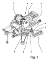
- Fig. 1 shows the overall structure of the sawing device according to the invention.
- the sawing device has a saw table 1, which in this case represents the base frame and a workpiece support surface 2. Arranged on the saw table 1 and mechanically coupled to the saw unit 3. Next is on the saw table 1 a substantially over the width of the saw table 1 extending stop 4 provided.
- the saw unit 3 has a rotatable about a rotation axis 5 Saw blade 6, which is driven by an electric motor 7.
- the saw unit 3 is in the present case extending parallel to the axis of rotation 5 of the saw blade 6 Swivel axis 8 swiveling. This is the design the sawing device as a chop saw.
- a workpiece is brought into contact with the stop 4 for machining, so that the workpiece has a clear alignment with respect to the saw blade 6.
- the stop 4 is connected by a fastening device 9 with the saw table. 1 releasably connected.
- the fastening device 9 is in the embodiment 1 realized as a screw, wherein the screw connection stop side has a slot. This slot has just enough game on that a fine positioning of the stopper 4 is possible.
- an adjusting device 10 is provided, which is configured separately from the fastening device 9.
- the special Advantage of this separate embodiment of fastening device 9 and Adjusting device 10 is that the powerful operation of the fastening device 9, the adjustment of the adjusting device 10 is not affected.
- the adjusting device 10 is arranged on the stop 4. But it can also be provided that the adjusting device 10 on Saw table 1 is provided, then, however, must be accepted that only a single adjustment of the adjusting device 10 for all substitutes Stops 4 is possible.
- the adjusting device 10 at least one adjusting screw 11, which in a stop 4 arranged threaded hole is screwed.
- Fig. 2 shows how the in the drawing right end of the adjusting screw 11 in contact with the saw table. 1 comes so that when mounted stop 4, the fine positioning of the stop 4 in the plane of the workpiece support surface 2 is possible.
- the adjusting screw 11 has a supporting function, so that forces on the adjusting screw 11 are transmitted or that the adjusting screw 11 only in such a way comes in contact with the saw table 1 that they are at fixed stop 4 substantially is free from forces.
- Fig. 3 shows the stop 4 of the sawing device according to the invention in perspective View.
- the adjustment device 10 here are two screws 11 are provided, which are each arranged on one end side of the stopper 4 (in Fig. 3, only the threaded holes can be seen).
- this two-sided Arrangement of the adjusting screws 11 is an optimal fine positioning given over the entire length of the attack 4.
- only one adjusting screw 11 is provided is, which is preferably arranged on one of the two end sides of the stopper 4 is.
- the adjusting screw 11 is designed to be self-locking, or that the adjusting screw 11 provided with a corresponding lock nut. Especially against the background, that the adjustment of the adjusting device 10 during disassembly and subsequent installation of the stop 4 is to be maintained, this is special advantageous.
- the stop 4 extends substantially over the width of the Saw Table 1. Basically, it should be noted that according to the invention also any Further dimensions and geometric configurations of the stop 4 possible are.
- clamp connections such as For example, an eccentric clamping device, are here for a trouble Disassembly and assembly provided.
- the stop 4 of the sawing device according to the invention can also be used as a component be provided a Schmiege.
- the Schmiege has one Schmiegekinematik on, with the two stops 4 are detachably connected.
- the Schmiegekinematik allows pivoting of the stops 4 such that the bisecting line in the space between the stops 4 always constant remains.
- an adjusting device 10 is provided, the above Preferences are now transferred to the Schmiege.
- a sawing device in question with a stop 4 which assigned a unique position on the saw table 1 is, in addition, a bend with a kinking kinematics and two strokes has, with the Schmiege associated attacks with the Schmiegekinematik are detachably connectable. It is envisaged that the stationary stop 4 and the Schmiege associated attacks depending on the application be used alternately.
Abstract
Description
Die Erfindung betrifft eine Sägevorrichtung gemäß dem Oberbegriff des Anspruchs
1.The invention relates to a sawing device according to the preamble of the
Sägevorrichtungen der in Rede stehenden Art weisen einen Sägetisch auf, der in der Regel stabil ausgestaltet ist und das Grundgestell der Sägevorrichtung bildet (DE 40 10 456 C2). Der Sägetisch weist üblicherweise eine Werkstückauflagefläche auf, auf der das zu bearbeitende Werkstück aufliegt.Sawing devices of the type in question have a saw table, which in the rule is designed to be stable and forms the base frame of the sawing device (DE 40 10 456 C2). The saw table usually has a workpiece support surface on which the workpiece to be machined rests.
Den meisten bekannten Ausführungsvarianten einer Sägevorrichtung ist gemeinsam, daß ein zu bearbeitendes Werkstück an einem Anschlag, der über eine Befestigungsvorrichtung mit dem Sägetisch verbunden ist, in Anlage kommt. Je nach Ausgestaltung der Sägevorrichtung sind auch mehrere Anschläge vorgesehen, die dann die Ausrichtung des Werkstücks gemeinsam gewährleisten.Most known variants of a sawing device are common, that a workpiece to be machined on a stop, via a fastening device connected to the saw table, comes into contact. ever after design of the sawing device, several stops are provided, which then ensure the alignment of the workpiece together.
Die Maßgenauigkeit des Anschlags selbst sowie die Lage des Anschlags bestimmen wesentlich die Sägegenauigkeit. Aus diesem Grund wird dort, wo es auf Genauigkeit ankommt, eine Möglichkeit zur Feinpositionierung des Anschlags vorgesehen, um die entstehenden Ungenauigkeiten ausgleichen zu können.The dimensional accuracy of the stop itself and the position of the stop significantly determine the sawing accuracy. That's why it gets where it is accuracy is important, a possibility for fine positioning of the stop provided to compensate for the resulting inaccuracies can.
Für eine derartige Feinpositionierung des Anschlags ist bei der Sägevorrichtung, von der die Erfindung ausgeht, der Anschlag verschiebbar gestaltet, so daß er im gelösten Zustand ggf. mit Hilfe einer Meßskala ausgerichtet werden kann (US 2,372,699 A). Nach dem Ausrichten wird der Anschlag dann durch Anziehen von Schraubverbindungen, die durch Langlöcher hindurchgreifen, auf dem Sägetisch fixiert.For such a fine positioning of the stop is in the sawing device, from the invention proceeds, designed the stop displaceable, so that he in dissolved state can be aligned if necessary by means of a measuring scale (US 2,372,699 A). After alignment, the stop is then tightened screw connections passing through slots on the saw table fixed.
Je nach Werkstück und je nach Sägeauftrag sind ggf. unterschiedliche Anschläge erforderlich. Die Anschläge können dabei in ihren Abmessungen, ihrer Form oder in ihrer konstruktiven Ausgestaltung voneinander abweichen. Um wenigstens den Aufwand für den Austausch der Anschläge gering zu halten, weist eine weitere bekannte Sägevorrichtung austauschbare Anschläge auf, die mit Befestigungsklammern auf die eigentlichen Anschläge, die am Sägetisch fixiert sind, aufsteckbar sind (DE 90 03 773 U 1).Depending on the workpiece and the sawing job, different stops may be necessary required. The attacks can be in their dimensions, their shape or differ in their structural design. At least the effort for the replacement of the attacks to keep low, has a other known sawing device exchangeable stops on, which with mounting brackets on the actual stops, which are fixed on the saw table, can be plugged (DE 90 03 773 U 1).
Im Ergebnis besteht ein Widerspruch zwischen der Flexibilität des Anschlags und dessen Genauigkeit. Mit der Austauschbarkeit der Anschläge ist die Feinpositionierung des Anschlags bei jedem Wechsel mit beträchtlichem Aufwand verbunden oder entfällt eben ganz.As a result, there is a contradiction between the flexibility of the attack and its accuracy. With the interchangeability of the stops is the fine positioning of attack with every change associated with considerable effort or completely eliminated.
Bei einer weiteren Sägevorrichtung, die speziell für die Durchführung von Gehrungsschnitten vorgesehen ist, ist der Anschlag am Sägetisch nur in einer festgelegten Position montierbar (US 5,816,129 A). Der Anschlag weist gegenüber einem Anschlaggrundkörper verschiebbare und schwenkbare Anschlagschienen auf.In another sawing device, especially for the implementation of miter cuts is provided, the stop on the saw table is only in a fixed Position mountable (US 5,816,129 A). The stop faces one Stop body slidable and swiveling stop rails on.
Der Erfindung liegt das Problem zugrunde, die bekannte Sägevorrichtung derart auszugestalten und weiterzubilden, daß die Austauschbarkeit der Anschläge bei konstanter Fertigungsgenauigkeit ohne erheblichen Arbeitsaufwand gegeben ist.The invention is based on the problem, the known sawing device such to design and develop that the interchangeability of the attacks in Constant manufacturing accuracy is given without considerable effort.
Die vorliegende Problemstellung wird durch eine Sägevorrichtung mit den
Merkmalen des Oberbegriffs von Anspruch 1 durch die Merkmale des kennzeichnenden
Teils von Anspruch 1 gelöst.The present problem is solved by a sawing device with the
Features of the preamble of
Wesentlich ist, daß eine einstellbare Justiervorrichtung zur Feinpositionierung des Anschlags am Sägetisch vorgesehen ist, die ihre Einstellung bei der Demontage und der Montage des Anschlags beibehält. Eine derartig ausgestaltete Justiervorrichtung hat den Vorteil, daß bei der Demontage und anschließenden Montage, oder aber beim Wechsel des Anschlags keine erneute Feinpositionierung erforderlich ist. Durch die Anordnung der Justiervorrichtung am Anschlag selbst wird erreicht, daß die zum jeweiligen Anschlag gehörige Einstellung der Justiervorrichtung bei der Demontage des Anschlags "mitgenommen" wird.It is essential that an adjustable adjusting device for fine positioning the stop is provided on the saw table, their setting during disassembly and the mounting of the stop retains. Such an adjusting device configured has the advantage that during disassembly and subsequent Mounting, or when changing the stop no re-fine positioning is required. By the arrangement of the adjusting device on the stop Even it is achieved that the belonging to the respective stop setting the Adjustment device when removing the stop "taken" is.
In besonders bevorzugter Ausgestaltung ist die Justiervorrichtung getrennt von einer Befestigungsvorrichtung des Anschlags am Anschlag selbst angeordnet. Mit der Trennung zwischen Justiervorrichtung und Befestigungsvorrichtung wird erreicht, daß bei der Befestigung aufzuwendende Kräfte sich nicht auf die Einstillung der Justiervorrichtung auswirken.In a particularly preferred embodiment, the adjusting device is separated from a fastening device of the stop on the stop itself arranged. With the separation between the adjusting device and fastening device is achieved that expended in the attachment forces are not on the Einstillung affect the adjusting device.
Es gibt eine Vielzahl von Möglichkeiten, die Lehre der Erfindung auszugestalten und weiterzubilden. Dazu darf auf die Unteransprüche verwiesen werden.There are a variety of ways to design the teachings of the invention and further education. For this purpose, reference may be made to the dependent claims.
Im folgenden wird die Erfindung anhand einer lediglich ein Ausführungsbeispiel darstellenden Zeichnung näher erläutert. In der Zeichnung zeigt
- Fig. 1
- eine Gesamtansicht der erfindungsgemäßen Sägevorrichtung,
- Fig. 2
- eine Seitenansicht der Sägevorrichtung aus Fig. 1,
- Fig. 3
- eine perspektivische Ansicht des Anschlags der Sägevorrichtung aus Fig. 1
- Fig. 1
- an overall view of the sawing device according to the invention,
- Fig. 2
- a side view of the sawing device of Fig. 1,
- Fig. 3
- a perspective view of the stop of the sawing device of FIG. 1st
Fig. 1 zeigt den Gesamtaufbau der erfindungsgemäßen Sägevorrichtung. Die Sägevorrichtung
weist einen Sägetisch 1 auf, der vorliegend das Grundgestell darstellt
und eine Werkstückauflagefläche 2 aufweist. Am Sägetisch 1 angeordnet
und mit diesem mechanisch gekoppelt ist das Sägeaggregat 3. Weiter ist am Sägetisch
1 ein im wesentlichen über die Breite des Sägetisches 1 verlaufender Anschlag
4 vorgesehen. Das Sägeaggregat 3 weist ein um eine Drehachse 5 drehbares
Sägeblatt 6 auf, das durch einen Elektromotor 7 angetrieben wird. Das Sägeaggregat
3 ist vorliegend um eine parallel zur Drehachse 5 des Sägeblatts 6 verlaufende
Schwenkachse 8 schwenkbar. Es handelt sich hierbei um die Ausgestaltung
der Sägevorrichtung als Kappsäge.Fig. 1 shows the overall structure of the sawing device according to the invention. The sawing device
has a saw table 1, which in this case represents the base frame
and a
Ein Werkstück wird zur Bearbeitung in Anlage an dem Anschlag 4 gebracht, so
daß das Werkstück eine eindeutige Ausrichtung gegenüber dem Sägeblatt 6 aufweist.A workpiece is brought into contact with the
Der Anschlag 4 ist durch eine Befestigungsvorrichtung 9 mit dem Sägetisch 1
lösbar verbunden. Die Befestigungsvorrichtung 9 ist im Ausführungsbeispiel
nach Fig. 1 als Schraubverbindung realisiert, wobei die Schraubverbindung anschlagseitig
ein Langloch aufweist. Dieses Langloch weist gerade soviel Spiel
auf, daß eine Feinpositionierung des Anschlags 4 möglich ist.The
Zur Durchführung der Feinpositionierung ist eine Justiervorrichtung 10 vorgesehen,
die getrennt von der Befestigungsvorrichtung 9 ausgestaltet ist. Der besondere
Vorteil dieser getrennten Ausgestaltung von Befestigungsvorrichtung 9 und
Justiervorrichtung 10 besteht darin, daß das kraftaufwendige Betätigen der Befestigungsvorrichtung
9 die Einstellung der Justiervorrichtung 10 nicht beeinflußt.
In bevorzugter Ausgestaltung ist die Justiervorrichtung 10 am Anschlag 4 angeordnet.
Es kann aber auch vorgesehen werden, daß die Justiervorrichtung 10 am
Sägetisch 1 vorgesehen ist, dann allerdings muß in Kauf genommen werden, daß
nur eine einzige Einstellung der Justiervorrichtung 10 für alle eingewechselten
Anschläge 4 möglich ist.To carry out the fine positioning, an adjusting
In besonders bevorzugter Ausgestaltung der Lehre der Erfindung weist die Justiervorrichtung
10 mindestens eine Einstellschraube 11 auf, die in eine im Anschlag
4 angeordnete Gewindebohrung eingeschraubt ist. Fig. 2 zeigt, wie das in
der Zeichnung rechte Ende der Einstellschraube 11 in Anlage an dem Sägetisch 1
kommt, so daß bei montiertem Anschlag 4 die Feinpositionierung des Anschlags
4 in der Ebene der Werkstückauflagefläche 2 möglich ist.In a particularly preferred embodiment of the teaching of the invention, the adjusting
Je nach Befestigungsvorrichtung 9 kann es vorgesehen sein, daß der Einstellschraube
11 eine tragende Funktion zukommt, daß also Kräfte über die Einstellschraube
11 übertragen werden oder daß die Einstellschraube 11 lediglich derart
in Anlage an dem Sägetisch 1 kommt, daß sie bei befestigtem Anschlag 4 im wesentlichen
frei von Kräften ist.Depending on the
Fig. 3 zeigt den Anschlag 4 der erfindungsgemäßen Sägevorrichtung in perspektivischer
Ansicht. Für die Justiervorrichtung 10 sind hier zwei Einstellschrauben
11 vorgesehen, die jeweils an einer Endseite des Anschlags 4 angeordnet sind (in
Fig. 3 sind lediglich die Gewindebohrungen zu erkennen). Mit dieser beidseitigen
Anordnung der Einstellschrauben 11 ist eine optimale Feinpositionierung
über die gesamte Länge des Anschlags 4 gegeben. In einfacher Ausgestaltung
kann es aber auch vorgesehen sein, daß nur eine Einstellschraube 11 vorgesehen
ist, die vorzugsweise an einem der beiden Endseiten des Anschlags 4 angeordnet
ist.Fig. 3 shows the
Weiter ist es in besonders bevorzugter Ausgestaltung vorgesehen, daß die Einstellschraube
11 selbsthemmend ausgestaltet ist, oder daß die Einstellschraube 11
mit einer entsprechenden Kontermutter versehen ist. Insbesondere vor dem Hintergrund,
daß die Einstellung der Justiervorrichtung 10 bei der Demontage und
anschließenden Montage des Anschlags 4 beibehalten werden soll, ist dies besonders
vorteilhaft.Further, it is provided in a particularly preferred embodiment, that the adjusting
Wie bereits erläutert wurde, ist im Ausführungsbeispiel nach Fig. 1 eine Feinpositionierung
des Anschlags 4 im wesentlichen in der Ebene der Werkstückauflagefläche
2 des Sägetischs 1 durchführbar. Es ist aber auch denkbar, daß je nach
Ausgestaltung der Justiervorrichtung 10 und entsprechender Anordnung der Einstellschraube
11 eine Feinpositionierung in anderen Vorzugsrichtungen realisierbar
ist.As already explained, in the embodiment of FIG. 1 is a fine positioning
the
In besonderer Ausgestaltung und auch im Ausführungsbeispiel nach Fig. 1 so
vorgesehen, erstreckt sich der Anschlag 4 im wesentlichen über die Breite des
Sägetischs 1. Grundsätzlich ist zu bemerken, daß erfindungsgemäß auch beliebige
weitere Abmessungen und geometrische Ausgestaltungen des Anschlags 4
möglich sind.In a special embodiment and also in the embodiment of FIG. 1 so
provided, the
Auch die Ausgestaltung der Befestigungsvorrichtung 9 ist nicht auf die oben genannte
Schraubverbindung beschränkt. Insbesondere Klemmverbindungen, wie
beispielsweise eine Exzenter-Spanneinrichtung, sind hier für eine problemlose
Demontage und Montage vorgesehen.The design of the
Der Anschlag 4 der erfindungsgemäßen Sägevorrichtung kann aber auch als Bestandteil
einer Schmiege vorgesehen sein. Die Schmiege weist dabei eine
Schmiegekinematik auf, mit der zwei Anschläge 4 lösbar verbunden sind. Die
Schmiegekinematik ermöglicht ein Verschwenken der Anschläge 4 derart, daß
die Winkelhalbierende im Raum zwischen den Anschlägen 4 stets konstant
bleibt. Hier ist ebenfalls eine Justiervorrichtung 10 vorgesehen, deren oben genannten
Vorzüge nun auf die Schmiege übertragen werden. The
Des weiteren kann vorgesehen sein, daß eine in Rede stehende Sägevorrichtung
mit einem Anschlag 4, dem eine eindeutige Position am Sägetisch 1 zugeordnet
ist, zusätzlich eine Schmiege mit einer Schmiegekinematik und zwei Anschlägen
aufweist, wobei die der Schmiege zugeordneten Anschläge mit der Schmiegekinematik
lösbar verbindbar sind. Dabei ist es vorgesehen, daß der ortsfeste Anschlag
4 und die der Schmiege zugeordneten Anschläge je nach Anwendungsfall
abwechselnd genutzt werden.Furthermore, it can be provided that a sawing device in question
with a
Besonders vorteilhaft ist es, wenn eine Justiervorrichtung 10 zur Feinpositionierung
des ortsfesten Anschlags 4 und ggf. auch der der Schmiege zugeordneten
Anschläge vorgesehen ist. Dann erst läßt sich die gewünschte Flexibilität mit
gleichzeitig hoher Genauigkeit gewährleisten.It is particularly advantageous if an adjusting
Wesentlich ist, daß der Anschlag 4 als solcher für eine Sägevorrichtung der in
Rede stehenden Art eine einstellbare Justiervorrichtung 10 zur Feinpositionierung
des Anschlags 4 am Sägetisch 1 aufweist.It is essential that the
Claims (8)
- Sawing device comprising a saw table (1), a saw unit (3) arranged on the saw table (1), and at least one stop (4), the saw unit (3) having a saw blade (6) rotatable about a rotation axis (5), the saw unit (3) preferably being pivotable about a pivot axis (8) running parallel to the rotation axis (5) of the saw blade (6), it being possible for a workpiece which is to be machined to be brought to bear against the stop (4) for orientation relative to the saw blade (6), the stop (4) being releasably connected directly to the saw table (1) by a fastening device (9), characterized in that a settable adjusting device (10) is provided for the fine positioning of the stop (4) on the saw table (1), this adjusting device (10) being designed in such a way that its setting is retained when the stop (4) is removed from and fitted on the saw table (1), in that the adjusting device (10) has at least one setting screw (11) which is screwed into a tapped hole arranged in the stop (4), and in that, when the stop (4) is fitted, one end of the setting screw (11) comes to bear against the saw table (1).
- Sawing device according to Claim 1, characterized in that the adjusting device (10) is designed to be separate from the fastening device (9).
- Sawing device according to either of the preceding claims, characterized in that the stop (4), in the fitted state, is supported on the saw table (1) via the setting screw (11).
- Sawing device according to one of the preceding claims, characterized in that the adjusting device (10) has two setting screws (11) which are each arranged at an end side of the stop (4).
- Sawing device according to one of the preceding claims, characterized in that the setting screw (11) is designed to be self-locking or is provided with a lock nut.
- Sawing device according to one of the preceding claims, characterized in that the fine positioning of the stop (4) can be carried out essentially in the plane of a work-supporting surface (2) of the saw table (1) by the adjusting device (10).
- Sawing device according to one of the preceding claims, characterized in that the stop (4) extends essentially over the full width of the saw table (1).
- Sawing device according to one of the preceding claims, characterized in that the fastening device (9) has a screwed connection, the screw of the screwed connection preferably running through an elongated hole arranged in the stop (4), or in that the fastening device (9) has a clamping connection, preferably an eccentric clamping device.
Applications Claiming Priority (2)
| Application Number | Priority Date | Filing Date | Title |
|---|---|---|---|
| DE20203147U DE20203147U1 (en) | 2002-02-28 | 2002-02-28 | sawing |
| DE20203147U | 2002-02-28 |
Publications (3)
| Publication Number | Publication Date |
|---|---|
| EP1340603A2 EP1340603A2 (en) | 2003-09-03 |
| EP1340603A3 EP1340603A3 (en) | 2004-03-24 |
| EP1340603B1 true EP1340603B1 (en) | 2005-06-15 |
Family
ID=7968385
Family Applications (1)
| Application Number | Title | Priority Date | Filing Date |
|---|---|---|---|
| EP02028674A Expired - Lifetime EP1340603B1 (en) | 2002-02-28 | 2002-12-20 | Sawing device |
Country Status (4)
| Country | Link |
|---|---|
| EP (1) | EP1340603B1 (en) |
| AT (1) | ATE297840T1 (en) |
| DE (2) | DE20203147U1 (en) |
| DK (1) | DK1340603T3 (en) |
Families Citing this family (2)
| Publication number | Priority date | Publication date | Assignee | Title |
|---|---|---|---|---|
| DE102004004725B3 (en) * | 2004-01-29 | 2005-05-04 | Metabowerke Gmbh | Cut-off saw, mainly for wood, has holder outside cutting line of both planes passing through saw blade and workpiece resting surface |
| US20060236833A1 (en) * | 2005-04-25 | 2006-10-26 | Meredith Daryl S | Fence arrangement for a miter saw |
Family Cites Families (3)
| Publication number | Priority date | Publication date | Assignee | Title |
|---|---|---|---|---|
| US2372699A (en) * | 1941-07-18 | 1945-04-03 | Delta Mfg Co | Cutting machine |
| US5816129A (en) * | 1995-12-19 | 1998-10-06 | Singer; David K. | Miter fence for radial arm saw |
| DE19729552A1 (en) * | 1997-07-10 | 1999-01-14 | Reich Maschf Gmbh Karl | Stop device for miter saw |
-
2002
- 2002-02-28 DE DE20203147U patent/DE20203147U1/en not_active Expired - Lifetime
- 2002-12-20 DK DK02028674T patent/DK1340603T3/en active
- 2002-12-20 DE DE50203406T patent/DE50203406D1/en not_active Expired - Lifetime
- 2002-12-20 EP EP02028674A patent/EP1340603B1/en not_active Expired - Lifetime
- 2002-12-20 AT AT02028674T patent/ATE297840T1/en not_active IP Right Cessation
Also Published As
| Publication number | Publication date |
|---|---|
| DK1340603T3 (en) | 2005-08-29 |
| DE50203406D1 (en) | 2005-07-21 |
| DE20203147U1 (en) | 2002-06-06 |
| ATE297840T1 (en) | 2005-07-15 |
| EP1340603A2 (en) | 2003-09-03 |
| EP1340603A3 (en) | 2004-03-24 |
Similar Documents
| Publication | Publication Date | Title |
|---|---|---|
| DE2339873C2 (en) | Arrangement for setting and securing a block carrying a cutting tip in a groove-shaped receptacle in the tool body of a cutting tool | |
| EP2065673B1 (en) | Bevel | |
| WO1990002633A2 (en) | Clamping device | |
| DE2421954C2 (en) | Angle guide for stationary or mobile hand routers | |
| EP0716898A1 (en) | Saber saw with angularly adjustable guide plate | |
| AT391645B (en) | TEACHING DEVICE FOR FURNITURE PARTS | |
| EP1815939A1 (en) | Positioning means for a clamping unit with positioning plates and console sliding through grooves and T-nuts ; Clamping device with such positioning means | |
| EP1007461A1 (en) | Buckle folder machine with two or three folder pockets | |
| EP0306626B1 (en) | Adjusting device for the steering linkage of a wheel | |
| DE1453213C3 (en) | ||
| EP1340603B1 (en) | Sawing device | |
| EP1498224B1 (en) | Carrier head | |
| EP1466688A1 (en) | Circular saw | |
| DE202022002642U1 (en) | Variable profile clamping device for jigsaw tables | |
| EP0118077B1 (en) | Mitring stop | |
| DE3211460A1 (en) | CUTTING TOOL | |
| EP0292864A1 (en) | Wood-working machine | |
| CH619878A5 (en) | Boring tool with two individually adjustable tool noses | |
| EP1402985A2 (en) | Clamping device | |
| EP0058369A2 (en) | Feeding device for woodworking machine-tools | |
| WO1992003253A1 (en) | Clamping device for machine tools | |
| EP0325738A2 (en) | Clamping device | |
| DE2263634C3 (en) | Tool for simultaneous machining of the flanks of grooves | |
| EP0117505B1 (en) | Wood working machine | |
| EP0216051B1 (en) | Tool holder |
Legal Events
| Date | Code | Title | Description |
|---|---|---|---|
| PUAI | Public reference made under article 153(3) epc to a published international application that has entered the european phase |
Free format text: ORIGINAL CODE: 0009012 |
|
| AK | Designated contracting states |
Kind code of ref document: A2 Designated state(s): AT BE BG CH CY CZ DE DK EE ES FI FR GB GR IE IT LI LU MC NL PT SE SI SK TR |
|
| AX | Request for extension of the european patent |
Extension state: AL LT LV MK RO |
|
| PUAL | Search report despatched |
Free format text: ORIGINAL CODE: 0009013 |
|
| AK | Designated contracting states |
Kind code of ref document: A3 Designated state(s): AT BE BG CH CY CZ DE DK EE ES FI FR GB GR IE IT LI LU MC NL PT SE SI SK TR |
|
| AX | Request for extension of the european patent |
Extension state: AL LT LV MK RO |
|
| RIC1 | Information provided on ipc code assigned before grant |
Ipc: 7B 27B 27/04 B Ipc: 7B 23D 45/04 B Ipc: 7B 27B 27/10 A |
|
| 17P | Request for examination filed |
Effective date: 20040420 |
|
| 17Q | First examination report despatched |
Effective date: 20040728 |
|
| GRAP | Despatch of communication of intention to grant a patent |
Free format text: ORIGINAL CODE: EPIDOSNIGR1 |
|
| AKX | Designation fees paid |
Designated state(s): AT BE BG CH CY CZ DE DK EE ES FI FR GB GR IE IT LI LU MC NL PT SE SI SK TR |
|
| GRAS | Grant fee paid |
Free format text: ORIGINAL CODE: EPIDOSNIGR3 |
|
| GRAA | (expected) grant |
Free format text: ORIGINAL CODE: 0009210 |
|
| AK | Designated contracting states |
Kind code of ref document: B1 Designated state(s): AT BE BG CH CY CZ DE DK EE ES FI FR GB GR IE IT LI LU MC NL PT SE SI SK TR |
|
| PG25 | Lapsed in a contracting state [announced via postgrant information from national office to epo] |
Ref country code: TR Free format text: LAPSE BECAUSE OF FAILURE TO SUBMIT A TRANSLATION OF THE DESCRIPTION OR TO PAY THE FEE WITHIN THE PRESCRIBED TIME-LIMIT Effective date: 20050615 Ref country code: FI Free format text: LAPSE BECAUSE OF FAILURE TO SUBMIT A TRANSLATION OF THE DESCRIPTION OR TO PAY THE FEE WITHIN THE PRESCRIBED TIME-LIMIT Effective date: 20050615 Ref country code: SI Free format text: LAPSE BECAUSE OF FAILURE TO SUBMIT A TRANSLATION OF THE DESCRIPTION OR TO PAY THE FEE WITHIN THE PRESCRIBED TIME-LIMIT Effective date: 20050615 Ref country code: IE Free format text: LAPSE BECAUSE OF FAILURE TO SUBMIT A TRANSLATION OF THE DESCRIPTION OR TO PAY THE FEE WITHIN THE PRESCRIBED TIME-LIMIT Effective date: 20050615 Ref country code: CZ Free format text: LAPSE BECAUSE OF FAILURE TO SUBMIT A TRANSLATION OF THE DESCRIPTION OR TO PAY THE FEE WITHIN THE PRESCRIBED TIME-LIMIT Effective date: 20050615 Ref country code: NL Free format text: LAPSE BECAUSE OF FAILURE TO SUBMIT A TRANSLATION OF THE DESCRIPTION OR TO PAY THE FEE WITHIN THE PRESCRIBED TIME-LIMIT Effective date: 20050615 Ref country code: SK Free format text: LAPSE BECAUSE OF FAILURE TO SUBMIT A TRANSLATION OF THE DESCRIPTION OR TO PAY THE FEE WITHIN THE PRESCRIBED TIME-LIMIT Effective date: 20050615 Ref country code: EE Free format text: LAPSE BECAUSE OF FAILURE TO SUBMIT A TRANSLATION OF THE DESCRIPTION OR TO PAY THE FEE WITHIN THE PRESCRIBED TIME-LIMIT Effective date: 20050615 |
|
| REG | Reference to a national code |
Ref country code: GB Ref legal event code: FG4D Free format text: NOT ENGLISH Ref country code: CH Ref legal event code: EP Ref country code: CH Ref legal event code: NV Representative=s name: KELLER & PARTNER PATENTANWAELTE AG |
|
| REF | Corresponds to: |
Ref document number: 50203406 Country of ref document: DE Date of ref document: 20050721 Kind code of ref document: P |
|
| REG | Reference to a national code |
Ref country code: IE Ref legal event code: FG4D Free format text: LANGUAGE OF EP DOCUMENT: GERMAN |
|
| REG | Reference to a national code |
Ref country code: DK Ref legal event code: T3 |
|
| PG25 | Lapsed in a contracting state [announced via postgrant information from national office to epo] |
Ref country code: SE Free format text: LAPSE BECAUSE OF FAILURE TO SUBMIT A TRANSLATION OF THE DESCRIPTION OR TO PAY THE FEE WITHIN THE PRESCRIBED TIME-LIMIT Effective date: 20050915 Ref country code: BG Free format text: LAPSE BECAUSE OF FAILURE TO SUBMIT A TRANSLATION OF THE DESCRIPTION OR TO PAY THE FEE WITHIN THE PRESCRIBED TIME-LIMIT Effective date: 20050915 Ref country code: GR Free format text: LAPSE BECAUSE OF FAILURE TO SUBMIT A TRANSLATION OF THE DESCRIPTION OR TO PAY THE FEE WITHIN THE PRESCRIBED TIME-LIMIT Effective date: 20050915 |
|
| PG25 | Lapsed in a contracting state [announced via postgrant information from national office to epo] |
Ref country code: ES Free format text: LAPSE BECAUSE OF FAILURE TO SUBMIT A TRANSLATION OF THE DESCRIPTION OR TO PAY THE FEE WITHIN THE PRESCRIBED TIME-LIMIT Effective date: 20050926 |
|
| GBT | Gb: translation of ep patent filed (gb section 77(6)(a)/1977) |
Effective date: 20050908 |
|
| PG25 | Lapsed in a contracting state [announced via postgrant information from national office to epo] |
Ref country code: PT Free format text: LAPSE BECAUSE OF FAILURE TO SUBMIT A TRANSLATION OF THE DESCRIPTION OR TO PAY THE FEE WITHIN THE PRESCRIBED TIME-LIMIT Effective date: 20051124 |
|
| NLV1 | Nl: lapsed or annulled due to failure to fulfill the requirements of art. 29p and 29m of the patents act | ||
| PG25 | Lapsed in a contracting state [announced via postgrant information from national office to epo] |
Ref country code: AT Free format text: LAPSE BECAUSE OF NON-PAYMENT OF DUE FEES Effective date: 20051220 Ref country code: CY Free format text: LAPSE BECAUSE OF FAILURE TO SUBMIT A TRANSLATION OF THE DESCRIPTION OR TO PAY THE FEE WITHIN THE PRESCRIBED TIME-LIMIT Effective date: 20051220 |
|
| PG25 | Lapsed in a contracting state [announced via postgrant information from national office to epo] |
Ref country code: MC Free format text: LAPSE BECAUSE OF NON-PAYMENT OF DUE FEES Effective date: 20051231 Ref country code: LU Free format text: LAPSE BECAUSE OF NON-PAYMENT OF DUE FEES Effective date: 20051231 |
|
| REG | Reference to a national code |
Ref country code: IE Ref legal event code: FD4D |
|
| ET | Fr: translation filed | ||
| PLBE | No opposition filed within time limit |
Free format text: ORIGINAL CODE: 0009261 |
|
| STAA | Information on the status of an ep patent application or granted ep patent |
Free format text: STATUS: NO OPPOSITION FILED WITHIN TIME LIMIT |
|
| 26N | No opposition filed |
Effective date: 20060316 |
|
| PGFP | Annual fee paid to national office [announced via postgrant information from national office to epo] |
Ref country code: CH Payment date: 20091224 Year of fee payment: 8 Ref country code: DK Payment date: 20091214 Year of fee payment: 8 |
|
| PGFP | Annual fee paid to national office [announced via postgrant information from national office to epo] |
Ref country code: IT Payment date: 20091223 Year of fee payment: 8 |
|
| PGFP | Annual fee paid to national office [announced via postgrant information from national office to epo] |
Ref country code: BE Payment date: 20100212 Year of fee payment: 8 |
|
| BERE | Be: lapsed |
Owner name: *METABOWERKE G.M.B.H. Effective date: 20101231 |
|
| REG | Reference to a national code |
Ref country code: CH Ref legal event code: PL |
|
| REG | Reference to a national code |
Ref country code: DK Ref legal event code: EBP |
|
| PG25 | Lapsed in a contracting state [announced via postgrant information from national office to epo] |
Ref country code: BE Free format text: LAPSE BECAUSE OF NON-PAYMENT OF DUE FEES Effective date: 20101231 |
|
| PG25 | Lapsed in a contracting state [announced via postgrant information from national office to epo] |
Ref country code: CH Free format text: LAPSE BECAUSE OF NON-PAYMENT OF DUE FEES Effective date: 20101231 Ref country code: LI Free format text: LAPSE BECAUSE OF NON-PAYMENT OF DUE FEES Effective date: 20101231 |
|
| PG25 | Lapsed in a contracting state [announced via postgrant information from national office to epo] |
Ref country code: IT Free format text: LAPSE BECAUSE OF NON-PAYMENT OF DUE FEES Effective date: 20101220 |
|
| PGFP | Annual fee paid to national office [announced via postgrant information from national office to epo] |
Ref country code: GB Payment date: 20121218 Year of fee payment: 11 |
|
| PGFP | Annual fee paid to national office [announced via postgrant information from national office to epo] |
Ref country code: FR Payment date: 20130123 Year of fee payment: 11 Ref country code: DE Payment date: 20130220 Year of fee payment: 11 |
|
| REG | Reference to a national code |
Ref country code: DE Ref legal event code: R119 Ref document number: 50203406 Country of ref document: DE |
|
| GBPC | Gb: european patent ceased through non-payment of renewal fee |
Effective date: 20131220 |
|
| REG | Reference to a national code |
Ref country code: FR Ref legal event code: ST Effective date: 20140829 |
|
| REG | Reference to a national code |
Ref country code: DE Ref legal event code: R119 Ref document number: 50203406 Country of ref document: DE Effective date: 20140701 |
|
| PG25 | Lapsed in a contracting state [announced via postgrant information from national office to epo] |
Ref country code: DE Free format text: LAPSE BECAUSE OF NON-PAYMENT OF DUE FEES Effective date: 20140701 |
|
| PG25 | Lapsed in a contracting state [announced via postgrant information from national office to epo] |
Ref country code: GB Free format text: LAPSE BECAUSE OF NON-PAYMENT OF DUE FEES Effective date: 20131220 Ref country code: FR Free format text: LAPSE BECAUSE OF NON-PAYMENT OF DUE FEES Effective date: 20131231 |