EP1340579A2 - Thermische Spritzeinrichtung - Google Patents
Thermische Spritzeinrichtung Download PDFInfo
- Publication number
- EP1340579A2 EP1340579A2 EP03290477A EP03290477A EP1340579A2 EP 1340579 A2 EP1340579 A2 EP 1340579A2 EP 03290477 A EP03290477 A EP 03290477A EP 03290477 A EP03290477 A EP 03290477A EP 1340579 A2 EP1340579 A2 EP 1340579A2
- Authority
- EP
- European Patent Office
- Prior art keywords
- jet
- torch
- projection
- computer
- instrument according
- Prior art date
- Legal status (The legal status is an assumption and is not a legal conclusion. Google has not performed a legal analysis and makes no representation as to the accuracy of the status listed.)
- Granted
Links
Images

Classifications
-
- B—PERFORMING OPERATIONS; TRANSPORTING
- B23—MACHINE TOOLS; METAL-WORKING NOT OTHERWISE PROVIDED FOR
- B23K—SOLDERING OR UNSOLDERING; WELDING; CLADDING OR PLATING BY SOLDERING OR WELDING; CUTTING BY APPLYING HEAT LOCALLY, e.g. FLAME CUTTING; WORKING BY LASER BEAM
- B23K10/00—Welding or cutting by means of a plasma
- B23K10/006—Control circuits therefor
Definitions
- the invention relates to the coating of surfaces by thermal spraying of materials molten using a thermal spray torch, hereinafter called a torch, and more particularly to a thermal spraying instrument comprising a device for control and piloting of thermal spraying.
- Thermal spraying is a well known process for coating a solid surface with a material having a high melting point. It consists in melting the material in a flow of hot gas at high speed directed on the surface, the gas flow causing the pulverization of the material in fine molten droplets and the entrainment of the droplets towards the surface, the droplets still at the molten state crashing onto the surface, the droplets adhering to this surface and solidifying on contact.
- the flow of gas charged with molten droplets is called a jet.
- the coating is obtained by successive passes by moving the jet relative to the surface.
- Thermal spraying can be used for different purposes: decoration, thermal barrier, protection against oxidation or chemical corrosion, reloading of material, increase in the mechanical characteristics of the surface, in particular its resistance to abrasion, etc.
- the projected material can be a pure metal such as molybdenum or titanium, a metallic alloy such as NiCr, NiAl, NiCrAIY, a ceramic such as Cr2O3 or ZrO2, a carbide such as WC or Cr3C2, or a cermet such Cr3C2 / NiCr.
- the so-called "flame" thermal projection consists in producing a flame by the combustion of high calorific gases such as acetylene and oxygen, the rise of temperature producing a high speed gas stream into which the material to be sprayed in the form of powder or wire. Matter melts on contact with flame, pulverizes into fine droplets in the flow of hot combustion gases and is driven by this flow to form the jet.
- high calorific gases such as acetylene and oxygen
- the thermal projection called "by arc-wire” consists in producing an electric arc between two son of the material to be projected and to pass a flow of neutral gas, such as argon Ar, to high speed on the electric arc.
- the material of the wires liquefies in the presence of the arc electric, is sprayed into fine droplets in the flow of hot combustion gases and is driven by this flow to form the jet.
- the so-called “plasma arc” thermal projection consists in producing heat by maintaining an electric arc in a stream of plasma gas, the formation of plasma causing a sharp rise in the temperature of the gas, and to inject into this flow the powder material to be sprayed, this powder being fluidized and transported by a gas neutral says "carrier”.
- the assembly consisting of the plasma gas, the carrier gas and the molten material in fine droplets in contact with the plasma gas forms the jet.
- the jet at the exit of the torch has the shape of a diverging cone. Because of the high temperatures implemented, a torch gradually degrades in operation, this degradation causing drifts in its functioning as well as deformations and deviations of the jet. In some types of plasma arc torch, powder injection is done at the exit of the torch transverse to the gas flow plasmagen, which causes a normal deflection of the jet,
- the torch is usually small in order to be conveniently moved in front of the surface to be covered.
- This torch is connected to a control cabinet which supplies it with electric current and the various ingredients necessary for its operation. Through ingredients means the gases and materials described above.
- the quality criteria for a thermal spray deposit are usually its hardness, its adhesion to the coated surface, its porosity, the absence of cracks, the rate unfounded and, in the case of metallic materials, its oxide level.
- rate means the proportion of the material constituting the deposit that has not passed by the molten state.
- the quality of the deposit and the yield of the deposit operation obviously depend on the material used but also the setting and type of torch.
- the material flow by example in grams per minute, is obviously a parameter common to all torches.
- the gas flow rates must also be adjusted fuel and oxidizer expressed for example in liters per minute.
- the arc intensity in amps and the gas flow must also be adjusted.
- a constant quality of deposit is difficult to ensure because the torch and its supply of ingredients are subject to uncertainties and drifts over time which modify obviously this quality.
- During coating operations it is also necessary periodically carry out checks on samples and modify the adjustments, or even change the torch if necessary. Indeed, a torch degrades gradually in operation, especially in its hot parts such as the nozzle ejection, these degradations being able to derive the characteristics of the torch and deform or move the jet.
- These checks must be frequent in order to be able to detect sufficiently early the appearance of a drift and to be able to modify the torch settings, before the quality of the deposit has itself drifted outside acceptable limits.
- These controls and these adjustments obviously take time and reduce the productivity of installation.
- a first problem to solve is to verify that the torch is able to ensure a deposit whose characteristics are in accordance with what was planned, this verification that must necessarily be done in real time during a projection operation thermal, and also correct in real time the operation of this torch when drifts are noted.
- a third problem is to automatically stop the torch when it is no longer in use. able to function normally and therefore risks producing defective coatings.
- the computer also measures and processes the position P of the jet, P also constituting a projection characteristic, an order of priority being defined in the treatment of the projection characteristics, the treatment of the width L of the jet remaining the highest priority, the camera being capable of observing the jet with a resolution at least equal to 0.5 mm, P being, to within a constant value P 0 , the mean of the distribution of the luminance of the jet along a geometric line transverse to the jet.
- P is, to within a constant value P 0 , the mean of the distribution of the luminance of the jet along a geometric line transverse to the jet.
- the computer also measures and processes the maximum intensity I max of the jet, this measurement I max then also constituting a projection characteristic, the computer being able to process the projection characteristics with an order of priority, the processing of the width L of the jet being the highest priority, the processing of the maximum intensity I max of the jet arriving in priority second.
- the computer is able to process the projection characteristics with an order of priority, the processing of the width L of the jet being the highest priority, the processing of the maximum intensity I max of the jet arriving in priority second.
- the camera will advantageously be of the CCD type, the accumulation of charge in the pixels of the matrix having the effect of filtering the high-frequency vibrations of the jet and, as a result, improving the estimation of the characteristics of the jet, and consequently having better control thermal projection. Measurements can be made simply in the visible light spectrum.
- we will take a camera offering images of the jet with a resolution at least equal to 0.1mm in order to better master the characteristics of projection and by repercussion the characteristics of the deposits carried out.
- the camera, the pyrometer and the computer means used are widespread in the trade and inexpensive, which thus solves the second problem.
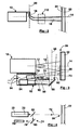
- the thermal projection instrument 10 comprises a thermal projection torch 12 with a geometric axis 14 projecting along this axis geometric 14 a jet 16 consisting of a flow of hot gas charged with droplets of the material to be projected in fusion: metal, metallic alloy, ceramic or cermet.
- Jet 16 is diverging and usually has the shape of a cone of revolution centered on the axis geometric 14.
- Sometimes a very bright flame 17 emerges from the torch 12 in the area of the top of the cone formed by the jet 16. In the case of plasma torches, this flame 17 can reach a temperature of 8000 ° K. Beyond this flame 17, the jet is also luminous but this luminosity does not come now basically just droplets of molten material.
- Jet 16 is normally centered on the geometric axis 14. Because of the high temperatures used in the torch 16 and despite the cooling devices integrated in these torches 16, the torches 16 degrade in particular by erosion during their operation, these degradations which can modify the characteristics of jet 16, deform jet 16 or do so deviate from the geometric axis 14.
- the torch 12 is of plasma arc type with transverse injection and includes an injector 18 with a perpendicular geometric axis 20 to the geometric axis of the torch 14, this injector 18 injecting into the jet 16 the material to spray powder using a so-called carrier gas, this injection taking place just at the outlet torch 12 in the area of the top of the cone formed by the jet 16, this injection takes place making transverse to jet 16 and causing deflection of jet 16 in the direction opposite the injector 18, the jet 16 then deviating normally from the geometric axis 14 .
- the droplets of molten material projected by the jet 16 arrive at high speed and are crushed on the surface of the part 22 to be covered, in order to form there by solidification and adhesion deposit 24 sought.
- This deposit 24 is normally constituted by layers successive, the torch 12 repeatedly sweeping the surface of the part 22. will reference 26 the surface of the part 22 exposed at a given time to the jet 16.
- the torch can be held by hand, for example for repairing engineering structures metal. It is most often used on an installation 40 preferably robotized ensuring the relative maintenance, positioning and movement of the torch 12 and of part 22 to be treated.
- the installation 40 will advantageously include a robot arm 42 supporting the torch 12 as well as a fixed or pivoting workpiece holder 44 and maintaining the piece 22 in front of the torch 12.
- the projection instrument 10 includes on-board sensors 52 attached to the torch 12 so as to follow it in its movements during thermal projection, these on-board sensors 52 thus remaining in a constant relative position relative to the torch 12.
- the on-board sensors 52 consist first of all of a CCD camera 54 capable of providing digital images of the jet 16 taken transversely or even perpendicular to this jet 16.
- the camera 54 is positioned to provide an image of the jet 16 beyond the flame 17, that is to say downstream of this flame 17, so that the image of the jet 16 is not veiled by the light of the flame 17.
- the reference 56 will be geometrical axis of shooting of the camera 54.
- the camera 54 is arranged on the side of the torch 12 and aims the jet 16 by means of a shooting mirror 58 placed at 45 ° in front of the camera 54, this shooting mirror 58 deviating at 90 ° the geometric axis of the CCD camera 56 and allowing this CCD camera 54 to see the jet 16.
- a shooting mirror 58 placed at 45 ° in front of the camera 54, this shooting mirror 58 deviating at 90 ° the geometric axis of the CCD camera 56 and allowing this CCD camera 54 to see the jet 16.
- the camera must have sufficient resolution to perceive details of 0.5mm on the jet 16. This resolution is indeed necessary to detect and measure a deviation of the 0.5mm jet. In the case of aeronautical applications, this resolution should even be at least equal to 0.1mm in order to control the characteristics of the deposit with a sufficient precision.
- the camera has a CCD (Charge Coupled) matrix Device) of 640 x 480 pixels with an exposure time ranging from 1/30 second to 1/2000 second to observe very different light intensity jets with precision sufficient and without saturation of the pixels of the matrix.
- CCD camera sensitivity can be limited to the visible spectrum. A black and white camera is sufficient but you can also use a color camera. Such a camera is commonly marketed at low cost. It suffices that it has sufficient resistance to the heat given off during of thermal projection.
- the camera 54 is positioned to see the jet 16 along a geometric axis 56 substantially orthogonal to the geometric axis 20 of the injector 18, this position allowing to better visualize the deflection of jet 16 caused by this mode injection, this position therefore making it possible to more effectively control the jet deflection 16.
- the on-board sensors 52 also consist of an optical pyrometer 70 with a geometric axis 72 and remotely measuring the thermal radiation emitted by a so-called “measuring" surface 73, the measuring surface 73 being small on the geometric axis 72
- the pyrometer 70 is directive and it is capable of being pointed on the part 22 as close as possible to the projection area 26 but without however interfering with this projection area 26, that is to say that the measurement area 73 is close to or even adjacent to the projection area 26 but does not interfere with this projection area 26.
- the pyrometer 70 has a narrow field and it is positioned so that the field comes as close as possible to the jet 16 on the part 22 without however interfering with this jet 16.
- the very bright jet 16 remains outside the field of the pyrometer and in particular of the measurement zone 73 so that the pyrometer 70 receives the thermal radiation that of the deposit 24 but not the light radiation of the jet 16 which would be likely to distort the measurement of the temperature of the deposit.
- it advantageously includes a laser sight 74 projecting a light spot on the measurement area 73.
- the measurement of thermal radiation is usually done in the infrared, that is to say in the band of electromagnetic radiation ranging from 0.8 ⁇ m to 14 ⁇ m. In the particular case of plasma arc torches, this measurement will advantageously be made in the 8 ⁇ m - 14 ⁇ m band in order to have a stable, precise and inexpensive measurement.
- FIG. 4 An example of a viewfinder 74 is illustrated in FIG. 4. The viewfinder 74 projected a narrow laser beam 78 in the geometric axis 72 of the pyrometer 70.
- the viewfinder comprises a laser diode 76 placed on the side of the pyrometer 70, the laser diode 76 emitting a laser beam 78 at the front of the pyrometer 70 parallel to its geometric axis 72, the laser beam 78 being brought back into the geometric axis of the pyrometer 72 by a conventional set of two mirrors 80 and 82, the second mirror 82 being semi-reflecting and positioned on the geometric axis of the pyrometer 72.
- the adjustment of the viewfinder does not depend on the distance between the pyrometer 70 and the surface of the part whose temperature must be measured. It will be noted that the pyrometer 70 gives an exact measurement of the temperature only for perfect black bodies.
- the on-board sensors 52 are arranged at inside a closed enclosure 90 which protects them against external agents, this enclosure 90, however, comprising openings 92 allowing the camera 54 to see the jet 16 and with the pyrometer 70 to see the surface of the part 22, this enclosure 90 comprising a pressurized air supply 94, this pressurized air exiting by the openings 92 and obstructing the penetration of dust and droplets in the enclosure during the operation of the torch 12, this dust and droplets being likely to be deposited on the sensors 52 and in particular to foul the optical components.
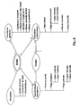
- the thermal projection instrument 10 also includes a computer 100 connected by connection 110 to the sensors on-board 52, that is to the camera 54 and to the pyrometer 70.
- computer 100 is capable of receiving digital images 112 in real time from camera 54 as well as temperature readings 114 from pyrometer 70.
- the computer 100 is also connected by connection 120 to the cabinet command 30.
- the computer 100 is capable of transmit the power parameters to the control cabinet 30 in real time.
- this connection 120 also, the computer is likely to receive in real time power supply parameters of the control cabinet 30, for example the voltage V of the arc in the case of a plasma torch.
- real time is meant the value information to be applied upon receipt or the current value of the information that will be transmitted.
- Computer 100 can be a commonly used microcomputer sold equipped with appropriate connection means to be able to be connected to connections 110 and 120 respectively to sensors 52 and to the control cabinet 30, this computer 100 must also have sufficient power to be able to perform treatments at the appropriate frequency.
- the computer 100 also includes a base 130 containing the information necessary for controlling and steering the thermal spraying.
- the information is grouped into models, each model providing the information required to manage a deposit operation by thermal spraying with a torch, a deposition composition and specified deposit characteristics.
- the maximum luminous intensity of the jet I max is the maximum luminance of the jet 16, this maximum luminance of the jet usually being in the center of the jet 16 seen laterally from the outside and downstream of any flame 17 coming out of the torch 12.
- Luminance is a physical quantity expressable in watts per square meter and per steradian (w / m 2 / sr).
- the maximum light level of the pixels of the dot image 112 given by the matrix of the CCD camera 54 will be taken. This light level is common to known image standards such as bitmap, GIF, PSD, etc. It is usually coded on eight bits and consequently ranges from zero to 255.
- the CCD camera 54 used provides color images, that is to say in red-green-blue additive tri-color, we can simply take, but this is not compulsory, the maximum light level of the color green, this green color being the closest to the behavior of a CCD camera in black and white.
- the position of the jet P is the position of the jet relative to the geometric axis 14 of the torch 12.
- P will advantageously be the average of the distribution of the luminance of the jet also across the width of the jet 16a on image 112, for example and as previously along a line of pixels 154 perpendicular to position 14a on image 112 of the geometrical axis of torch 14.
- the temperature of the deposit T is the temperature measured by the pyrometer 70 and corrected by depending on the emissivity of the deposit.
- the CCD camera must have sufficient resolution to measure the width of the jet L and its position P with a fidelity of 0.5mm in current applications and 0.1mm in aeronautical applications. This means that the measurements must be repetitive and that they can detect deviations of 0.5mm and 0.1mm respectively in the variations in the quantities measured.
- the camera used here has a 640x480 matrix pixels.
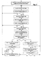
- Figure 6 provides a synthetic example of an algorithm for to perform these functions. It is synthetic because it only gives the general logic of the control and piloting of the operation of the torch, because fall under a programming obvious: either the estimation of the projection characteristics, the choice of the characteristics projection parameters and corresponding power parameters to be corrected as well as the calculation of this correction.
- the torch used is a plasma thermal projection torch with external injection and more precisely the F4MB model marketed by the company Switzerland whose name is Sulzer Metco.
- the torch is used within substantially common operating ranges so that the same equations can be used.
- the operation of the torch is only limited by the maximum dissipated power, ie 55kw. If we adopt a safety margin of 10kw, the torch will not be used beyond 45kw and the arc intensity l will be conditioned by the following formula: l ⁇ 45000 / V V being the voltage of the plasma arc expressed in volts and given to the computer 100 by the control cabinet 30 via the connection 120 between the control cabinet 30 and the computer 100.
- the minimum arc intensity as well as the normal operating ranges of the other supply parameters, namely Ar, H 2 and Ar carrier, correspond to the domains in which these equations are valid.
- the optimal ranges and the acceptable ranges, each expressed by a minimum value and a maximum value, of Imax and T are as follows: Projection characteristics Priority order Acceptable ranges min / max Optimal mini / max ranges I max [0.255] 1 0/40 0/20 T (° C) 2 190/280 190/220
- the deposit must have a hardness at least equal to 120Hv, this deposit being carried out with the torch and the composition of the aforementioned deposit.
- the optimal and acceptable ranges expressed in terms of minimum / maximum values, L and I max are as follows: Projection characteristics Priority order Acceptable ranges min / max Optimal mini / max ranges L (mm) 1 2 / 9.8 2/5 I max [0.255] 2 20/180 20/100
- the initial values of the power supply parameters and the normal operating ranges expressed in terms of minimum / maximum value are given by the following table: Power settings Initial values Minimum / maximum operating ranges No correction I (A) 450 360/540 ⁇ 10 Ar (L / min) 45 36/54 ⁇ 1 H2 (L / min) 15 12/18 ⁇ 0.5 Ar carrier (L / min) 2 , 5 2/3 ⁇ 0.1
- This third quantified example combines the two previous examples, the deposit having to have an oxide content at most equal to 2% and a hardness at least equal to 120Hv, this deposit being carried out with the torch and the composition of the deposit mentioned above.
- the residual stresses of the deposit must be in compression and limited to -400 MPa (megaPascals), this deposit being carried out with the torch and the composition of the aforementioned deposit.
- T -417.125 + 3.7875 * Ar + 61.5625 * H 2 + 0.729545 * l + 51.25 * Ar carrier -0.380208 * Ar * H 2 - 0.00244318 * Ar * l -0.0625 * Ar * Carrier back -0.0260417 * H 2 * W -6.77083 * H 2 * Carrier back - 0.0352273 * L * Carrier back
- the optimal and acceptable ranges expressed in terms of minimum / maximum values, L and T are as follows: Projection characteristics Acceptable ranges min / max Optimal mini / max ranges T (° C) 280/360 ° C 280/300 ° C
- the optimal ranges and the acceptable ranges, expressed in terms of minimum / maximum values of P and of I max are as follows: Projection characteristics Priority order Acceptable ranges min / max Optimal mini / max ranges P (mm) 1 -5 / 1.2 -5 / 1 I max [0.255] 2 20/100 20/50
- the initial values of the power supply parameters and the normal operating ranges expressed in terms of minimum / maximum value are given by the following table: Power settings Initial values Minimum / maximum operating ranges No correction I (A) 650 520/780 10 Ar (L / min) 45 36/54 1 H2 (L / min) 120 96/144 0.5 Ar carrier (L / min) 2.3 1.8 / 2.8 0.1
- the invention makes it possible to simultaneously guarantee several deposit characteristics insofar as the ranges of projection characteristics established for each characteristic of the deposit. Since these ranges do not overlap, it must then enlarge them and accept a greater dispersion in some characteristics of the deposit.
- the invention can be easily implemented with a commercial microcomputer equipped with appropriate interfaces to collect measurements of the characteristics of projection and to transmit new values of the power parameters to the control cabinet.
- Other equivalent IT architectures are possible and do not depart from the scope of the invention.
- IT resources can be those of a workstation shared by several machines.
- the invention applies to any type of thermal spray torch since the measurements used for piloting are made on the effects of the torch, in the occurrence on the jet it produces and on the temperature of the deposit.
- the proposed database is the preferred form of implementation of the invention but is not essential. Indeed, a more primitive solution consisting in introducing each time into the computer the data necessary for a thermal projection operation is also conceivable.
- the example of an information system proposed is simple and makes it possible to organize the information necessary for a thermal spraying operation. More elaborate models limiting the repetition of information are also possible. Sometimes it may be necessary to relate the operating range, the correction step or the order of priority to the equation - power parameter relationship, but the examples offered here do not require it.
- the sensors must be able to follow the execution of the projection thermal.
- these sensors will advantageously attached to the torch but they can also follow the movements of the torch by other ways.
- the claims also cover the case of an installation in which the torch would be fixed and the part to be coated movable in front of the torch.
Landscapes
- Engineering & Computer Science (AREA)
- Physics & Mathematics (AREA)
- Plasma & Fusion (AREA)
- Mechanical Engineering (AREA)
- Coating By Spraying Or Casting (AREA)
- Nozzles (AREA)
Applications Claiming Priority (2)
| Application Number | Priority Date | Filing Date | Title |
|---|---|---|---|
| FR0202524A FR2836619B1 (fr) | 2002-02-28 | 2002-02-28 | Instrument de projection thermique |
| FR0202524 | 2002-02-28 |
Publications (3)
| Publication Number | Publication Date |
|---|---|
| EP1340579A2 true EP1340579A2 (de) | 2003-09-03 |
| EP1340579A3 EP1340579A3 (de) | 2003-12-17 |
| EP1340579B1 EP1340579B1 (de) | 2006-08-16 |
Family
ID=27676156
Family Applications (1)
| Application Number | Title | Priority Date | Filing Date |
|---|---|---|---|
| EP03290477A Expired - Lifetime EP1340579B1 (de) | 2002-02-28 | 2003-02-28 | Thermische Spritzeinrichtung |
Country Status (6)
| Country | Link |
|---|---|
| US (1) | US7404860B2 (de) |
| EP (1) | EP1340579B1 (de) |
| CA (1) | CA2476635C (de) |
| DE (1) | DE60307531T2 (de) |
| FR (1) | FR2836619B1 (de) |
| WO (1) | WO2003072292A2 (de) |
Cited By (1)
| Publication number | Priority date | Publication date | Assignee | Title |
|---|---|---|---|---|
| US8563890B2 (en) | 2004-10-29 | 2013-10-22 | United Technologies Corporation | Method and apparatus for microplasma spray coating a portion of a turbine vane in a gas turbine engine |
Families Citing this family (12)
| Publication number | Priority date | Publication date | Assignee | Title |
|---|---|---|---|---|
| US7084367B2 (en) | 2003-10-09 | 2006-08-01 | Illinois Tool Works Inc. | Temperature indicating consumable |
| US7226510B2 (en) * | 2003-10-27 | 2007-06-05 | Fujifilm Corporation | Film forming apparatus |
| US20070023402A1 (en) * | 2005-07-26 | 2007-02-01 | United Technologies Corporation | Methods for repairing workpieces using microplasma spray coating |
| US7763823B2 (en) | 2004-10-29 | 2010-07-27 | United Technologies Corporation | Method and apparatus for microplasma spray coating a portion of a compressor blade in a gas turbine engine |
| JP4664054B2 (ja) * | 2004-12-09 | 2011-04-06 | 富士フイルム株式会社 | 成膜装置 |
| US20080166489A1 (en) * | 2005-08-04 | 2008-07-10 | United Technologies Corporation | Method for microstructure control of ceramic thermal spray coating |
| US20140094950A1 (en) * | 2007-03-01 | 2014-04-03 | MTU Aero Engines AG | Method for the production of an abradable spray coating |
| DE102007010049B4 (de) * | 2007-03-01 | 2011-01-13 | Mtu Aero Engines Gmbh | Verfahren zum Herstellen eines einlauffähigen Spritzbelags |
| KR100860473B1 (ko) * | 2007-04-18 | 2008-09-26 | 에스엔유 프리시젼 주식회사 | 플라즈마 모니터링장치 |
| DE102012112488B4 (de) * | 2012-12-18 | 2017-07-13 | Gebr. Heller Maschinenfabrik Gmbh | Lichtbogen-Drahtspritz-Beschichtungsverfahren für Zylinderbohrungen von Verbrennungsmotoren |
| DE102014220180A1 (de) * | 2014-10-06 | 2016-06-09 | Siemens Aktiengesellschaft | Überwachung und Steuerung eines Beschichtungsvorgangs anhand einer Wärmeverteilung auf dem Werkstück |
| US11919026B1 (en) * | 2018-05-31 | 2024-03-05 | Flame-Spray Industries, Inc. | System, apparatus, and method for deflected thermal spraying |
Citations (3)
| Publication number | Priority date | Publication date | Assignee | Title |
|---|---|---|---|---|
| JPH0318484A (ja) * | 1989-06-16 | 1991-01-28 | Daido Steel Co Ltd | 立体物造形方法およびそれに用いる装置 |
| JPH10153554A (ja) * | 1996-11-22 | 1998-06-09 | Horiba Ltd | Icpによる形態別元素分析方法 |
| USRE36926E (en) * | 1994-10-31 | 2000-10-31 | United Technologies Corporation | Welding control using fuzzy logic analysis of video imaged puddle dimensions |
Family Cites Families (5)
| Publication number | Priority date | Publication date | Assignee | Title |
|---|---|---|---|---|
| EP0837305A1 (de) * | 1996-10-21 | 1998-04-22 | Sulzer Metco AG | Einrichtung sowie Verfahren zur Überwachung des Beschichtungsprozesses einer thermischen Beschichtungsvorrichtung |
| CA2241761C (en) * | 1997-06-27 | 2007-03-06 | Omega Engineering, Inc. | Sighting system and method for temperature measuring |
| US6377400B1 (en) * | 1999-07-02 | 2002-04-23 | Milton Bernard Hollander | Laser sighting beam modification for measuring or treatment instrument |
| US6640878B2 (en) * | 2001-04-18 | 2003-11-04 | Ford Motor Company | Automated spray form cell |
| US6967304B2 (en) * | 2002-04-29 | 2005-11-22 | Cyber Materials Llc | Feedback enhanced plasma spray tool |
-
2002
- 2002-02-28 FR FR0202524A patent/FR2836619B1/fr not_active Expired - Fee Related
-
2003
- 2003-02-28 EP EP03290477A patent/EP1340579B1/de not_active Expired - Lifetime
- 2003-02-28 CA CA2476635A patent/CA2476635C/fr not_active Expired - Lifetime
- 2003-02-28 WO PCT/FR2003/000649 patent/WO2003072292A2/fr active Application Filing
- 2003-02-28 DE DE60307531T patent/DE60307531T2/de not_active Expired - Lifetime
- 2003-02-28 US US10/505,782 patent/US7404860B2/en not_active Expired - Lifetime
Patent Citations (3)
| Publication number | Priority date | Publication date | Assignee | Title |
|---|---|---|---|---|
| JPH0318484A (ja) * | 1989-06-16 | 1991-01-28 | Daido Steel Co Ltd | 立体物造形方法およびそれに用いる装置 |
| USRE36926E (en) * | 1994-10-31 | 2000-10-31 | United Technologies Corporation | Welding control using fuzzy logic analysis of video imaged puddle dimensions |
| JPH10153554A (ja) * | 1996-11-22 | 1998-06-09 | Horiba Ltd | Icpによる形態別元素分析方法 |
Non-Patent Citations (4)
| Title |
|---|
| CHEN ET AL.: "intelligent methodology for sensing, modeling and control of pulsed gtaw: part I - bead-on-plate welding" WELDING RESEARCH, juin 2000 (2000-06), pages 151s-163s, XP000954653 * |
| DOUMANIDIS ET AL.: "distributed-parameter control of the heat source trajectory in thermal materials processing" JOURNAL OF MANUFACTURING SCIENCE AND ENGINEERING, vol. 118, novembre 1996 (1996-11), pages 571-578, XP000635785 * |
| PATENT ABSTRACTS OF JAPAN vol. 015, no. 138 (M-1100), 8 avril 1991 (1991-04-08) & JP 03 018484 A (DAIDO STEEL CO LTD;OTHERS: 01), 28 janvier 1991 (1991-01-28) * |
| PATENT ABSTRACTS OF JAPAN vol. 1998, no. 11, 30 septembre 1998 (1998-09-30) & JP 10 153554 A (HORIBA LTD), 9 juin 1998 (1998-06-09) * |
Cited By (1)
| Publication number | Priority date | Publication date | Assignee | Title |
|---|---|---|---|---|
| US8563890B2 (en) | 2004-10-29 | 2013-10-22 | United Technologies Corporation | Method and apparatus for microplasma spray coating a portion of a turbine vane in a gas turbine engine |
Also Published As
| Publication number | Publication date |
|---|---|
| CA2476635C (fr) | 2010-12-07 |
| FR2836619A1 (fr) | 2003-08-29 |
| WO2003072292A3 (fr) | 2004-03-04 |
| FR2836619B1 (fr) | 2004-04-16 |
| US7404860B2 (en) | 2008-07-29 |
| EP1340579A3 (de) | 2003-12-17 |
| DE60307531T2 (de) | 2007-04-05 |
| WO2003072292A2 (fr) | 2003-09-04 |
| EP1340579B1 (de) | 2006-08-16 |
| DE60307531D1 (de) | 2006-09-28 |
| CA2476635A1 (fr) | 2003-09-04 |
| US20050223977A1 (en) | 2005-10-13 |
Similar Documents
| Publication | Publication Date | Title |
|---|---|---|
| EP1340580B1 (de) | Einrichtung zum thermischen Spritzen | |
| EP1340579B1 (de) | Thermische Spritzeinrichtung | |
| Chivel et al. | On-line temperature monitoring in selective laser sintering/melting | |
| CA2892848C (fr) | Procede de fabrication d'une piece par fusion de poudre, les particules de poudre arrivant froides dans le bain | |
| EP1340578B1 (de) | Thermische Spritzeinrichtung | |
| US20100140236A1 (en) | Laser machining system and method | |
| Sdvizhenskii et al. | Online laser-induced breakdown spectroscopy for metal-particle powder flow analysis during additive manufacturing | |
| Richter et al. | Real-time measurement of temperature and volume of the weld pool in wire-arc additive manufacturing | |
| Zhang et al. | Anomaly detection in laser metal deposition with photodiode-based melt pool monitoring system | |
| EP3615703B1 (de) | Ziel zur erzeugung einer farbigen verglasung | |
| Brandau et al. | Angular dependence of coaxial and quasi-coaxial monitoring systems for process radiation analysis in laser materials processing | |
| JP4095556B2 (ja) | 溶射器 | |
| Salehi | Sensing and control of Nd: YAG laser cladding process | |
| US20210170528A1 (en) | Determining a parameter of a melt pool during additive manufacturing | |
| JP2005525464A (ja) | 溶射装置 | |
| Valdiande Gutiérrez et al. | Laser metal deposition on-line monitoring via plasma emission spectroscopy and spectral correlation techniques |
Legal Events
| Date | Code | Title | Description |
|---|---|---|---|
| PUAI | Public reference made under article 153(3) epc to a published international application that has entered the european phase |
Free format text: ORIGINAL CODE: 0009012 |
|
| 17P | Request for examination filed |
Effective date: 20030322 |
|
| AK | Designated contracting states |
Kind code of ref document: A2 Designated state(s): AT BE BG CH CY CZ DE DK EE ES FI FR GB GR HU IE IT LI LU MC NL PT SE SI SK TR |
|
| AX | Request for extension of the european patent |
Extension state: AL LT LV MK RO |
|
| PUAL | Search report despatched |
Free format text: ORIGINAL CODE: 0009013 |
|
| AK | Designated contracting states |
Kind code of ref document: A3 Designated state(s): AT BE BG CH CY CZ DE DK EE ES FI FR GB GR HU IE IT LI LU MC NL PT SE SI SK TR |
|
| AX | Request for extension of the european patent |
Extension state: AL LT LV MK RO |
|
| AKX | Designation fees paid |
Designated state(s): CH DE FR GB IT LI NL |
|
| 17Q | First examination report despatched |
Effective date: 20041215 |
|
| GRAP | Despatch of communication of intention to grant a patent |
Free format text: ORIGINAL CODE: EPIDOSNIGR1 |
|
| GRAS | Grant fee paid |
Free format text: ORIGINAL CODE: EPIDOSNIGR3 |
|
| GRAA | (expected) grant |
Free format text: ORIGINAL CODE: 0009210 |
|
| AK | Designated contracting states |
Kind code of ref document: B1 Designated state(s): CH DE FR GB IT LI NL |
|
| PG25 | Lapsed in a contracting state [announced via postgrant information from national office to epo] |
Ref country code: IT Free format text: LAPSE BECAUSE OF FAILURE TO SUBMIT A TRANSLATION OF THE DESCRIPTION OR TO PAY THE FEE WITHIN THE PRESCRIBED TIME-LIMIT;WARNING: LAPSES OF ITALIAN PATENTS WITH EFFECTIVE DATE BEFORE 2007 MAY HAVE OCCURRED AT ANY TIME BEFORE 2007. THE CORRECT EFFECTIVE DATE MAY BE DIFFERENT FROM THE ONE RECORDED. Effective date: 20060816 |
|
| REG | Reference to a national code |
Ref country code: GB Ref legal event code: FG4D Free format text: NOT ENGLISH |
|
| GBT | Gb: translation of ep patent filed (gb section 77(6)(a)/1977) |
Effective date: 20060816 |
|
| REG | Reference to a national code |
Ref country code: CH Ref legal event code: NV Representative=s name: MICHELI & CIE INGENIEURS-CONSEILS Ref country code: CH Ref legal event code: EP |
|
| REF | Corresponds to: |
Ref document number: 60307531 Country of ref document: DE Date of ref document: 20060928 Kind code of ref document: P |
|
| PLBE | No opposition filed within time limit |
Free format text: ORIGINAL CODE: 0009261 |
|
| STAA | Information on the status of an ep patent application or granted ep patent |
Free format text: STATUS: NO OPPOSITION FILED WITHIN TIME LIMIT |
|
| 26N | No opposition filed |
Effective date: 20070518 |
|
| REG | Reference to a national code |
Ref country code: FR Ref legal event code: TP |
|
| REG | Reference to a national code |
Ref country code: GB Ref legal event code: 732E Free format text: REGISTERED BETWEEN 20120419 AND 20120425 |
|
| REG | Reference to a national code |
Ref country code: DE Ref legal event code: R082 Ref document number: 60307531 Country of ref document: DE Representative=s name: MITSCHERLICH & PARTNER PATENT- UND RECHTSANWAE, DE |
|
| REG | Reference to a national code |
Ref country code: DE Ref legal event code: R081 Ref document number: 60307531 Country of ref document: DE Owner name: SNECMA, FR Free format text: FORMER OWNER: SNECMA SERVICES, PARIS, FR Effective date: 20121005 Ref country code: DE Ref legal event code: R082 Ref document number: 60307531 Country of ref document: DE Representative=s name: MITSCHERLICH & PARTNER PATENT- UND RECHTSANWAE, DE Effective date: 20121005 Ref country code: DE Ref legal event code: R082 Ref document number: 60307531 Country of ref document: DE Representative=s name: MITSCHERLICH, PATENT- UND RECHTSANWAELTE PARTM, DE Effective date: 20121005 Ref country code: DE Ref legal event code: R082 Ref document number: 60307531 Country of ref document: DE Representative=s name: MITSCHERLICH, PATENT- UND RECHTSANWAELTE, PART, DE Effective date: 20121005 |
|
| REG | Reference to a national code |
Ref country code: FR Ref legal event code: PLFP Year of fee payment: 14 |
|
| REG | Reference to a national code |
Ref country code: FR Ref legal event code: PLFP Year of fee payment: 15 |
|
| REG | Reference to a national code |
Ref country code: FR Ref legal event code: CD Owner name: SNECMA, FR Effective date: 20170713 |
|
| REG | Reference to a national code |
Ref country code: FR Ref legal event code: PLFP Year of fee payment: 16 |
|
| PGFP | Annual fee paid to national office [announced via postgrant information from national office to epo] |
Ref country code: GB Payment date: 20220124 Year of fee payment: 20 Ref country code: DE Payment date: 20220119 Year of fee payment: 20 Ref country code: CH Payment date: 20220120 Year of fee payment: 20 |
|
| PGFP | Annual fee paid to national office [announced via postgrant information from national office to epo] |
Ref country code: NL Payment date: 20220121 Year of fee payment: 20 Ref country code: IT Payment date: 20220119 Year of fee payment: 20 Ref country code: FR Payment date: 20220119 Year of fee payment: 20 |
|
| REG | Reference to a national code |
Ref country code: CH Ref legal event code: PL Ref country code: DE Ref legal event code: R071 Ref document number: 60307531 Country of ref document: DE |
|
| REG | Reference to a national code |
Ref country code: NL Ref legal event code: MK Effective date: 20230227 |
|
| REG | Reference to a national code |
Ref country code: GB Ref legal event code: PE20 Expiry date: 20230227 |
|
| PG25 | Lapsed in a contracting state [announced via postgrant information from national office to epo] |
Ref country code: GB Free format text: LAPSE BECAUSE OF EXPIRATION OF PROTECTION Effective date: 20230227 |