EP1340579A2 - Thermal spraying apparatus - Google Patents
Thermal spraying apparatus Download PDFInfo
- Publication number
- EP1340579A2 EP1340579A2 EP03290477A EP03290477A EP1340579A2 EP 1340579 A2 EP1340579 A2 EP 1340579A2 EP 03290477 A EP03290477 A EP 03290477A EP 03290477 A EP03290477 A EP 03290477A EP 1340579 A2 EP1340579 A2 EP 1340579A2
- Authority
- EP
- European Patent Office
- Prior art keywords
- jet
- torch
- projection
- computer
- instrument according
- Prior art date
- Legal status (The legal status is an assumption and is not a legal conclusion. Google has not performed a legal analysis and makes no representation as to the accuracy of the status listed.)
- Granted
Links
Images

Classifications
-
- B—PERFORMING OPERATIONS; TRANSPORTING
- B23—MACHINE TOOLS; METAL-WORKING NOT OTHERWISE PROVIDED FOR
- B23K—SOLDERING OR UNSOLDERING; WELDING; CLADDING OR PLATING BY SOLDERING OR WELDING; CUTTING BY APPLYING HEAT LOCALLY, e.g. FLAME CUTTING; WORKING BY LASER BEAM
- B23K10/00—Welding or cutting by means of a plasma
- B23K10/006—Control circuits therefor
Definitions
- the invention relates to the coating of surfaces by thermal spraying of materials molten using a thermal spray torch, hereinafter called a torch, and more particularly to a thermal spraying instrument comprising a device for control and piloting of thermal spraying.
- Thermal spraying is a well known process for coating a solid surface with a material having a high melting point. It consists in melting the material in a flow of hot gas at high speed directed on the surface, the gas flow causing the pulverization of the material in fine molten droplets and the entrainment of the droplets towards the surface, the droplets still at the molten state crashing onto the surface, the droplets adhering to this surface and solidifying on contact.
- the flow of gas charged with molten droplets is called a jet.
- the coating is obtained by successive passes by moving the jet relative to the surface.
- Thermal spraying can be used for different purposes: decoration, thermal barrier, protection against oxidation or chemical corrosion, reloading of material, increase in the mechanical characteristics of the surface, in particular its resistance to abrasion, etc.
- the projected material can be a pure metal such as molybdenum or titanium, a metallic alloy such as NiCr, NiAl, NiCrAIY, a ceramic such as Cr2O3 or ZrO2, a carbide such as WC or Cr3C2, or a cermet such Cr3C2 / NiCr.
- the so-called "flame" thermal projection consists in producing a flame by the combustion of high calorific gases such as acetylene and oxygen, the rise of temperature producing a high speed gas stream into which the material to be sprayed in the form of powder or wire. Matter melts on contact with flame, pulverizes into fine droplets in the flow of hot combustion gases and is driven by this flow to form the jet.
- high calorific gases such as acetylene and oxygen
- the thermal projection called "by arc-wire” consists in producing an electric arc between two son of the material to be projected and to pass a flow of neutral gas, such as argon Ar, to high speed on the electric arc.
- the material of the wires liquefies in the presence of the arc electric, is sprayed into fine droplets in the flow of hot combustion gases and is driven by this flow to form the jet.
- the so-called “plasma arc” thermal projection consists in producing heat by maintaining an electric arc in a stream of plasma gas, the formation of plasma causing a sharp rise in the temperature of the gas, and to inject into this flow the powder material to be sprayed, this powder being fluidized and transported by a gas neutral says "carrier”.
- the assembly consisting of the plasma gas, the carrier gas and the molten material in fine droplets in contact with the plasma gas forms the jet.
- the jet at the exit of the torch has the shape of a diverging cone. Because of the high temperatures implemented, a torch gradually degrades in operation, this degradation causing drifts in its functioning as well as deformations and deviations of the jet. In some types of plasma arc torch, powder injection is done at the exit of the torch transverse to the gas flow plasmagen, which causes a normal deflection of the jet,
- the torch is usually small in order to be conveniently moved in front of the surface to be covered.
- This torch is connected to a control cabinet which supplies it with electric current and the various ingredients necessary for its operation. Through ingredients means the gases and materials described above.
- the quality criteria for a thermal spray deposit are usually its hardness, its adhesion to the coated surface, its porosity, the absence of cracks, the rate unfounded and, in the case of metallic materials, its oxide level.
- rate means the proportion of the material constituting the deposit that has not passed by the molten state.
- the quality of the deposit and the yield of the deposit operation obviously depend on the material used but also the setting and type of torch.
- the material flow by example in grams per minute, is obviously a parameter common to all torches.
- the gas flow rates must also be adjusted fuel and oxidizer expressed for example in liters per minute.
- the arc intensity in amps and the gas flow must also be adjusted.
- a constant quality of deposit is difficult to ensure because the torch and its supply of ingredients are subject to uncertainties and drifts over time which modify obviously this quality.
- During coating operations it is also necessary periodically carry out checks on samples and modify the adjustments, or even change the torch if necessary. Indeed, a torch degrades gradually in operation, especially in its hot parts such as the nozzle ejection, these degradations being able to derive the characteristics of the torch and deform or move the jet.
- These checks must be frequent in order to be able to detect sufficiently early the appearance of a drift and to be able to modify the torch settings, before the quality of the deposit has itself drifted outside acceptable limits.
- These controls and these adjustments obviously take time and reduce the productivity of installation.
- a first problem to solve is to verify that the torch is able to ensure a deposit whose characteristics are in accordance with what was planned, this verification that must necessarily be done in real time during a projection operation thermal, and also correct in real time the operation of this torch when drifts are noted.
- a third problem is to automatically stop the torch when it is no longer in use. able to function normally and therefore risks producing defective coatings.
- the computer also measures and processes the position P of the jet, P also constituting a projection characteristic, an order of priority being defined in the treatment of the projection characteristics, the treatment of the width L of the jet remaining the highest priority, the camera being capable of observing the jet with a resolution at least equal to 0.5 mm, P being, to within a constant value P 0 , the mean of the distribution of the luminance of the jet along a geometric line transverse to the jet.
- P is, to within a constant value P 0 , the mean of the distribution of the luminance of the jet along a geometric line transverse to the jet.
- the computer also measures and processes the maximum intensity I max of the jet, this measurement I max then also constituting a projection characteristic, the computer being able to process the projection characteristics with an order of priority, the processing of the width L of the jet being the highest priority, the processing of the maximum intensity I max of the jet arriving in priority second.
- the computer is able to process the projection characteristics with an order of priority, the processing of the width L of the jet being the highest priority, the processing of the maximum intensity I max of the jet arriving in priority second.
- the camera will advantageously be of the CCD type, the accumulation of charge in the pixels of the matrix having the effect of filtering the high-frequency vibrations of the jet and, as a result, improving the estimation of the characteristics of the jet, and consequently having better control thermal projection. Measurements can be made simply in the visible light spectrum.
- we will take a camera offering images of the jet with a resolution at least equal to 0.1mm in order to better master the characteristics of projection and by repercussion the characteristics of the deposits carried out.
- the camera, the pyrometer and the computer means used are widespread in the trade and inexpensive, which thus solves the second problem.
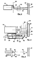
- the thermal projection instrument 10 comprises a thermal projection torch 12 with a geometric axis 14 projecting along this axis geometric 14 a jet 16 consisting of a flow of hot gas charged with droplets of the material to be projected in fusion: metal, metallic alloy, ceramic or cermet.
- Jet 16 is diverging and usually has the shape of a cone of revolution centered on the axis geometric 14.
- Sometimes a very bright flame 17 emerges from the torch 12 in the area of the top of the cone formed by the jet 16. In the case of plasma torches, this flame 17 can reach a temperature of 8000 ° K. Beyond this flame 17, the jet is also luminous but this luminosity does not come now basically just droplets of molten material.
- Jet 16 is normally centered on the geometric axis 14. Because of the high temperatures used in the torch 16 and despite the cooling devices integrated in these torches 16, the torches 16 degrade in particular by erosion during their operation, these degradations which can modify the characteristics of jet 16, deform jet 16 or do so deviate from the geometric axis 14.
- the torch 12 is of plasma arc type with transverse injection and includes an injector 18 with a perpendicular geometric axis 20 to the geometric axis of the torch 14, this injector 18 injecting into the jet 16 the material to spray powder using a so-called carrier gas, this injection taking place just at the outlet torch 12 in the area of the top of the cone formed by the jet 16, this injection takes place making transverse to jet 16 and causing deflection of jet 16 in the direction opposite the injector 18, the jet 16 then deviating normally from the geometric axis 14 .
- the droplets of molten material projected by the jet 16 arrive at high speed and are crushed on the surface of the part 22 to be covered, in order to form there by solidification and adhesion deposit 24 sought.
- This deposit 24 is normally constituted by layers successive, the torch 12 repeatedly sweeping the surface of the part 22. will reference 26 the surface of the part 22 exposed at a given time to the jet 16.
- the torch can be held by hand, for example for repairing engineering structures metal. It is most often used on an installation 40 preferably robotized ensuring the relative maintenance, positioning and movement of the torch 12 and of part 22 to be treated.
- the installation 40 will advantageously include a robot arm 42 supporting the torch 12 as well as a fixed or pivoting workpiece holder 44 and maintaining the piece 22 in front of the torch 12.
- the projection instrument 10 includes on-board sensors 52 attached to the torch 12 so as to follow it in its movements during thermal projection, these on-board sensors 52 thus remaining in a constant relative position relative to the torch 12.
- the on-board sensors 52 consist first of all of a CCD camera 54 capable of providing digital images of the jet 16 taken transversely or even perpendicular to this jet 16.
- the camera 54 is positioned to provide an image of the jet 16 beyond the flame 17, that is to say downstream of this flame 17, so that the image of the jet 16 is not veiled by the light of the flame 17.
- the reference 56 will be geometrical axis of shooting of the camera 54.
- the camera 54 is arranged on the side of the torch 12 and aims the jet 16 by means of a shooting mirror 58 placed at 45 ° in front of the camera 54, this shooting mirror 58 deviating at 90 ° the geometric axis of the CCD camera 56 and allowing this CCD camera 54 to see the jet 16.
- a shooting mirror 58 placed at 45 ° in front of the camera 54, this shooting mirror 58 deviating at 90 ° the geometric axis of the CCD camera 56 and allowing this CCD camera 54 to see the jet 16.
- the camera must have sufficient resolution to perceive details of 0.5mm on the jet 16. This resolution is indeed necessary to detect and measure a deviation of the 0.5mm jet. In the case of aeronautical applications, this resolution should even be at least equal to 0.1mm in order to control the characteristics of the deposit with a sufficient precision.
- the camera has a CCD (Charge Coupled) matrix Device) of 640 x 480 pixels with an exposure time ranging from 1/30 second to 1/2000 second to observe very different light intensity jets with precision sufficient and without saturation of the pixels of the matrix.
- CCD camera sensitivity can be limited to the visible spectrum. A black and white camera is sufficient but you can also use a color camera. Such a camera is commonly marketed at low cost. It suffices that it has sufficient resistance to the heat given off during of thermal projection.
- the camera 54 is positioned to see the jet 16 along a geometric axis 56 substantially orthogonal to the geometric axis 20 of the injector 18, this position allowing to better visualize the deflection of jet 16 caused by this mode injection, this position therefore making it possible to more effectively control the jet deflection 16.
- the on-board sensors 52 also consist of an optical pyrometer 70 with a geometric axis 72 and remotely measuring the thermal radiation emitted by a so-called “measuring" surface 73, the measuring surface 73 being small on the geometric axis 72
- the pyrometer 70 is directive and it is capable of being pointed on the part 22 as close as possible to the projection area 26 but without however interfering with this projection area 26, that is to say that the measurement area 73 is close to or even adjacent to the projection area 26 but does not interfere with this projection area 26.
- the pyrometer 70 has a narrow field and it is positioned so that the field comes as close as possible to the jet 16 on the part 22 without however interfering with this jet 16.
- the very bright jet 16 remains outside the field of the pyrometer and in particular of the measurement zone 73 so that the pyrometer 70 receives the thermal radiation that of the deposit 24 but not the light radiation of the jet 16 which would be likely to distort the measurement of the temperature of the deposit.
- it advantageously includes a laser sight 74 projecting a light spot on the measurement area 73.
- the measurement of thermal radiation is usually done in the infrared, that is to say in the band of electromagnetic radiation ranging from 0.8 ⁇ m to 14 ⁇ m. In the particular case of plasma arc torches, this measurement will advantageously be made in the 8 ⁇ m - 14 ⁇ m band in order to have a stable, precise and inexpensive measurement.
- FIG. 4 An example of a viewfinder 74 is illustrated in FIG. 4. The viewfinder 74 projected a narrow laser beam 78 in the geometric axis 72 of the pyrometer 70.
- the viewfinder comprises a laser diode 76 placed on the side of the pyrometer 70, the laser diode 76 emitting a laser beam 78 at the front of the pyrometer 70 parallel to its geometric axis 72, the laser beam 78 being brought back into the geometric axis of the pyrometer 72 by a conventional set of two mirrors 80 and 82, the second mirror 82 being semi-reflecting and positioned on the geometric axis of the pyrometer 72.
- the adjustment of the viewfinder does not depend on the distance between the pyrometer 70 and the surface of the part whose temperature must be measured. It will be noted that the pyrometer 70 gives an exact measurement of the temperature only for perfect black bodies.
- the on-board sensors 52 are arranged at inside a closed enclosure 90 which protects them against external agents, this enclosure 90, however, comprising openings 92 allowing the camera 54 to see the jet 16 and with the pyrometer 70 to see the surface of the part 22, this enclosure 90 comprising a pressurized air supply 94, this pressurized air exiting by the openings 92 and obstructing the penetration of dust and droplets in the enclosure during the operation of the torch 12, this dust and droplets being likely to be deposited on the sensors 52 and in particular to foul the optical components.
- the thermal projection instrument 10 also includes a computer 100 connected by connection 110 to the sensors on-board 52, that is to the camera 54 and to the pyrometer 70.
- computer 100 is capable of receiving digital images 112 in real time from camera 54 as well as temperature readings 114 from pyrometer 70.
- the computer 100 is also connected by connection 120 to the cabinet command 30.
- the computer 100 is capable of transmit the power parameters to the control cabinet 30 in real time.
- this connection 120 also, the computer is likely to receive in real time power supply parameters of the control cabinet 30, for example the voltage V of the arc in the case of a plasma torch.
- real time is meant the value information to be applied upon receipt or the current value of the information that will be transmitted.
- Computer 100 can be a commonly used microcomputer sold equipped with appropriate connection means to be able to be connected to connections 110 and 120 respectively to sensors 52 and to the control cabinet 30, this computer 100 must also have sufficient power to be able to perform treatments at the appropriate frequency.
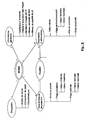
- the computer 100 also includes a base 130 containing the information necessary for controlling and steering the thermal spraying.
- the information is grouped into models, each model providing the information required to manage a deposit operation by thermal spraying with a torch, a deposition composition and specified deposit characteristics.
- the maximum luminous intensity of the jet I max is the maximum luminance of the jet 16, this maximum luminance of the jet usually being in the center of the jet 16 seen laterally from the outside and downstream of any flame 17 coming out of the torch 12.
- Luminance is a physical quantity expressable in watts per square meter and per steradian (w / m 2 / sr).
- the maximum light level of the pixels of the dot image 112 given by the matrix of the CCD camera 54 will be taken. This light level is common to known image standards such as bitmap, GIF, PSD, etc. It is usually coded on eight bits and consequently ranges from zero to 255.
- the CCD camera 54 used provides color images, that is to say in red-green-blue additive tri-color, we can simply take, but this is not compulsory, the maximum light level of the color green, this green color being the closest to the behavior of a CCD camera in black and white.
- the position of the jet P is the position of the jet relative to the geometric axis 14 of the torch 12.
- P will advantageously be the average of the distribution of the luminance of the jet also across the width of the jet 16a on image 112, for example and as previously along a line of pixels 154 perpendicular to position 14a on image 112 of the geometrical axis of torch 14.
- the temperature of the deposit T is the temperature measured by the pyrometer 70 and corrected by depending on the emissivity of the deposit.
- the CCD camera must have sufficient resolution to measure the width of the jet L and its position P with a fidelity of 0.5mm in current applications and 0.1mm in aeronautical applications. This means that the measurements must be repetitive and that they can detect deviations of 0.5mm and 0.1mm respectively in the variations in the quantities measured.
- the camera used here has a 640x480 matrix pixels.
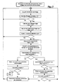
- Figure 6 provides a synthetic example of an algorithm for to perform these functions. It is synthetic because it only gives the general logic of the control and piloting of the operation of the torch, because fall under a programming obvious: either the estimation of the projection characteristics, the choice of the characteristics projection parameters and corresponding power parameters to be corrected as well as the calculation of this correction.
- the torch used is a plasma thermal projection torch with external injection and more precisely the F4MB model marketed by the company Switzerland whose name is Sulzer Metco.
- the torch is used within substantially common operating ranges so that the same equations can be used.
- the operation of the torch is only limited by the maximum dissipated power, ie 55kw. If we adopt a safety margin of 10kw, the torch will not be used beyond 45kw and the arc intensity l will be conditioned by the following formula: l ⁇ 45000 / V V being the voltage of the plasma arc expressed in volts and given to the computer 100 by the control cabinet 30 via the connection 120 between the control cabinet 30 and the computer 100.
- the minimum arc intensity as well as the normal operating ranges of the other supply parameters, namely Ar, H 2 and Ar carrier, correspond to the domains in which these equations are valid.
- the optimal ranges and the acceptable ranges, each expressed by a minimum value and a maximum value, of Imax and T are as follows: Projection characteristics Priority order Acceptable ranges min / max Optimal mini / max ranges I max [0.255] 1 0/40 0/20 T (° C) 2 190/280 190/220
- the deposit must have a hardness at least equal to 120Hv, this deposit being carried out with the torch and the composition of the aforementioned deposit.
- the optimal and acceptable ranges expressed in terms of minimum / maximum values, L and I max are as follows: Projection characteristics Priority order Acceptable ranges min / max Optimal mini / max ranges L (mm) 1 2 / 9.8 2/5 I max [0.255] 2 20/180 20/100
- the initial values of the power supply parameters and the normal operating ranges expressed in terms of minimum / maximum value are given by the following table: Power settings Initial values Minimum / maximum operating ranges No correction I (A) 450 360/540 ⁇ 10 Ar (L / min) 45 36/54 ⁇ 1 H2 (L / min) 15 12/18 ⁇ 0.5 Ar carrier (L / min) 2 , 5 2/3 ⁇ 0.1
- This third quantified example combines the two previous examples, the deposit having to have an oxide content at most equal to 2% and a hardness at least equal to 120Hv, this deposit being carried out with the torch and the composition of the deposit mentioned above.
- the residual stresses of the deposit must be in compression and limited to -400 MPa (megaPascals), this deposit being carried out with the torch and the composition of the aforementioned deposit.
- T -417.125 + 3.7875 * Ar + 61.5625 * H 2 + 0.729545 * l + 51.25 * Ar carrier -0.380208 * Ar * H 2 - 0.00244318 * Ar * l -0.0625 * Ar * Carrier back -0.0260417 * H 2 * W -6.77083 * H 2 * Carrier back - 0.0352273 * L * Carrier back
- the optimal and acceptable ranges expressed in terms of minimum / maximum values, L and T are as follows: Projection characteristics Acceptable ranges min / max Optimal mini / max ranges T (° C) 280/360 ° C 280/300 ° C
- the optimal ranges and the acceptable ranges, expressed in terms of minimum / maximum values of P and of I max are as follows: Projection characteristics Priority order Acceptable ranges min / max Optimal mini / max ranges P (mm) 1 -5 / 1.2 -5 / 1 I max [0.255] 2 20/100 20/50
- the initial values of the power supply parameters and the normal operating ranges expressed in terms of minimum / maximum value are given by the following table: Power settings Initial values Minimum / maximum operating ranges No correction I (A) 650 520/780 10 Ar (L / min) 45 36/54 1 H2 (L / min) 120 96/144 0.5 Ar carrier (L / min) 2.3 1.8 / 2.8 0.1
- the invention makes it possible to simultaneously guarantee several deposit characteristics insofar as the ranges of projection characteristics established for each characteristic of the deposit. Since these ranges do not overlap, it must then enlarge them and accept a greater dispersion in some characteristics of the deposit.
- the invention can be easily implemented with a commercial microcomputer equipped with appropriate interfaces to collect measurements of the characteristics of projection and to transmit new values of the power parameters to the control cabinet.
- Other equivalent IT architectures are possible and do not depart from the scope of the invention.
- IT resources can be those of a workstation shared by several machines.
- the invention applies to any type of thermal spray torch since the measurements used for piloting are made on the effects of the torch, in the occurrence on the jet it produces and on the temperature of the deposit.
- the proposed database is the preferred form of implementation of the invention but is not essential. Indeed, a more primitive solution consisting in introducing each time into the computer the data necessary for a thermal projection operation is also conceivable.
- the example of an information system proposed is simple and makes it possible to organize the information necessary for a thermal spraying operation. More elaborate models limiting the repetition of information are also possible. Sometimes it may be necessary to relate the operating range, the correction step or the order of priority to the equation - power parameter relationship, but the examples offered here do not require it.
- the sensors must be able to follow the execution of the projection thermal.
- these sensors will advantageously attached to the torch but they can also follow the movements of the torch by other ways.
- the claims also cover the case of an installation in which the torch would be fixed and the part to be coated movable in front of the torch.
Abstract
Description
L'invention se rapporte au revêtement de surfaces par projection thermique de matières en fusion à l'aide d'une torche de projection thermique, appelée ci-après torche, et plus particulièrement à un instrument de projection thermique comportant un dispositif de contrôle et de pilotage de la projection thermique.The invention relates to the coating of surfaces by thermal spraying of materials molten using a thermal spray torch, hereinafter called a torch, and more particularly to a thermal spraying instrument comprising a device for control and piloting of thermal spraying.
La projection thermique est un procédé bien connu pour revêtir une surface solide par
une matière présentant un point du fusion élevé. Elle consiste à fondre la matière dans un
flux de gaz chaud à grande vitesse dirigé sur la surface, le flux de gaz provoquant la
pulvérisation de la matière en fines gouttelettes fondues et l'entraínement des
gouttelettes vers la surface, les gouttelettes encore à l'état fondu s'écrasant sur la
surface, les gouttelettes adhérant à cette surface et se solidifiant à son contact. Le flux
de gaz chargé de gouttelettes en fusion est appelé jet. Le revêtement est obtenu par
passes successives en déplaçant le jet par rapport à la surface.
La projection thermique peut être utilisée dans différents buts : décoration, barrière
thermique, protection contre l'oxydation ou la corrosion chimique, rechargement de
matière, augmentation des caractéristiques mécaniques de la surface, notamment de sa
résistance à l'abrasion, etc.
La matière projeté peut être un métal pur tel le molybdène ou le titane, un aliage
métallique tel le NiCr, le NiAl, le NiCrAIY, une céramique telle le Cr2O3 ou le ZrO2, un
carbure tel le WC ou le Cr3C2, ou un cermet tel le Cr3C2/NiCr.Thermal spraying is a well known process for coating a solid surface with a material having a high melting point. It consists in melting the material in a flow of hot gas at high speed directed on the surface, the gas flow causing the pulverization of the material in fine molten droplets and the entrainment of the droplets towards the surface, the droplets still at the molten state crashing onto the surface, the droplets adhering to this surface and solidifying on contact. The flow of gas charged with molten droplets is called a jet. The coating is obtained by successive passes by moving the jet relative to the surface.
Thermal spraying can be used for different purposes: decoration, thermal barrier, protection against oxidation or chemical corrosion, reloading of material, increase in the mechanical characteristics of the surface, in particular its resistance to abrasion, etc.
The projected material can be a pure metal such as molybdenum or titanium, a metallic alloy such as NiCr, NiAl, NiCrAIY, a ceramic such as Cr2O3 or ZrO2, a carbide such as WC or Cr3C2, or a cermet such Cr3C2 / NiCr.
On connaít différents procédés de projection thermique utilisant chacun une torche particulière. We know different thermal spraying methods each using a torch special.
La projection thermique dite "à la flamme" consiste à produire une flamme par la combustion de gaz à haut pouvoir calorifique tels l'acétylène et l'oxygène, l'élévation de température produisant un courant gazeux à grande vitesse dans lequel on injecte la matière à projeter sous la forme de poudre ou de fil. La matière fond au contact de la flamme, se pulvérise en fines gouttelettes dans le flux de gaz chauds de combustion et est entraíné par ce flux pour former le jet.The so-called "flame" thermal projection consists in producing a flame by the combustion of high calorific gases such as acetylene and oxygen, the rise of temperature producing a high speed gas stream into which the material to be sprayed in the form of powder or wire. Matter melts on contact with flame, pulverizes into fine droplets in the flow of hot combustion gases and is driven by this flow to form the jet.
La projection thermique dite "par arc-fil" consiste à produire un arc électrique entre deux fils de la matière à projeter et à faire passer un flux de gaz neutre, tel de l'argon Ar, à grande vitesse sur l'arc électrique. La matière des fils se liquéfie en présence de l'arc électrique, se pulvérise en fines gouttelettes dans le flux de gaz chauds de combustion et est entraíné par ce flux pour former le jet.The thermal projection called "by arc-wire" consists in producing an electric arc between two son of the material to be projected and to pass a flow of neutral gas, such as argon Ar, to high speed on the electric arc. The material of the wires liquefies in the presence of the arc electric, is sprayed into fine droplets in the flow of hot combustion gases and is driven by this flow to form the jet.
La projection thermique dite "par arc plasma" consiste à produire de la chaleur en entretenant un arc électrique dans un flux de gaz plasmagène, la formation de plasma provoquant une forte élévation de la température du gaz, et à injecter dans ce flux la matière en poudre à projeter, cette poudre étant fluidisée et transportée par un gaz neutre dit "porteur". L'ensemble constitué par le gaz plasmagène, le gaz porteur et la matière fondue en fines gouttelettes au contact du gaz plasmagène forme le jet.The so-called "plasma arc" thermal projection consists in producing heat by maintaining an electric arc in a stream of plasma gas, the formation of plasma causing a sharp rise in the temperature of the gas, and to inject into this flow the powder material to be sprayed, this powder being fluidized and transported by a gas neutral says "carrier". The assembly consisting of the plasma gas, the carrier gas and the molten material in fine droplets in contact with the plasma gas forms the jet.
Le jet à la sortie de la torche a la forme d'un cône divergeant. A cause des hautes températures mises en oeuvre, une torche se dégrade progressivement en exploitation, cette dégradation provoquant des dérives dans son fonctionnement ainsi que des déformations et des déviations du jet. Dans certains types de torche à arc-plasma, l'injection de poudre se fait à la sortie de la torche transversalement au flux de gaz plasmagène, ce qui provoque une déviation normale du jet,The jet at the exit of the torch has the shape of a diverging cone. Because of the high temperatures implemented, a torch gradually degrades in operation, this degradation causing drifts in its functioning as well as deformations and deviations of the jet. In some types of plasma arc torch, powder injection is done at the exit of the torch transverse to the gas flow plasmagen, which causes a normal deflection of the jet,
La torche est habituellement de petite taille afin d'être commodément déplacée devant la surface à recouvrir. Cette torche est reliée à une armoire de commande qui l'alimente en courant électrique et en les différents ingrédients nécessaires à son fonctionnement. Par ingrédients, on entend les gaz et les matières décrites ci-dessus.The torch is usually small in order to be conveniently moved in front of the surface to be covered. This torch is connected to a control cabinet which supplies it with electric current and the various ingredients necessary for its operation. Through ingredients means the gases and materials described above.
Les critères de qualité d'un dépôt effectué par projection thermique sont habituellement sa dureté, son adhérence a la surface revêtue, sa porosité, l'absence de criques, le taux d'infondus et, dans le cas de matières métalliques, son taux d'oxyde. Par le terme "taux d'infondus" on entend la proportion de la matière constituant le dépôt qui n'est pas passé par l'état fondu. On fait également attention au rendement de la projection, c'est à dire à la proportion de la matière utilisée qui constituera effectivement le dépôt, le reste de la matière se perdant sur les parois entourant l'installation de projection thermique.The quality criteria for a thermal spray deposit are usually its hardness, its adhesion to the coated surface, its porosity, the absence of cracks, the rate unfounded and, in the case of metallic materials, its oxide level. By the term "rate "means the proportion of the material constituting the deposit that has not passed by the molten state. We also pay attention to the efficiency of the projection, i.e. the proportion of the material used which will effectively constitute the deposit, the rest of the material lost on the walls surrounding the thermal spraying installation.
La qualité du dépôt et le rendement de l'opération de dépôt dépendent évidemment de la matière employée mais aussi du réglage et du type de la torche. Le débit de matière, par exemple en grammes par minute, est évidemment un paramètre commun à toutes les torches. Dans le cas de la projection à la flamme, il faut régler aussi les débits de gaz carburant et comburant exprimés par exemple en litres par minute. Dans le cas d'une projection par arc-fil, il faut régler aussi l'intensité d'arc en ampères et le débit de gaz. Dans le cas d'une projection par arc-plasma, il faut régler aussi l'intensité d'arc, le débit de gaz plasmagène et le débit de gaz porteur.The quality of the deposit and the yield of the deposit operation obviously depend on the material used but also the setting and type of torch. The material flow, by example in grams per minute, is obviously a parameter common to all torches. In the case of flame projection, the gas flow rates must also be adjusted fuel and oxidizer expressed for example in liters per minute. In the case of a projection by arc-wire, the arc intensity in amps and the gas flow must also be adjusted. In the case of a plasma arc projection, it is also necessary to adjust the arc intensity, the flow plasma gas and carrier gas flow.
Une qualité de dépôt constante est difficile à assurer car la torche et son alimentation en ingrédients font l'objet d'incertitudes et de dérives dans le temps qui modifient évidemment cette qualité. Avant d'effectuer des opérations d'enduction, il est nécessaire d'essayer la torche sur des échantillons et d'ajuster les réglages en cas de besoin. Mais cela ne suffit pas. Pendant les opérations d'enduction, II est également nécessaire d'effectuer périodiquement des contrôles à partir d'échantillons et de modifier les réglages, voire de changer la torche en cas de besoin. En effet, une torche se dégrade progressivement en exploitation, notamment dans ses parties chaudes telles la buse d'éjection, ces dégradations pouvant faire dériver les caractéristiques de la torche et déformer ou déplacer le jet. Ces contrôles doivent être fréquents afin de pouvoir détecter suffisamment tôt l'apparition d'une dérive et de pouvoir modifier les réglages de la torche, avant que la qualité du dépôt ait elle-même dérivé en dehors des limites acceptables. Ces contrôles et ces réglages prennent évidemment du temps et réduisent la productivité de l'installation. De plus, dans le cas d'opérations d'enduction longues, il peut être nécessaire de l'interrompre pour contrôler la torche ou la qualité du dépôt et, s'il y a lieu, modifier le réglage de la torche ou de la remplacer.A constant quality of deposit is difficult to ensure because the torch and its supply of ingredients are subject to uncertainties and drifts over time which modify obviously this quality. Before performing coating operations, it is necessary try the torch on samples and adjust the settings if necessary. But It's not enough. During coating operations, it is also necessary periodically carry out checks on samples and modify the adjustments, or even change the torch if necessary. Indeed, a torch degrades gradually in operation, especially in its hot parts such as the nozzle ejection, these degradations being able to derive the characteristics of the torch and deform or move the jet. These checks must be frequent in order to be able to detect sufficiently early the appearance of a drift and to be able to modify the torch settings, before the quality of the deposit has itself drifted outside acceptable limits. These controls and these adjustments obviously take time and reduce the productivity of installation. In addition, in the case of long coating operations, it can be necessary to interrupt it to check the torch or the quality of the deposit and, if necessary, change the torch setting or replace it.
Un premier problème à résoudre est de vérifier que la torche est en mesure d'assurer un dépôt dont les caractéristiques sont conformes à ce qui était prévu, cette vérification devant nécessairement s'effectuer en temps réel pendant une opération de projection thermique, et de corriger également en temps réel le fonctionnement de cette torche lorsque des dérives sont constatées.A first problem to solve is to verify that the torch is able to ensure a deposit whose characteristics are in accordance with what was planned, this verification that must necessarily be done in real time during a projection operation thermal, and also correct in real time the operation of this torch when drifts are noted.
Un second problème est d'arriver à ces résultats par des moyens peu coûteux. A second problem is to achieve these results by inexpensive means.
Un troisième problème est d'arrêter automatiquement la torche lorsqu'elle n'est plus en mesure de fonctionner normalement et qu'elle risque en conséquence de produire des revêtements défectueux.A third problem is to automatically stop the torch when it is no longer in use. able to function normally and therefore risks producing defective coatings.
Pour résoudre le premier problème, l'invention propose un instrument de projection
thermique comportant une torche de projection thermique, la torche étant susceptible de
projeter un jet selon son axe géométrique, le jet étant constitué d'un flux de gaz à
température élevée chargé de particules en fusion du matériau à projeter, l'instrument
comportant une armoire de commande alimentant en ingrédients la torche en appliquant
les paramètres d'alimentation qui lui sont communiqués, l'instrument comportant un
ordinateur communiquant à l'armoire de commande les paramètres d'alimentation par
l'intermédiaire d'une connexion armoire - ordinateur, l'instrument comportant des capteurs
aptes à suivre les déplacements de la torche, les capteurs étant susceptible de
transmettre à l'ordinateur des information sur le fonctionnement de la torche, cette
transmission s'effectuant par l'intermédiaire de la connexion capteurs - ordinateur.
Un tel instrument est remarquable en ce que :
Such an instrument is remarkable in that:
Avantageusement, l'ordinateur mesure et traite également la position P du jet, P
constituant également une caractéristique de projection, un ordre de priorité étant défini
dans le traitement des caractéristiques de projection, le traitement de la largeur L du jet
restant le plus prioritaire, la caméra étant susceptible d'observer le jet avec une résolution
au moins égale 0,5mmm, P étant, à une valeur constante P0 près, la moyenne de la
distribution de la luminance du jet suivant une ligne géométrique transversale au jet.
Une telle disposition permet de maítriser également le taux de criques du revêtement, car
il a été constaté que ce taux de criques dépend fortement de la position P du jet.Advantageously, the computer also measures and processes the position P of the jet, P also constituting a projection characteristic, an order of priority being defined in the treatment of the projection characteristics, the treatment of the width L of the jet remaining the highest priority, the camera being capable of observing the jet with a resolution at least equal to 0.5 mm, P being, to within a constant value P 0 , the mean of the distribution of the luminance of the jet along a geometric line transverse to the jet.
Such an arrangement also makes it possible to control the rate of cracks in the coating, since it has been found that this rate of cracks strongly depends on the position P of the jet.
Avantageusement encore :
Avantageusement encore, l'ordinateur mesure et traite également l'intensité maximale Imax
du jet, cette mesure Imax constituant alors également une caractéristique de projection,
l'ordinateur étant apte à traiter les caractéristiques de projection avec un ordre de priorité,
le traitement de la largeur L du jet étant le plus prioritaire, le traitement de l'intensité
maximale Imax du jet arrivant en priorité seconde.
Une telle disposition permet d'étendre le domaine de fonctionnement normal de la torche.
En effet, il a été constaté que la dureté du revêtement dépend également de l'intensité
maximale Imax du jet, mais à un moindre degré que la largeur L du jet. Ainsi, lorsqu'il n'est
plus possible de corriger L sans faire sortir les paramètres d'alimentation de leurs plage
de fonctionnement normal, la torche étant trop dégradée, l'instrument permet encore
d'agir sur l'intensité maximale Imax du jet pour garantir la dureté du revêtement choisie.Also advantageously, the computer also measures and processes the maximum intensity I max of the jet, this measurement I max then also constituting a projection characteristic, the computer being able to process the projection characteristics with an order of priority, the processing of the width L of the jet being the highest priority, the processing of the maximum intensity I max of the jet arriving in priority second.
Such an arrangement makes it possible to extend the normal operating range of the torch. Indeed, it was found that the hardness of the coating also depends on the maximum intensity I max of the jet, but to a lesser degree than the width L of the jet. Thus, when it is no longer possible to correct L without bringing the power supply parameters out of their normal operating range, the torch being too degraded, the instrument still allows to act on the maximum intensity I max of the jet to guarantee the hardness of the chosen coating.
La caméra sera avantageusement du type CCD, l'accumulation de charge dans les pixels
de la matrice ayant pour effet de filtrer les vibrations hautes fréquences du jet et pour
brésultat d'améliorer l'estimation des caractéristiques du jet, et par répercussion de mieux
maítriser la projection thermique. Les mesures peuvent se faire simplement dans le
spectre de lumière visible. Dans le cas d'applications nécessitant une grande maítrise des
procédés de fabrication, par exemple dans l'industrie aéronautique et spatiale, on prendra
une caméra offrant des images du jet avec une résolution au moins égale à o,1mm afin
de mieux maítriser les caractéristiques de projection et par répercussion les
caractéristiques des dépôts effectués.
La caméra, le pyromètre et les moyens informatiques utilisés sont répandus dans le
commerce et bon marché, ce qui résout ainsi le second problème.The camera will advantageously be of the CCD type, the accumulation of charge in the pixels of the matrix having the effect of filtering the high-frequency vibrations of the jet and, as a result, improving the estimation of the characteristics of the jet, and consequently having better control thermal projection. Measurements can be made simply in the visible light spectrum. In the case of applications requiring a great mastery of the manufacturing processes, for example in the aeronautical and space industry, we will take a camera offering images of the jet with a resolution at least equal to 0.1mm in order to better master the characteristics of projection and by repercussion the characteristics of the deposits carried out.
The camera, the pyrometer and the computer means used are widespread in the trade and inexpensive, which thus solves the second problem.
L'invention sera mieux comprise et les avantages qu'elle procure apparaítrons plus clairement au vu de la description détaillée ci-après, de quelques exemples chiffrés de mise en oeuvre et des figures annexées.The invention will be better understood and the advantages it provides will appear more clearly in view of the detailed description below, of some numerical examples of implementation and attached figures.
On décrira en premier lieu une installation type de projection thermique et le dispositif de contrôle qui lui est associé selon l'invention.We will first describe a typical thermal spraying installation and the control associated with it according to the invention.
On se reportera d'abord à la figure 1. L'instrument de projection thermique 10 comporte
une torche de projection thermique 12 d'axe géométrique 14 projetant selon cet axe
géométrique 14 un jet 16 constitué par un flux de gaz chaud chargé de gouttelettes de la
matière à projeter en fusion : métal, alliage métallique, céramique ou cermet. Le jet 16 est
divergeant et a habituellement la forme d'un cône de révolution centré sur l'axe
géométrique 14. Quelquefois, une flamme 17 très lumineuse émerge de la torche 12
dans la zone du sommet du cône formé par le jet 16. Dans le cas des torches plasma,
cette flamme 17 peut atteindre une température de 8000°K. Au delà de cette flamme 17,
le jet est également lumineux mais cette luminosité ne provient maintenant
essentiellement que des gouttelettes de matière en fusion. Le jet 16 est normalement
centré sur l'axe géométrique 14. A cause des hautes températures mises en oeuvre dans
la torche 16 et malgré les dispositifs de refroidissement intégrés dans ces torches 16, les
torches 16 se dégradent notamment par érosion pendant leur exploitation, ces
dégradations pouvant modifier les caractéristiques du jet 16, déformer le jet 16 ou le faire
dévier de l'axe géométrique 14.Reference will first be made to FIG. 1. The
On se reportera simultanément aux figures 1 et 2. La torche 12 est à arc plasma du type
à injection transversale et comporte un injecteur 18 d'axe géométrique 20 perpendiculaire
à l'axe géométrique de la torche 14, cet injecteur 18 injectant dans le jet 16 le matériau à
projeter en poudre à l'aide d'un gaz dit porteur, cette injection se faisant juste à la sortie
de la torche 12 dans la zone du sommet du cône formé par le jet 16, cette injection se
faisant transversalement au jet 16 et provoquant une déviation du jet 16 dans la direction
opposée à l'injecteur 18, le jet 16 s'écartant alors normalement de l'axe géométrique 14..Reference will be made simultaneously to FIGS. 1 and 2. The
Les gouttelettes de matière en fusion projetées par le jet 16 arrivent à grande vitesse et
s'écrasent sur la surface de la pièce 22 à recouvrir, afin d'y former par solidification et
adhérence le dépôt 24 recherché. Ce dépôt 24 est constitué normalement par couches
successives, la torche 12 balayant à plusieurs reprises la surface de la pièce 22. On
référencera 26 la surface de la pièce 22 exposée à un instant donné au jet 16.The droplets of molten material projected by the
L'instrument de projection thermique 10 comporte également un conduit 28 et une
armoire de commande 30, cette armoire de commande 30 alimentant en ingrédients la
torche 12 par l'intermédiaire du conduit 28, cette alimentation consistant à apporter à la
torche 12 les ingrédients requis pour son fonctionnement. On appellera "paramètres
d'alimentation" les débits de ces ingrédients.
Dans le cas d'une torche à arc plasma, les paramètres essentiels d'alimentation de la
torche sont :
- le courant d'arc électrique l et la tension V qui en résulte;
- le débit de chaque gaz plasmagène tels l'hydrogène H2 et l'argon Ar, exprimé par exemple en litres par minute, les litres étant considérés à la pression atmosphérique;
- le débit de matière Dm, exprimé par exemple en grammes par minute;
- le débit de gaz porteur, exprimé par exemple également en litres par minute, ce gaz étant habituellement de l'argon et étant noté Arporteur,
In the case of a plasma arc torch, the essential parameters of the torch supply are:
- the electric arc current I and the resulting voltage V;
- the flow rate of each plasma gas such as hydrogen H2 and argon Ar, for example expressed in liters per minute, the liters being considered at atmospheric pressure;
- the flow of material Dm, expressed for example in grams per minute;
- the flow rate of carrier gas, also expressed for example in liters per minute, this gas usually being argon and being denoted Ar carrier,
La torche peut être tenue à la main, par exemple pour la réfection d'ouvrages d'art
métalliques. Elle est le plus souvent utilisée sur une installation 40 de préférence
robotisée assurant le maintien, le positionnement et le déplacement relatifs de la torche
12 et de la pièce 22 à traiter. L'installation 40 comportera avantageusement un bras robot
42 soutenant la torche 12 ainsi qu'un porte pièce 44 fixe ou pivotant et maintenant la
pièce 22 devant la torche 12.The torch can be held by hand, for example for repairing engineering structures
metal. It is most often used on an
On se reportera maintenant à la figure 3. Selon l'invention, l'instrument de projection 10
comporte des capteurs embarqués 52 attachés à la torche 12 de façon à la suivre dans
ses mouvements pendant la projection thermique, ces capteurs embarqués 52 restant
ainsi dans une position relative constante par rapport à la torche 12.
Les capteurs embarqués 52 sont constitués d'abord par une caméra CCD 54 susceptible
de fournir des images numériques du jet 16 prises transversalement voire
perpendiculairement à ce jet 16. Lorsque le jet 16 présente à son début une flamme 17,
la caméra 54 est positionnée pour fournir une image du jet 16 au delà de la flamme 17,
c'est à dire en aval de cette flamme 17, afin que l'image du jet 16 ne soit pas voilée par la
lumière de la flamme 17. On référencera 56 l'axe géométrique de prise de vue de la
caméra 54. De préférence mais non obligatoirement, la caméra 54 est disposée sur le
coté de la torche 12 et vise le jet 16 par l'intermédiaire d'un miroir de prise de vue 58
disposé à 45° devant la caméra 54, ce miroir de prise de vue 58 déviant à 90° l'axe
géométrique de la caméra CCD 56 et permettant à cette caméra CCD 54 de voir le jet 16.
Une telle disposition permet ainsi de dégager le plus possible l'espace entre la torche 12
et la pièce 22.Referring now to FIG. 3. According to the invention, the
The on-
La caméra doit avoir une résolution suffisante pour percevoir des détails de 0,5mm sur le
jet 16. Cette résolution est en effet nécessaire pour détecter et mesurer une déviation du
jet de 0,5mm. Dans le cas des applications aéronautiques, cette résolution devrait même
être au moins égale à 0,1mm afin de maítriser les caractéristiques du dépôt avec une
précision suffisante. Dans cet exemple, la caméra a une matrice CCD (Charge Coupled
Device) de 640 x 480 pixels avec une durée d'exposition allant de 1/30 seconde à 1/2000
seconde pour observer des jets d'intensité lumineuse très différentes avec une précision
suffisante et sans saturation des pixels de la matrice. La sensibilité de la caméra CCD
peut être limitée au spectre visible. Une caméra noir et blanc est suffisante mais on peut
également utiliser une caméra couleur. Une telle caméra est couramment commercialisés
à faibles coût. Il suffit qu'elle présente une résistance suffisante à la chaleur dégagée lors
de la projection thermique.The camera must have sufficient resolution to perceive details of 0.5mm on the
Dans le cas où la torche 12 comportant un injecteur 18 de matière à projeter en poudre,
la caméra 54 est positionnée pour voir le jet 16 suivant un axe géométrique 56
sensiblement orthogonal à l'axe géométrique 20 de l'injecteur 18, cette position
permettant de visualiser au mieux la déviation du jet 16 provoquée par ce mode
d'injection, cette position permettant en conséquence de contrôler plus efficacement la
déviation du jet 16.In the case where the
Par rapport à des dispositifs d'acquisition classiques tels une barrette de photodiodes, la caméra CCD présente les avantages suivants.
- Lissage des vibrations haute fréquence du jet obtenu par l'effet d'accumulation des
charges dans les pixels de la matrice CCD, cette accumulation s'effectuant en
proportion de la lumière qu'ils reçoivent, ce lissage évitant de fausser les mesures et
d'introduire des instabilités dans le pilotage de la torche. En effet, les capteurs
intègrent la lumière reçue pendant la durée de l'exposition, de sorte que les variations
de la luminance du
jet 16 provenant de ces vibrations sont divisées par le rapport d/t, d étant la durée de l'exposition et t étant la période des vibrations du jet. Dans un dispositif classique, il aurait fallu disposer des filtres électroniques passe-bas sur chacun des éléments photosensibles ce qui en augmenterait l'encombrement et en limiterait le nombre. - Grande résolution sous un faible volume, soit quelques centimètres cubes.
- Dispositif bon marché et permettant de prendre et de transmettre les images à l'ordinateur par des moyens standards et couramment commercialisés.
- Smoothing of the high frequency vibrations of the jet obtained by the effect of charge accumulation in the pixels of the CCD matrix, this accumulation taking place in proportion to the light they receive, this smoothing avoiding distorting the measurements and introduce instabilities in piloting the torch. In fact, the sensors integrate the light received during the duration of the exposure, so that the variations in the luminance of the
jet 16 originating from these vibrations are divided by the ratio d / t, d being the duration of the exposure and t being the period of the jet vibrations. In a conventional device, it would have been necessary to have low-pass electronic filters on each of the photosensitive elements, which would increase their bulk and limit their number. - High resolution in a small volume, a few cubic centimeters.
- Inexpensive device and allowing to take and transmit the images to the computer by standard and commonly marketed means.
Les capteurs embarqués 52 sont constitués également par un pyromètre optique 70
d'axe géométrique 72 et mesurant à distance le rayonnement thermique émis par une
surface 73 dite "de mesure", la surface 73 de mesure étant de petites dimensions sur
l'axe géométrique 72. Le pyromètre 70 est directif et il est susceptible d'être pointé sur la
pièce 22 au plus près de la zone de projection 26 mais sans toutefois interférer avec cette
zone de projection 26, c'est à dire que la zone de mesure 73 est proche voire adjacente à
la zone de projection 26 mais n'interfère pas avec cette zone de projection 26. En
d'autres termes, le pyromètre 70 a un champ étroit et il est positionné pour que le champ
arrive au plus près du jet 16 sur la pièce 22 sans toutefois interférer avec ce jet 16. Avec
cette disposition, le jet 16 très lumineux reste extérieur au champ du pyromètre et en
particulier de la zone de mesure 73 de sorte que le pyromètre 70 reçoit le rayonnement
thermique du dépôt 24 mais pas le rayonnement lumineux du jet 16 qui serait susceptible
de fausser la mesure de la température du dépôt. Pour faciliter le positionnement du
pyromètre 70, celui-ci comporte avantageusement un viseur 74 à laser projetant une
tache lumineuse sur la zone de mesure 73.
La mesure du rayonnement thermique est faite habituellement dans l'infrarouge, c'est à
dire dans la bande de radiations électromagnétiques allant de 0,8µm à 14µm. Dans le cas
particulier des torches à arc plasma cette mesure sera avantageusement faite dans la
bande 8µm - 14µm afin d'avoir une mesure stable, précise et à moindre coût. En effet,
avec ce type de torche, il a été constaté qu'il se produit au voisinage du jet 16 une
ionisation de la vapeur d'eau H2O et du gaz carbonique CO2 contenus dans l'air, cette
ionisation provoquant une absorption du rayonnement infrarouge dans les bandes 0,8µm
- 3,46µm et 4,78µm - 8µm pour la vapeur d'eau et dans la bande 4,2µm à 4,5µm pour le
gaz carbonique. Il a été constaté que des mesures de température effectuées sans
exclure ces bandes d'absorption sont instables et affectées de bruits de fond qui les
rendent difficilement exploitables. Il est donc préférable d'effectuer la mesure dans la
bande 8µm - 14µm, cette bande étant suffisamment large pour que l'on puisse équiper le
pyromètre 70 d'un filtre peu coûteux. Il est également possible d'effectuer cette mesure
dans les bandes 3,46µm - 4,2µm ou 4,5µm - 4,78µm, mais celles-ci sont étroites et il est
alors nécessaire d'équiper le pyromètre 70 de filtres à bande étroite performants et donc
coûteux.
Un exemple de viseur 74 est illustré à la figure 4. Le viseur 74 projeté un faisceau laser
étroit 78 dans l'axe géométrique 72 du pyromètre 70. Pour cela, le viseur comporte une
diode laser 76 disposée sur le coté du pyromètre 70, la diode laser 76 émettant un rayon
laser 78 à l'avant du pyromètre 70 parallèlement à son axe géométrique 72, le rayon laser
78 étant ramené dans l'axe géométrique du pyromètre 72 par un jeu classique de deux
miroirs 80 et 82, le second miroir 82 étant semi-réfléchissant et positionné sur l'axe
géométrique du pyromètre 72. Avec une telle disposition, le réglage du viseur ne dépend
pas de la distance entre le pyromètre 70 et la surface de la pièce dont il faut mesurer la
température.
On notera que le pyromètre 70 ne donne une mesure exacte de la température que pour
les corps noirs parfaits. Dans la réalité, il faut tenir compte du coefficient d'émissivité E de
la matière dont on mesure la température, ce coefficient d'émissivité E étant compris
entre 0 et 1, la température réelle T étant liée à la température observée par le pyromètre
Tobs par la relation suivante:
La température mesurée peut être ainsi calculée par des moyens analogiques ou
numériques.The on-
The measurement of thermal radiation is usually done in the infrared, that is to say in the band of electromagnetic radiation ranging from 0.8 μm to 14 μm. In the particular case of plasma arc torches, this measurement will advantageously be made in the 8 μm - 14 μm band in order to have a stable, precise and inexpensive measurement. Indeed, with this type of torch, it has been observed that there occurs in the vicinity of the
An example of a
It will be noted that the
The measured temperature can thus be calculated by analog or digital means.
On se reportera de nouveau à la figure 3. Les capteurs embarqués 52 sont disposés à
l'intérieur d'une enceinte fermée 90 qui les protège contre les agents extérieurs, cette
enceinte 90 comportant cependant des ouvertures 92 permettant à la caméra 54 de voir
le jet 16 et au pyromètre 70 de voir la surface de la pièce 22, cette enceinte 90
comportant une alimentation en air sous pression 94, cet air sous pression ressortant par
les ouvertures 92 et faisant obstacle à la pénétration de poussières et de gouttelettes
dans l'enceinte pendant le fonctionnement de la torche 12, ces poussières et gouttelettes
étant susceptibles de se déposer sur les capteurs 52 et notamment d'en encrasser les
composants optiques.Reference will again be made to FIG. 3. The on-
On se reportera de nouveau à la figure 1. L'instrument de projection thermique 10
comporte également un ordinateur 100 connecté par la connexion 110 aux capteurs
embarqués 52, soit à la caméra 54 et au pyromètre 70. Par cette connexion 110,
l'ordinateur 100 est susceptible de recevoir en temps réel les images 112 numériques en
provenance de la caméra 54 ainsi que les relevés de température 114 en provenance du
pyromètre 70. L'ordinateur 100 est également connecté par la connexion 120 à l'armoire
de commande 30. Par cette connexion 120, l'ordinateur 100 est susceptible de
transmettre en temps réel les paramètres d'alimentation à l'armoire de commande 30. Par
cette connexion 120 également, l'ordinateur est susceptible de recevoir en temps réel des
paramètres d'alimentation de l'armoire de commande 30, par exemple la tension V de
l'arc dans le cas d'une torche plasma. Par le terme "temps réel", il faut entendre la valeur
de l'information à appliquer dès sa réception ou la valeur en cours de l'information qui va
être transmise. L'ordinateur 100 peut être un micro-ordinateur couramment
commercialisé équipé des moyens de connexion approprié pour pouvoir être raccordé
aux connexions 110 et 120 respectivement aux capteurs 52 et à l'armoire de commande
30, cet ordinateur 100 devant également avoir une puissance suffisante pour pouvoir
effectuer les traitements à la fréquence appropriée.Referring again to FIG. 1. The
On se reportera maintenant à la figure 5. L'ordinateur 100 comporte également une base
de donnée 130 contenant les informations nécessaires au contrôle et au pilotage de la
projection thermique. Dans cet exemple, les informations sont regroupées en modèles,
chaque modèle apportant les informations requises pour piloter une opération de dépôt
par projection thermique avec une torche, une composition de dépôt et des
caractéristiques de dépôt spécifiées.We will now refer to FIG. 5. The
Le modèle comporte d'abord les informations le désignant, soit :
- le modèle de torche utilisé;
- la composition du dépôt à effectuer;
- les caractéristiques du dépôt à obtenir;
- the torch model used;
- the composition of the deposit to be made;
- the characteristics of the deposit to be obtained;
Le modèle comporte des informations générales :
- coefficient d'émissivité pour calculer la température exacte à partir de la mesure donnée par le pyromètre;
- période d'acquisition des images de la caméra CCD;
- Nombre d'images par lot;
- Niveau du bruit de fond;
- Niveau seuil de stabilité du jet.
- emissivity coefficient to calculate the exact temperature from the measurement given by the pyrometer;
- CCD camera image acquisition period;
- Number of images per batch;
- Background noise level;
- Jet stability threshold level.
Un modèle comporte les caractéristiques de projection à prendre en compte et dont il faut assurer le pilotage, soit :
- Imax : luminosité maximale du jet;
- L : largeur du jet;
- P : position du jet;
- T : température du dépôt.
- un ordre de priorité;
- une plage dite "acceptable" définie par une valeur minimale et une valeur maximale;
- et une plage dite "optimale" définie également par une valeur minimale et une valeur maximale, la plage optimale étant bien évidemment incluse dans la plage acceptable de la caractéristique de projection correspondante.
- I max : maximum brightness of the jet;
- L: width of the jet;
- P: position of the jet;
- T: temperature of the deposit.
- an order of priority;
- a range called "acceptable" defined by a minimum value and a maximum value;
- and a so-called “optimal” range also defined by a minimum value and a maximum value, the optimal range obviously being included in the acceptable range of the corresponding projection characteristic.
Le modèle comporte les paramètres d'alimentation sur lesquels il faut agir pour piloter les caractéristiques de projection. Ces paramètres varient évidemment avec le modèle de torche utilisée. Par exemple, dans le cas d'une torche plasma :
- l : Intensité d'arc;
- Ar : débit d'argon plasmagène;
- H2 : débit d'hydrogène plasmagène;
- Arporteur : débit d'argon porteur.
- une valeur initiale à transmettre à l'armoire de commande au démarrage d'une opération de projection thermique;
- un ordre de priorité par par défaut s'appliquant uniformément à ce paramètre d'alimentation pour toutes les caractéristiques de projection sur lesquelles il a une influence.
- une plage de fonctionnement normal de la torche, exprimée par une valeur minimale et une valeur maximale, cette plage pouvant également exprimer les limites de validité de l'équation,
- un pas de correction,
- l: Arc intensity;
- Ar: flow of argon plasma;
- H 2 : flow of hydrogen plasma;
- Ar carrier : flow of argon carrier.
- an initial value to be transmitted to the control cabinet at the start of a thermal spraying operation;
- a default order of priority applying uniformly to this power parameter for all the projection characteristics on which it has an influence.
- a normal operating range of the torch, expressed by a minimum value and a maximum value, this range can also express the validity limits of the equation,
- a correction step,
Le modèle donne enfin, les relations statistiques entre les caractéristiques de projection et les paramètres d'alimentation de la torche sous la forme d'un système d'équations dont chaque équation est un polynôme de la forme :
- caractéristique de projection
- = F(paramètre d'alimentation)
= K + ∑iCipi + ∑jkCjkpjPk
- K est une constante positive ou négative;
- Ci est un coefficient positif ou négatif associé au paramètre d'alimentation
- pi est la valeur courante du paramètre d'alimentation i;
- Cjk est un coefficient positif ou négatif associé au produit de deux paramètres d'alimentation j et k.
Ces relations sont évidemment statistiques et établies par ailleurs par des recherches en laboratoire. Elles sont valables, avec une dispersion acceptable, seulement à l'intérieur d'une plage de valeur spécifiées de chaque paramètre d'alimentation. Ainsi, la plage dite "de fonctionnement normal" peut correspondre :
- soit à des limitations de la torché;
- soit à des limitation de la validité de l'équation correspondant à un degré de dépendance jugé acceptable entre la caractéristique de projection concernée et les paramètres d'alimentation dont elle dépend.
- projection characteristic
- = F (power parameter)
= K + ∑ i C i p i + ∑ jk C jk p j P k
- K is a positive or negative constant;
- C i is a positive or negative coefficient associated with the power parameter
- p i is the current value of the power parameter i;
- C jk is a positive or negative coefficient associated with the product of two supply parameters j and k.
These relationships are obviously statistical and established elsewhere by laboratory research. They are valid, with acceptable dispersion, only within a specified value range of each power parameter. Thus, the range known as "normal operation" can correspond to:
- either limitations of the flaring;
- or to limit the validity of the equation corresponding to a degree of dependence deemed acceptable between the projection characteristic concerned and the power supply parameters on which it depends.
Avantageusement.
- L'ordre des équations donne l'ordre de priorité dans lequel les caractéristiques de projection doivent être corrigées.
- L'ordre des paramètres d'alimentation dans chaque équation donne l'ordre de priorité dans lequel il faut modifier les paramètres d'alimentation pour corriger la caractéristique de projection correspondante.
- The order of the equations gives the order of priority in which the projection characteristics must be corrected.
- The order of the power parameters in each equation gives the order of priority in which it is necessary to modify the power parameters to correct the corresponding projection characteristic.
Nous allons maintenant définir plus précisément les caractéristiques de projection et on se reportera simultanément aux figures 1 et 5.We will now define the projection characteristics more precisely and we will refer simultaneously to Figures 1 and 5.
L'intensité lumineuse maximale du jet Imax est la luminance maximale du jet 16, cette
luminance maximale du jet étant habituellement au centre du jet 16 vu latéralement de
l'extérieur et en aval d'une éventuelle flamme 17 sortant de la torche 12. La luminance est
une grandeur physique exprimable en watts par mètre carré et par stéradian ( w / m2 / sr
). Avantageusement, on prendra le niveau lumineux maximal des pixels de l'image de
points 112 donnée par la matrice de la caméra CCD 54. Ce niveau lumineux est commun
aux standards d'images connus tels le bitmap, le GIF, le PSD, etc. Il est habituellement
codé sur huit bits et s'échelonne par conséquent de zéro à 255. Si la caméra CCD 54
utilisée fourni des images en couleur, c'est à dire en trichromie additive rouge - vert -
bleu, on pourra prendre simplement, mais ce n'est pas obligatoire, le niveau lumineux
maximal de la couleur verte, cette couleur verte se rapprochant le plus du comportement
d'une caméra CCD en noir et blanc.The maximum luminous intensity of the jet I max is the maximum luminance of the
La largeur du jet L est une grandeur choisie pour caractériser la largeur du jet 16.
Comme les bords du jet 16 sont flous et imprécis, on prendra avantageusement une
grandeur proportionnelle à l'écart type σ de la distribution de la luminance du jet dans le
sens de la largeur du jet. En pratique, on prendra l'écart type σ de la distribution du
niveau lumineux des pixels sur l'image du jet 112 dans le sens de la largeur du jet 16a sur
cette image 112, par exemple le long d'une ligne de pixels 154 perpendiculaire à la
position 14a sur l'image 112 de l'axe géométrique de la torche 14. On prendra par
exemple L = 2σ exprimé en millimètres.The width of the jet L is a quantity chosen to characterize the width of the
La position du jet P est la position du jet par rapport à l'axe géométrique 14 de la torche
12. Comme les bords du jet sont flous et imprécis, P sera avantageusement la moyenne
de la distribution de la luminance du jet également dans le sens de la largeur du jet 16a
sur l'image 112, par exemple et comme précédemment le long d'une ligne de pixels 154
perpendiculaire à la position 14a sur l'image 112 de l'axe géométrique de la torche 14.The position of the jet P is the position of the jet relative to the
Il a été constaté que la distribution des niveaux lumineux des pixels dans le sens de la
largeur du jet 16a sur son image 112 suivait approximativement la loi de Gauss bien
connue sous la forme :
Afin de réduire l'influence des lumières parasites et reflets lumineux en tous genres autour de l'installation de projection thermique, ces lumières parasites étant susceptibles de provoquer sur les
In order to reduce the influence of stray lights and light reflections of all kinds around the thermal projection installation, these stray lights being capable of causing a diffuse
La température du dépôt T est la température mesurée par le pyromètre 70 et corrigée en
fonction de l'émissivité du dépôt.The temperature of the deposit T is the temperature measured by the
La caméra CCD doit avoir une résolution suffisante pour mesurer la largeur du jet L et sa position P avec une fidélité de 0,5mm dans les applications courantes et 0,1mm dans les applications aéronautiques. Cela signifie que les mesures doivent être répétitives et qu'elles peuvent détecter des écarts respectivement de 0,5mm et de 0,1mm dans les variations des grandeurs mesurées. La caméra utilisée ici a une matrice de 640x480 pixels.The CCD camera must have sufficient resolution to measure the width of the jet L and its position P with a fidelity of 0.5mm in current applications and 0.1mm in aeronautical applications. This means that the measurements must be repetitive and that they can detect deviations of 0.5mm and 0.1mm respectively in the variations in the quantities measured. The camera used here has a 640x480 matrix pixels.
On se reportera simultanément aux figures 1 et 6. L'ordinateur 100 est équipé d'un logiciel de contrôle accédant à la base de données 130 pour assurer les fonctions suivantes :
- Donner à l'armoire de commande les valeurs initiales des paramètres d'alimentation au démarrage d'une opération de dépôt.
- Acquérir N fois par seconde des
images 112 provenant de la caméra CCD et les regrouper en lots de N1 images, et acquérir à la fin de chaque lot d'images une mesure de la température 114 issue du pyromètre. - Pour chaque image, calculer les caractéristiques du jet utilisées à partir de pixels de
l'image sélectionnés sur une ligne de
pixels 154 transversale à l'image dujet 16a et dont le niveau lumineux nl est supérieur à celui du bruit de fond. - Si on appelle x le rang des pixels le long de la ligne de
pixels 154, P0 laposition 14a sur l'image 112 de l'axe géométrique de la torche 14, nl le niveau lumineux des pixels et n le nombre de pixels, Imax, L et P peuvent être calculés par les formules suivantes :- Imax = maximum (nl)
- P = moyenne de x = ∑ x.nl/∑nl -P0
- L = 2 x écart type = 2σ = 2.racine carrée[ ∑ (x.nl)2/n - (P+P0)2 ]
- |max, P et L seront de préférence déduit d'une loi de Gauss établie, par exemple, par la méthode bien connue dite "des moindres carrés" à partir de la distribution du niveau lumineux nl des pixels le long de la ligne de pixels, cette loi de Gauss étant de la forme : Imax.exp(-(x-(P+P0))2/σ2)/2π
- Give the control cabinet the initial values of the power supply parameters when starting a deposition operation.
- Acquire N times per second 112 images from the CCD camera and group them into batches of N1 images, and acquire at the end of each batch of images a
temperature measurement 114 from the pyrometer. - For each image, calculate the characteristics of the jet used from pixels of the image selected on a line of
pixels 154 transverse to the image of thejet 16a and whose light level nl is greater than that of the background noise. - If the row of pixels along the line of
pixels 154 is called x, P 0 theposition 14a on theimage 112 of the geometrical axis of thetorch 14, nl the light level of the pixels and n the number of pixels, Imax, L and P can be calculated by the following formulas:- Imax = maximum (nl)
- P = average of x = ∑ x.nl/∑nl -P 0
- L = 2 x standard deviation = 2σ = 2. square root [∑ (x.nl) 2 / n - (P + P 0 ) 2 ]
- | max, P and L will preferably be deduced from a Gauss law established, for example, by the well-known method called "least squares" from the distribution of the light level nl of the pixels along the line of pixels , this Gaussian law being of the form: Imax .exp (- (x- (P + P 0 )) 2 / σ 2 ) / 2π
Par commodité de langage, on appellera "traitement" l'exploitation les caractéristiques de projection dans le but de calculer et de transmettre à l'armoire de commande de nouveaux paramètres d'alimentation. Dans ce cadre, l'ordinateur 100 assure les fonctions suivantes.
- Pour chaque lot : vérifier que le
jet 16 est stabilisé en vérifiant que les écarts des caractéristiques du jet entre les images du lot sont au plus égal au niveau seuil de stabilité du jet. - Pour chaque lot d'image se rapportant à
un jet 16 réputé stabilisé :- Calculer les caractéristiques de projection en moyennant les mesures de Imax, L, P et en corrigeant la température T en fonction de l'émissivité de la surface mesurée.
- Rechercher la caractéristique de projection la plus importante ayant dérivé en dehors de sa plage acceptable prédéfinie, et déterminer et transmettre à l'armoire de commande 30 le paramètre d'alimentation à corriger ainsi que sa nouvelle valeur, lesquels sont appropriés pour ramener la caractéristique de projection vers sa plage acceptable.
- Emettre un signal d'alarme et transmettre à l'armoire de commande un ordre d'arrêt lorsqu'il n'est pas possible de ramener une caractéristique de projection vers sa plage acceptable sans faire sortir tous les paramètre d'alimentation de leurs plages de fonctionnement normales prédéfinies.
- Lorsque toutes les caractéristiques de projection sont chacune dans leur plage acceptable : rechercher la caractéristique de projection la plus importante située en dehors de sa plage optimale prédéfinie, et déterminer et transmettre à l'armoire de commande le paramètre d'alimentation à corriger ainsi que sa nouvelle valeur, lesquels sont appropriés pour amener ce paramètre de projection vers sa plage optimale. Par mesure de simplicité, et bien que ce ne soit pas obligatoire, les caractéristiques de projection seront traitées avec les mêmes ordres de priorité.
- For each batch: check that the
jet 16 is stabilized by checking that the differences in the characteristics of the jet between the images of the batch are at most equal to the threshold level of stability of the jet. - For each batch of images relating to a
jet 16 deemed to be stabilized:- Calculate the projection characteristics by averaging the measurements of Imax, L, P and correcting the temperature T as a function of the emissivity of the surface measured.
- Find the most important projection characteristic having drifted outside of its predefined acceptable range, and determine and transmit to the
control cabinet 30 the power parameter to be corrected as well as its new value, which are appropriate for bringing the characteristic of projection towards its acceptable range. - Issue an alarm signal and transmit a stop command to the control cabinet when it is not possible to bring a projection characteristic back to its acceptable range without removing all the power parameters from their ranges predefined normal operation.
- When all the projection characteristics are each within their acceptable range: find the most important projection characteristic located outside its predefined optimal range, and determine and transmit to the control cabinet the power parameter to be corrected as well as its new values, which are appropriate for bringing this projection parameter to its optimal range. For simplicity, and although it is not mandatory, the projection characteristics will be treated with the same orders of priority.
La figure 6 fournit sous une forme synthétique un exemple d'algorithme permettant d'assurer ces fonctions. Il est synthétique car il ne donne que la logique générale du contrôle et du pilotage du fonctionnement de la torche, car relèvent d'une programmation évidente : soit l'estimation des caractéristiques de projection, le choix des caractéristiques de projection et des paramètres d'alimentation correspondants à corriger ainsi que le calcul de cette correction.Figure 6 provides a synthetic example of an algorithm for to perform these functions. It is synthetic because it only gives the general logic of the control and piloting of the operation of the torch, because fall under a programming obvious: either the estimation of the projection characteristics, the choice of the characteristics projection parameters and corresponding power parameters to be corrected as well as the calculation of this correction.
Nous allons maintenant examiner quelques exemples chiffrés de mise en oeuvre de la présente invention. La torche employée est une torche de projection thermique à plasma à injection externe et plus précisément le modèle F4MB commercialisé par la société Suisse dont la raison sociale est Sulzer Metco. Dans ces exemples, la torche est utilisée dans des plages de fonctionnement sensiblement communes de sorte que les mêmes équations peuvent être utilisées.We will now examine some numerical examples of the implementation of the present invention. The torch used is a plasma thermal projection torch with external injection and more precisely the F4MB model marketed by the company Switzerland whose name is Sulzer Metco. In these examples, the torch is used within substantially common operating ranges so that the same equations can be used.
Les informations générales sont les suivantes :
- Fréquence d'acquisition des images = N = 100 / seconde
- Nombre d'images par lot = N1 = 10
- Niveau du bruit de fond = 5
- Niveau de stabilité du jet = 1%
- Image acquisition frequency = N = 100 / second
- Number of images per batch = N1 = 10
- Background noise level = 5
- Spray stability level = 1%
Les valeurs des caractéristiques de projection Imax, P, L et T sont données par les
équations suivantes :
Dans ces équations :
- l est exprimé en Ampères.
- Les débits de gaz Ar, Arporteur et H2 sont exprimés en litres par minutes ramenés à la pression atmosphérique.
- Les paramètres d'alimentation ont les mêmes ordres de priorité dans chaque équation et sont ainsi pris dans l'ordre de priorité décroissante suivant : Ar, H2, Arporteur. Cette identité des ordres de priorité est lié seulement à cette torche et n'a pas valeur de règle générale.
- l is expressed in amperes.
- The gas flows Ar, Ar carrier and H2 are expressed in liters per minute brought to atmospheric pressure.
- The power supply parameters have the same priority orders in each equation and are therefore taken in the following decreasing priority order: Ar, H2, Ar carrier . This identity of the orders of priority is linked only to this torch and has no value as a general rule.
En pratique, le fonctionnement de la torche n'est limité que par la puissance maximale
dissipée, soit 55kw. Si l'on adopte une marge de sécurité de 10kw, la torche ne sera pas
utilisée au delà de 45kw et l'intensité d'arc l sera conditionné par la formule suivante :
l ≤ 45000/V
V étant la tension de l'arc plasma exprimée en volts et donnée à l'ordinateur 100 par
l'armoire de commande 30 via la connexion 120 entre l'armoire de commande 30 et
l'ordinateur 100.
L'intensité d'arc minimale ainsi que les plages de fonctionnement normale des autres
paramètres d'alimentation, soit Ar, H2 et Arporteur correspondent aux domaines dans
lesquels ces équations sont valables .In practice, the operation of the torch is only limited by the maximum dissipated power, ie 55kw. If we adopt a safety margin of 10kw, the torch will not be used beyond 45kw and the arc intensity l will be conditioned by the following formula:
l ≤ 45000 / V
V being the voltage of the plasma arc expressed in volts and given to the
The minimum arc intensity as well as the normal operating ranges of the other supply parameters, namely Ar, H 2 and Ar carrier, correspond to the domains in which these equations are valid.
Ainsi par exemple :
- Si Imax doit être réduit, on augmentera Ar d'une valeur égale à son pas puisque le coefficient de Ar dans cette équation est négatif et égal à -1,51175. Inversement, si Imax doit être augmenté, on réduira au contraire Ar d'une valeur égale à son pas.
- Si Ar arrive hors sa plage de fonctionnement normal et que Imax doit être réduit, on réduira alors H2 d'une valeur égale à son pas puisque le coefficient de H2 dans cette équation est positif et égal à +38,2083. Inversement, si Imax doit être augmenté, on augmentera H2 d'une valeur égale à son pas.
- If Imax must be reduced, we will increase Ar by a value equal to its step since the coefficient of Ar in this equation is negative and equal to -1.51175. Conversely, if Imax must be increased, we will instead reduce Ar by a value equal to its step.
- If Ar arrives outside its normal operating range and Imax must be reduced, H2 will then be reduced by a value equal to its step since the coefficient of H2 in this equation is positive and equal to +38.2083. Conversely, if Imax must be increased, H2 will be increased by a value equal to its step.
Dans un premier exemple chiffré, le dépôt est du CuNiln (cuivre, nickel et Indium) et il doit
avoir un taux d'oxyde au plus égal à 2%. Des observations ont montré que le taux
d'oxydes exprimé en pourcentage, soit une valeur allant de 0% à 100%, est donné par la
formule suivante :
Les plages optimales et les plages acceptables, exprimées chacune par une valeur
minimale et une valeur maximale, de Imax et de T sont les suivantes :
Les valeurs initiales des paramètres d'alimentation et les plages de fonctionnement
normal exprimées en terme de valeur minimale / maximale sont données par le tableau
csuivant
Dans un second exemple chiffré, le dépôt doit avoir une dureté au moins égale à 120Hv,
ce dépôt étant effectué avec la torche et la composition du dépôt précitées. Les
expérimentations ont montré que la dureté exprimée en Hv est donnée par la formule
suivante :
La variable L étant le plus influente, l'opérateur utilisera en conséquence le système
d'équation suivant dans lequel L est prioritaire sur Imax :
Les plages optimales et les plages acceptables, exprimées en termes de valeurs mini /
maxi, de L et de Imax sont les suivantes :
Les valeurs initiales des paramètres d'alimentation et les plages de fonctionnement
normal exprimées en terme de valeur mini / maxi sont donnés par le tableau suivant :
Ce troisième exemple chiffré combine les deux exemples précédents, le dépôt devant
avoir un taux d'oxydes au plus égal à 2% et une dureté au moins égale à 120Hv, ce dépôt
étant effectué avec la torche et la composition du dépôt précitées. Les expérimentations
ont montré que le taux d'oxydes exprimé en pourcentage, soit de 0% à 100%, et la dureté
exprimée en Hv sont donnés par la formule suivante :
L'opérateur utilise ici le système d'équations suivant dans lequel Imax est prioritaire sur L
et L est prioritaire sur T :
Les plages optimales et les plages acceptables, exprimées en termes de valeurs mini /
maxi, de |max L et T sont les suivantes :
Les valeurs initiales des paramètres d'alimentation et les plages de fonctionnement
normal exprimées en terme de valeur mini / maxi sont donnés par le tableau suivant :
Dans un cinquième exemple chiffré, les contraintes résiduelles du dépôt doivent être en
compression et limitées à -400 MPa (mégaPascals), ce dépôt étant effectué avec la
torche et la composition du dépôt précitées. Des expérimentations ont montré que la
contrainte résiduelle est donnée par la formule suivante :
L'opérateur utilise ici une seule équation, celle de T :
T = -417,125 +3,7875*Ar +61.5625*H2 +0,729545*l +51.25*Arporteur -0,380208*Ar*H2
- 0,00244318*Ar*l -0,0625*Ar*Arporteur -0,0260417*H2*l -6,77083*H2*Arporteur -
0,0352273*l*Arporteur The operator here uses only one equation, that of T:
T = -417.125 + 3.7875 * Ar + 61.5625 * H 2 + 0.729545 * l + 51.25 * Ar carrier -0.380208 * Ar * H 2 - 0.00244318 * Ar * l -0.0625 * Ar * Carrier back -0.0260417 * H 2 * W -6.77083 * H 2 * Carrier back - 0.0352273 * L * Carrier back
Les plages optimales et les plages acceptables, exprimées en termes de valeurs mini /
maxi, de L et de T sont les suivantes :
Les valeurs initiales des paramètres d'alimentation et les plages de fonctionnement
normal exprimées en terme de valeur mini / maxi sont donnés par le tableau suivant :
Dans un quatrième exemple chiffré, un dépôt sans criques est recherché, ce dépôt étant
effectué avec la torche et un dépôt de WCCo (carbure de tungstène et de cobalt). Les
expérimentations ont montré que nombre de criques au mm2 est donné par la formule
suivante :
Dans cette formule, un nombre de criques inférieur à zéro signifie qu'il n'y a pas de
criques.
L'opérateur utilise ici le système d'équations suivant dans lequel P est prioritaire Imax, P
ayant une influence prépondérante et Imax une influence secondaire :
The operator here uses the following system of equations in which P has priority Imax, P having a preponderant influence and I max a secondary influence:
Les plages optimales et les plages acceptables, exprimées en termes de valeurs mini /
maxi de P et de Imax sont les suivantes :
Les valeurs initiales des paramètres d'alimentation et les plages de fonctionnement
normal exprimées en terme de valeur mini / maxi sont donnés par le tableau suivant :
Ainsi, l'invention permet de garantir simultanément plusieurs caractéristiques de dépôt dans la mesure où se recoupent les plages de caractéristiques de projection établies pour chaque caractéristique du dépôt. Dans la mesure où ces plages ne se recoupent pas, il faut alors les agrandir et accepter une plus grande dispersion dans certaines caractéristiques du dépôt.Thus, the invention makes it possible to simultaneously guarantee several deposit characteristics insofar as the ranges of projection characteristics established for each characteristic of the deposit. Since these ranges do not overlap, it must then enlarge them and accept a greater dispersion in some characteristics of the deposit.
L'invention peut être facilement mise en oeuvre avec un micro-ordinateur du commerce équipé des interfaces appropriés pour recueillir les mesures des caractéristiques de projection et pour transmettre de nouvelles valeurs des paramètres d'alimentation à l'armoire de commande. D'autres architectures informatiques équivalentes sont possibles et ne sortent pas du cadre de l'invention. Par exemple, les moyens informatiques peuvent être ceux d'une station de travail commune à plusieurs machines. A l'inverse, il est également possible d'effectuer le calcul des mesures sur un premier ordinateur, par exemple embarqué avec les capteurs, et d'effectuer les traitements sur un second ordinateur, par exemple inclus dans l'armoire de commande.The invention can be easily implemented with a commercial microcomputer equipped with appropriate interfaces to collect measurements of the characteristics of projection and to transmit new values of the power parameters to the control cabinet. Other equivalent IT architectures are possible and do not depart from the scope of the invention. For example, IT resources can be those of a workstation shared by several machines. Conversely, it is also possible to calculate the measurements on a first computer, by example embedded with the sensors, and perform the treatments on a second computer, for example included in the control cabinet.
On comprend que l'invention s'applique à tout type de torche de projection thermique puisque les mesures servant au pilotage sont faites sur les effets de la torche, en l'occurrence sur le jet qu'elle produit et sur la température du dépôt. It is understood that the invention applies to any type of thermal spray torch since the measurements used for piloting are made on the effects of the torch, in the occurrence on the jet it produces and on the temperature of the deposit.
On comprend également que le logiciel assurant les fonctions décrites et revendiquées dans cette demande de brevet peut être écrit de différentes manières avec des algorithmes différents sans que l'instrument sorte du cadre de l'invention.We also understand that the software ensuring the functions described and claimed in this patent application can be written in different ways with different algorithms without the instrument departing from the scope of the invention.
On comprend également que la base de donnée proposée est la forme préférée de mise
en oeuvre de l'invention mais n'est pas indispensable. En effet, une solution plus primitive
consistant à introduire chaque fois dans l'ordinateur les données nécessaires à une
opération de projection thermique est également envisageable.
L'exemple de système d'information proposé est simple et permet d'organiser les
informations nécessaires à une opération de projection thermique. Des modèles plus
élaborés limitant les répétitions d'informations sont également envisageables.
Quelquefois, il peut être nécessaire de rattacher la plage de fonctionnement, le pas de
correction ou l'ordre de priorité à la relation équation - paramètre d'alimentation, mais les
exemples proposés ici ne l'exigent pas.It is also understood that the proposed database is the preferred form of implementation of the invention but is not essential. Indeed, a more primitive solution consisting in introducing each time into the computer the data necessary for a thermal projection operation is also conceivable.
The example of an information system proposed is simple and makes it possible to organize the information necessary for a thermal spraying operation. More elaborate models limiting the repetition of information are also possible.
Sometimes it may be necessary to relate the operating range, the correction step or the order of priority to the equation - power parameter relationship, but the examples offered here do not require it.
On comprend aussi que les capteurs doivent pouvoir suivre l'exécution de la projection thermique. Dans le cas où la torche est mobile, ces capteurs seront avantageusement attachés à la torche mais ils peuvent également suivre les déplacements de la torche par d'autres moyens. Les revendications couvrent également le cas d'une installation dans laquelle la torche serait fixe et la pièce à revêtir mobile devant la torche.We also understand that the sensors must be able to follow the execution of the projection thermal. In the case where the torch is mobile, these sensors will advantageously attached to the torch but they can also follow the movements of the torch by other ways. The claims also cover the case of an installation in which the torch would be fixed and the part to be coated movable in front of the torch.
Claims (16)
Applications Claiming Priority (2)
| Application Number | Priority Date | Filing Date | Title |
|---|---|---|---|
| FR0202524A FR2836619B1 (en) | 2002-02-28 | 2002-02-28 | THERMAL PROJECTION INSTRUMENT |
| FR0202524 | 2002-02-28 |
Publications (3)
| Publication Number | Publication Date |
|---|---|
| EP1340579A2 true EP1340579A2 (en) | 2003-09-03 |
| EP1340579A3 EP1340579A3 (en) | 2003-12-17 |
| EP1340579B1 EP1340579B1 (en) | 2006-08-16 |
Family
ID=27676156
Family Applications (1)
| Application Number | Title | Priority Date | Filing Date |
|---|---|---|---|
| EP03290477A Expired - Lifetime EP1340579B1 (en) | 2002-02-28 | 2003-02-28 | Thermal spraying apparatus |
Country Status (6)
| Country | Link |
|---|---|
| US (1) | US7404860B2 (en) |
| EP (1) | EP1340579B1 (en) |
| CA (1) | CA2476635C (en) |
| DE (1) | DE60307531T2 (en) |
| FR (1) | FR2836619B1 (en) |
| WO (1) | WO2003072292A2 (en) |
Cited By (1)
| Publication number | Priority date | Publication date | Assignee | Title |
|---|---|---|---|---|
| US8563890B2 (en) | 2004-10-29 | 2013-10-22 | United Technologies Corporation | Method and apparatus for microplasma spray coating a portion of a turbine vane in a gas turbine engine |
Families Citing this family (12)
| Publication number | Priority date | Publication date | Assignee | Title |
|---|---|---|---|---|
| US7084367B2 (en) * | 2003-10-09 | 2006-08-01 | Illinois Tool Works Inc. | Temperature indicating consumable |
| US7226510B2 (en) * | 2003-10-27 | 2007-06-05 | Fujifilm Corporation | Film forming apparatus |
| US7763823B2 (en) | 2004-10-29 | 2010-07-27 | United Technologies Corporation | Method and apparatus for microplasma spray coating a portion of a compressor blade in a gas turbine engine |
| US20070023402A1 (en) * | 2005-07-26 | 2007-02-01 | United Technologies Corporation | Methods for repairing workpieces using microplasma spray coating |
| JP4664054B2 (en) * | 2004-12-09 | 2011-04-06 | 富士フイルム株式会社 | Deposition equipment |
| US20080166489A1 (en) * | 2005-08-04 | 2008-07-10 | United Technologies Corporation | Method for microstructure control of ceramic thermal spray coating |
| DE102007010049B4 (en) * | 2007-03-01 | 2011-01-13 | Mtu Aero Engines Gmbh | Method for producing an injectable spray coating |
| US20140094950A1 (en) * | 2007-03-01 | 2014-04-03 | MTU Aero Engines AG | Method for the production of an abradable spray coating |
| KR100860473B1 (en) * | 2007-04-18 | 2008-09-26 | 에스엔유 프리시젼 주식회사 | Plasma monitoring device |
| DE102012112488B4 (en) * | 2012-12-18 | 2017-07-13 | Gebr. Heller Maschinenfabrik Gmbh | Arc wire spray coating method for cylinder bores of internal combustion engines |
| DE102014220180A1 (en) * | 2014-10-06 | 2016-06-09 | Siemens Aktiengesellschaft | Monitoring and controlling a coating process based on a heat distribution on the workpiece |
| US11919026B1 (en) * | 2018-05-31 | 2024-03-05 | Flame-Spray Industries, Inc. | System, apparatus, and method for deflected thermal spraying |
Citations (3)
| Publication number | Priority date | Publication date | Assignee | Title |
|---|---|---|---|---|
| JPH0318484A (en) * | 1989-06-16 | 1991-01-28 | Daido Steel Co Ltd | Method for forming three-dimensional object and device used therein |
| JPH10153554A (en) * | 1996-11-22 | 1998-06-09 | Horiba Ltd | Analysis method for element in every form by icp |
| USRE36926E (en) * | 1994-10-31 | 2000-10-31 | United Technologies Corporation | Welding control using fuzzy logic analysis of video imaged puddle dimensions |
Family Cites Families (5)
| Publication number | Priority date | Publication date | Assignee | Title |
|---|---|---|---|---|
| EP0837305A1 (en) * | 1996-10-21 | 1998-04-22 | Sulzer Metco AG | Method and assembly for controlling the coating process in thermal coating apparatus |
| CA2241761C (en) * | 1997-06-27 | 2007-03-06 | Omega Engineering, Inc. | Sighting system and method for temperature measuring |
| US6377400B1 (en) * | 1999-07-02 | 2002-04-23 | Milton Bernard Hollander | Laser sighting beam modification for measuring or treatment instrument |
| US6640878B2 (en) * | 2001-04-18 | 2003-11-04 | Ford Motor Company | Automated spray form cell |
| US6967304B2 (en) * | 2002-04-29 | 2005-11-22 | Cyber Materials Llc | Feedback enhanced plasma spray tool |
-
2002
- 2002-02-28 FR FR0202524A patent/FR2836619B1/en not_active Expired - Fee Related
-
2003
- 2003-02-28 CA CA2476635A patent/CA2476635C/en not_active Expired - Lifetime
- 2003-02-28 WO PCT/FR2003/000649 patent/WO2003072292A2/en active Application Filing
- 2003-02-28 DE DE60307531T patent/DE60307531T2/en not_active Expired - Lifetime
- 2003-02-28 EP EP03290477A patent/EP1340579B1/en not_active Expired - Lifetime
- 2003-02-28 US US10/505,782 patent/US7404860B2/en not_active Expired - Lifetime
Patent Citations (3)
| Publication number | Priority date | Publication date | Assignee | Title |
|---|---|---|---|---|
| JPH0318484A (en) * | 1989-06-16 | 1991-01-28 | Daido Steel Co Ltd | Method for forming three-dimensional object and device used therein |
| USRE36926E (en) * | 1994-10-31 | 2000-10-31 | United Technologies Corporation | Welding control using fuzzy logic analysis of video imaged puddle dimensions |
| JPH10153554A (en) * | 1996-11-22 | 1998-06-09 | Horiba Ltd | Analysis method for element in every form by icp |
Non-Patent Citations (4)
| Title |
|---|
| CHEN ET AL.: "intelligent methodology for sensing, modeling and control of pulsed gtaw: part I - bead-on-plate welding" WELDING RESEARCH, juin 2000 (2000-06), pages 151s-163s, XP000954653 * |
| DOUMANIDIS ET AL.: "distributed-parameter control of the heat source trajectory in thermal materials processing" JOURNAL OF MANUFACTURING SCIENCE AND ENGINEERING, vol. 118, novembre 1996 (1996-11), pages 571-578, XP000635785 * |
| PATENT ABSTRACTS OF JAPAN vol. 015, no. 138 (M-1100), 8 avril 1991 (1991-04-08) & JP 03 018484 A (DAIDO STEEL CO LTD;OTHERS: 01), 28 janvier 1991 (1991-01-28) * |
| PATENT ABSTRACTS OF JAPAN vol. 1998, no. 11, 30 septembre 1998 (1998-09-30) & JP 10 153554 A (HORIBA LTD), 9 juin 1998 (1998-06-09) * |
Cited By (1)
| Publication number | Priority date | Publication date | Assignee | Title |
|---|---|---|---|---|
| US8563890B2 (en) | 2004-10-29 | 2013-10-22 | United Technologies Corporation | Method and apparatus for microplasma spray coating a portion of a turbine vane in a gas turbine engine |
Also Published As
| Publication number | Publication date |
|---|---|
| WO2003072292A2 (en) | 2003-09-04 |
| CA2476635C (en) | 2010-12-07 |
| DE60307531D1 (en) | 2006-09-28 |
| EP1340579B1 (en) | 2006-08-16 |
| DE60307531T2 (en) | 2007-04-05 |
| US20050223977A1 (en) | 2005-10-13 |
| CA2476635A1 (en) | 2003-09-04 |
| US7404860B2 (en) | 2008-07-29 |
| FR2836619B1 (en) | 2004-04-16 |
| EP1340579A3 (en) | 2003-12-17 |
| WO2003072292A3 (en) | 2004-03-04 |
| FR2836619A1 (en) | 2003-08-29 |
Similar Documents
| Publication | Publication Date | Title |
|---|---|---|
| EP1340580B1 (en) | Thermal projecting device | |
| EP1340579B1 (en) | Thermal spraying apparatus | |
| Chivel et al. | On-line temperature monitoring in selective laser sintering/melting | |
| Nassar et al. | Sensing defects during directed-energy additive manufacturing of metal parts using optical emissions spectroscopy | |
| CA2892848C (en) | Method for manufacturing a part by melting powder, the powder particles reaching the bath in a cold state | |
| EP1340578B1 (en) | Thermal spraying apparatus | |
| US20100140236A1 (en) | Laser machining system and method | |
| Sdvizhenskii et al. | Online laser-induced breakdown spectroscopy for metal-particle powder flow analysis during additive manufacturing | |
| Richter et al. | Real-time measurement of temperature and volume of the weld pool in wire-arc additive manufacturing | |
| Bartkowiak | Direct laser deposition process within spectrographic analysis in situ | |
| Zhang et al. | Anomaly detection in laser metal deposition with photodiode-based melt pool monitoring system | |
| EP3615703B1 (en) | Target for obtaining coloured glazing | |
| JP4095556B2 (en) | Sprayer | |
| EP3834966A1 (en) | Determining a parameter of a melt pool during additive manufacturing | |
| Brandau et al. | Angular dependence of coaxial and quasi-coaxial monitoring systems for process radiation analysis in laser materials processing | |
| JP2005525464A (en) | Thermal spray equipment | |
| Valdiande Gutiérrez et al. | Laser metal deposition on-line monitoring via plasma emission spectroscopy and spectral correlation techniques | |
| Siewert et al. | Innovative diagnostics for thermal plasma processes |
Legal Events
| Date | Code | Title | Description |
|---|---|---|---|
| PUAI | Public reference made under article 153(3) epc to a published international application that has entered the european phase |
Free format text: ORIGINAL CODE: 0009012 |
|
| 17P | Request for examination filed |
Effective date: 20030322 |
|
| AK | Designated contracting states |
Kind code of ref document: A2 Designated state(s): AT BE BG CH CY CZ DE DK EE ES FI FR GB GR HU IE IT LI LU MC NL PT SE SI SK TR |
|
| AX | Request for extension of the european patent |
Extension state: AL LT LV MK RO |
|
| PUAL | Search report despatched |
Free format text: ORIGINAL CODE: 0009013 |
|
| AK | Designated contracting states |
Kind code of ref document: A3 Designated state(s): AT BE BG CH CY CZ DE DK EE ES FI FR GB GR HU IE IT LI LU MC NL PT SE SI SK TR |
|
| AX | Request for extension of the european patent |
Extension state: AL LT LV MK RO |
|
| AKX | Designation fees paid |
Designated state(s): CH DE FR GB IT LI NL |
|
| 17Q | First examination report despatched |
Effective date: 20041215 |
|
| GRAP | Despatch of communication of intention to grant a patent |
Free format text: ORIGINAL CODE: EPIDOSNIGR1 |
|
| GRAS | Grant fee paid |
Free format text: ORIGINAL CODE: EPIDOSNIGR3 |
|
| GRAA | (expected) grant |
Free format text: ORIGINAL CODE: 0009210 |
|
| AK | Designated contracting states |
Kind code of ref document: B1 Designated state(s): CH DE FR GB IT LI NL |
|
| PG25 | Lapsed in a contracting state [announced via postgrant information from national office to epo] |
Ref country code: IT Free format text: LAPSE BECAUSE OF FAILURE TO SUBMIT A TRANSLATION OF THE DESCRIPTION OR TO PAY THE FEE WITHIN THE PRESCRIBED TIME-LIMIT;WARNING: LAPSES OF ITALIAN PATENTS WITH EFFECTIVE DATE BEFORE 2007 MAY HAVE OCCURRED AT ANY TIME BEFORE 2007. THE CORRECT EFFECTIVE DATE MAY BE DIFFERENT FROM THE ONE RECORDED. Effective date: 20060816 |
|
| REG | Reference to a national code |
Ref country code: GB Ref legal event code: FG4D Free format text: NOT ENGLISH |
|
| GBT | Gb: translation of ep patent filed (gb section 77(6)(a)/1977) |
Effective date: 20060816 |
|
| REG | Reference to a national code |
Ref country code: CH Ref legal event code: NV Representative=s name: MICHELI & CIE INGENIEURS-CONSEILS Ref country code: CH Ref legal event code: EP |
|
| REF | Corresponds to: |
Ref document number: 60307531 Country of ref document: DE Date of ref document: 20060928 Kind code of ref document: P |
|
| PLBE | No opposition filed within time limit |
Free format text: ORIGINAL CODE: 0009261 |
|
| STAA | Information on the status of an ep patent application or granted ep patent |
Free format text: STATUS: NO OPPOSITION FILED WITHIN TIME LIMIT |
|
| 26N | No opposition filed |
Effective date: 20070518 |
|
| REG | Reference to a national code |
Ref country code: FR Ref legal event code: TP |
|
| REG | Reference to a national code |
Ref country code: GB Ref legal event code: 732E Free format text: REGISTERED BETWEEN 20120419 AND 20120425 |
|
| REG | Reference to a national code |
Ref country code: DE Ref legal event code: R082 Ref document number: 60307531 Country of ref document: DE Representative=s name: MITSCHERLICH & PARTNER PATENT- UND RECHTSANWAE, DE |
|
| REG | Reference to a national code |
Ref country code: DE Ref legal event code: R081 Ref document number: 60307531 Country of ref document: DE Owner name: SNECMA, FR Free format text: FORMER OWNER: SNECMA SERVICES, PARIS, FR Effective date: 20121005 Ref country code: DE Ref legal event code: R082 Ref document number: 60307531 Country of ref document: DE Representative=s name: MITSCHERLICH & PARTNER PATENT- UND RECHTSANWAE, DE Effective date: 20121005 Ref country code: DE Ref legal event code: R082 Ref document number: 60307531 Country of ref document: DE Representative=s name: MITSCHERLICH, PATENT- UND RECHTSANWAELTE PARTM, DE Effective date: 20121005 Ref country code: DE Ref legal event code: R082 Ref document number: 60307531 Country of ref document: DE Representative=s name: MITSCHERLICH, PATENT- UND RECHTSANWAELTE, PART, DE Effective date: 20121005 |
|
| REG | Reference to a national code |
Ref country code: FR Ref legal event code: PLFP Year of fee payment: 14 |
|
| REG | Reference to a national code |
Ref country code: FR Ref legal event code: PLFP Year of fee payment: 15 |
|
| REG | Reference to a national code |
Ref country code: FR Ref legal event code: CD Owner name: SNECMA, FR Effective date: 20170713 |
|
| REG | Reference to a national code |
Ref country code: FR Ref legal event code: PLFP Year of fee payment: 16 |
|
| PGFP | Annual fee paid to national office [announced via postgrant information from national office to epo] |
Ref country code: GB Payment date: 20220124 Year of fee payment: 20 Ref country code: DE Payment date: 20220119 Year of fee payment: 20 Ref country code: CH Payment date: 20220120 Year of fee payment: 20 |
|
| PGFP | Annual fee paid to national office [announced via postgrant information from national office to epo] |
Ref country code: NL Payment date: 20220121 Year of fee payment: 20 Ref country code: IT Payment date: 20220119 Year of fee payment: 20 Ref country code: FR Payment date: 20220119 Year of fee payment: 20 |
|
| REG | Reference to a national code |
Ref country code: CH Ref legal event code: PL Ref country code: DE Ref legal event code: R071 Ref document number: 60307531 Country of ref document: DE |
|
| REG | Reference to a national code |
Ref country code: NL Ref legal event code: MK Effective date: 20230227 |
|
| REG | Reference to a national code |
Ref country code: GB Ref legal event code: PE20 Expiry date: 20230227 |
|
| PG25 | Lapsed in a contracting state [announced via postgrant information from national office to epo] |
Ref country code: GB Free format text: LAPSE BECAUSE OF EXPIRATION OF PROTECTION Effective date: 20230227 |