EP1340577A2 - Instrument de projection thermique - Google Patents
Instrument de projection thermique Download PDFInfo
- Publication number
- EP1340577A2 EP1340577A2 EP03290475A EP03290475A EP1340577A2 EP 1340577 A2 EP1340577 A2 EP 1340577A2 EP 03290475 A EP03290475 A EP 03290475A EP 03290475 A EP03290475 A EP 03290475A EP 1340577 A2 EP1340577 A2 EP 1340577A2
- Authority
- EP
- European Patent Office
- Prior art keywords
- jet
- torch
- projection
- computer
- instrument according
- Prior art date
- Legal status (The legal status is an assumption and is not a legal conclusion. Google has not performed a legal analysis and makes no representation as to the accuracy of the status listed.)
- Granted
Links
Images

Classifications
-
- B—PERFORMING OPERATIONS; TRANSPORTING
- B23—MACHINE TOOLS; METAL-WORKING NOT OTHERWISE PROVIDED FOR
- B23K—SOLDERING OR UNSOLDERING; WELDING; CLADDING OR PLATING BY SOLDERING OR WELDING; CUTTING BY APPLYING HEAT LOCALLY, e.g. FLAME CUTTING; WORKING BY LASER BEAM
- B23K10/00—Welding or cutting by means of a plasma
- B23K10/006—Control circuits therefor
-
- B—PERFORMING OPERATIONS; TRANSPORTING
- B05—SPRAYING OR ATOMISING IN GENERAL; APPLYING FLUENT MATERIALS TO SURFACES, IN GENERAL
- B05B—SPRAYING APPARATUS; ATOMISING APPARATUS; NOZZLES
- B05B12/00—Arrangements for controlling delivery; Arrangements for controlling the spray area
- B05B12/08—Arrangements for controlling delivery; Arrangements for controlling the spray area responsive to condition of liquid or other fluent material to be discharged, of ambient medium or of target ; responsive to condition of spray devices or of supply means, e.g. pipes, pumps or their drive means
- B05B12/082—Arrangements for controlling delivery; Arrangements for controlling the spray area responsive to condition of liquid or other fluent material to be discharged, of ambient medium or of target ; responsive to condition of spray devices or of supply means, e.g. pipes, pumps or their drive means responsive to a condition of the discharged jet or spray, e.g. to jet shape, spray pattern or droplet size
-
- B—PERFORMING OPERATIONS; TRANSPORTING
- B05—SPRAYING OR ATOMISING IN GENERAL; APPLYING FLUENT MATERIALS TO SURFACES, IN GENERAL
- B05B—SPRAYING APPARATUS; ATOMISING APPARATUS; NOZZLES
- B05B12/00—Arrangements for controlling delivery; Arrangements for controlling the spray area
- B05B12/08—Arrangements for controlling delivery; Arrangements for controlling the spray area responsive to condition of liquid or other fluent material to be discharged, of ambient medium or of target ; responsive to condition of spray devices or of supply means, e.g. pipes, pumps or their drive means
- B05B12/084—Arrangements for controlling delivery; Arrangements for controlling the spray area responsive to condition of liquid or other fluent material to be discharged, of ambient medium or of target ; responsive to condition of spray devices or of supply means, e.g. pipes, pumps or their drive means responsive to condition of liquid or other fluent material already sprayed on the target, e.g. coating thickness, weight or pattern
-
- B—PERFORMING OPERATIONS; TRANSPORTING
- B05—SPRAYING OR ATOMISING IN GENERAL; APPLYING FLUENT MATERIALS TO SURFACES, IN GENERAL
- B05B—SPRAYING APPARATUS; ATOMISING APPARATUS; NOZZLES
- B05B12/00—Arrangements for controlling delivery; Arrangements for controlling the spray area
- B05B12/08—Arrangements for controlling delivery; Arrangements for controlling the spray area responsive to condition of liquid or other fluent material to be discharged, of ambient medium or of target ; responsive to condition of spray devices or of supply means, e.g. pipes, pumps or their drive means
- B05B12/12—Arrangements for controlling delivery; Arrangements for controlling the spray area responsive to condition of liquid or other fluent material to be discharged, of ambient medium or of target ; responsive to condition of spray devices or of supply means, e.g. pipes, pumps or their drive means responsive to conditions of ambient medium or target, e.g. humidity, temperature position or movement of the target relative to the spray apparatus
-
- B—PERFORMING OPERATIONS; TRANSPORTING
- B05—SPRAYING OR ATOMISING IN GENERAL; APPLYING FLUENT MATERIALS TO SURFACES, IN GENERAL
- B05B—SPRAYING APPARATUS; ATOMISING APPARATUS; NOZZLES
- B05B7/00—Spraying apparatus for discharge of liquids or other fluent materials from two or more sources, e.g. of liquid and air, of powder and gas
- B05B7/16—Spraying apparatus for discharge of liquids or other fluent materials from two or more sources, e.g. of liquid and air, of powder and gas incorporating means for heating or cooling the material to be sprayed
- B05B7/20—Spraying apparatus for discharge of liquids or other fluent materials from two or more sources, e.g. of liquid and air, of powder and gas incorporating means for heating or cooling the material to be sprayed by flame or combustion
- B05B7/201—Spraying apparatus for discharge of liquids or other fluent materials from two or more sources, e.g. of liquid and air, of powder and gas incorporating means for heating or cooling the material to be sprayed by flame or combustion downstream of the nozzle
- B05B7/205—Spraying apparatus for discharge of liquids or other fluent materials from two or more sources, e.g. of liquid and air, of powder and gas incorporating means for heating or cooling the material to be sprayed by flame or combustion downstream of the nozzle the material to be sprayed being originally a particulate material
-
- B—PERFORMING OPERATIONS; TRANSPORTING
- B05—SPRAYING OR ATOMISING IN GENERAL; APPLYING FLUENT MATERIALS TO SURFACES, IN GENERAL
- B05B—SPRAYING APPARATUS; ATOMISING APPARATUS; NOZZLES
- B05B7/00—Spraying apparatus for discharge of liquids or other fluent materials from two or more sources, e.g. of liquid and air, of powder and gas
- B05B7/16—Spraying apparatus for discharge of liquids or other fluent materials from two or more sources, e.g. of liquid and air, of powder and gas incorporating means for heating or cooling the material to be sprayed
- B05B7/22—Spraying apparatus for discharge of liquids or other fluent materials from two or more sources, e.g. of liquid and air, of powder and gas incorporating means for heating or cooling the material to be sprayed electrically, magnetically or electromagnetically, e.g. by arc
- B05B7/222—Spraying apparatus for discharge of liquids or other fluent materials from two or more sources, e.g. of liquid and air, of powder and gas incorporating means for heating or cooling the material to be sprayed electrically, magnetically or electromagnetically, e.g. by arc using an arc
- B05B7/226—Spraying apparatus for discharge of liquids or other fluent materials from two or more sources, e.g. of liquid and air, of powder and gas incorporating means for heating or cooling the material to be sprayed electrically, magnetically or electromagnetically, e.g. by arc using an arc the material being originally a particulate material
Definitions
- the invention relates to the coating of surfaces by thermal spraying of materials molten using a thermal spray torch, hereinafter called a torch, and more particularly to a thermal spraying instrument comprising a device for control and piloting of thermal spraying.
- Thermal spraying is a well known process for coating a solid surface with a material having a high melting point. It consists in melting the material in a flow of hot gas at high speed directed on the surface, the gas flow causing the pulverization of the material in fine molten droplets and the entrainment of the droplets towards the surface, the droplets still at the molten state crashing onto the surface, the droplets adhering to this surface and solidifying on contact.
- the flow of gas charged with molten droplets is called a jet.
- the coating is obtained by successive passes by moving the jet relative to the surface.
- Thermal spraying can be used for different purposes: decoration, thermal barrier, protection against oxidation or chemical corrosion, reloading of material, increase in the mechanical characteristics of the surface, in particular its resistance to abrasion, etc.
- the projected material can be a pure metal such as molybdenum or titanium, a metallic alloy such as NiCr, NiAl, NiCrAlY, a ceramic such as Cr2O3 or ZrO2, a carbide such as WC or Cr3C2, or a cermet such Cr3C2 / NiCr.
- the so-called "flame" thermal projection consists in producing a flame by the combustion of high calorific gases such as acetylene and oxygen, the rise of temperature producing a high speed gas stream into which the material to be sprayed in the form of powder or wire. Matter melts on contact with flame, pulverizes into fine droplets in the flow of hot combustion gases and is driven by this flow to form the jet.
- high calorific gases such as acetylene and oxygen
- the thermal projection called "by arc-wire” consists in producing an electric arc between two son of the material to be projected and to pass a flow of neutral gas, such as argon Ar, to high speed on the electric arc.
- the material of the wires liquefies in the presence of the arc electric, is sprayed into fine droplets in the flow of hot combustion gases and is driven by this flow to form the jet.
- the so-called “plasma arc” thermal projection consists in producing heat by maintaining an electric arc in a stream of plasma gas, the formation of plasma causing a sharp rise in the temperature of the gas, and to inject into this flow the powder material to be sprayed, this powder being fluidized and transported by a gas neutral says "carrier”.
- the assembly consisting of the plasma gas, the carrier gas and the molten material in fine droplets in contact with the plasma gas forms the jet.
- the jet at the exit of the torch has the shape of a diverging cone. Because of the high temperatures implemented, a torch gradually degrades in operation, this degradation causing drifts in its functioning as well as deformations and deviations of the jet. In some types of plasma arc torch, powder injection is done at the exit of the torch transverse to the gas flow plasmagen, which causes a normal deflection of the jet,
- the torch is usually small in order to be conveniently moved in front of the surface to be covered.
- This torch is connected to a control cabinet which supplies it with electric current and the various ingredients necessary for its operation. Through ingredients means the gases and materials described above.
- the quality criteria for a thermal spray deposit are usually its hardness, its adhesion to the coated surface, its porosity, the absence of cracks, the rate unfounded and, in the case of metallic materials, its oxide level.
- rate means the proportion of the material constituting the deposit that has not passed by the molten state.
- the quality of the deposit and the yield of the deposit operation obviously depend on the material used but also the setting and type of torch.
- the material flow by example in grams per minute, is obviously a parameter common to all torches.
- the gas flow rates must also be adjusted fuel and oxidizer expressed for example in liters per minute.
- the arc intensity in amps and the gas flow must also be adjusted.
- a constant quality of deposit is difficult to ensure because the torch and its supply of ingredients are subject to uncertainties and drifts over time which modify obviously this quality.
- During coating operations it is also necessary periodically carry out checks on samples and modify the adjustments, or even change the torch if necessary. Indeed, a torch degrades gradually in operation, especially in its hot parts such as the nozzle ejection, these degradations being able to derive the characteristics of the torch and deform or move the jet.
- These checks must be frequent in order to be able to detect sufficiently early the appearance of a drift and to be able to modify the torch settings, before the quality of the deposit has itself drifted outside acceptable limits.
- These controls and these adjustments obviously take time and reduce the productivity of installation.
- a first problem to solve is to verify that the torch is able to ensure a deposit whose characteristics are in accordance with what was planned, this verification that must necessarily be done in real time during a projection operation thermal, and also correct in real time the operation of this torch when drifts are noted.
- a third problem is to automatically stop the torch when it is no longer in use. able to function normally and therefore risks producing defective coatings.
- the computer also measures and processes the width L of the jet, L also constituting a projection characteristic, an order of priority being defined in the treatment of the projection characteristics, the treatment of the position P of the jet remaining the highest priority, L being proportional to the standard deviation of the distribution of the luminance of the jet along a geometric line transverse to the jet.
- a projection characteristic an order of priority being defined in the treatment of the projection characteristics, the treatment of the position P of the jet remaining the highest priority, L being proportional to the standard deviation of the distribution of the luminance of the jet along a geometric line transverse to the jet.
- the computer also measures and processes the maximum intensity l max of the jet, this measurement l max then also constituting a projection characteristic, the computer being able to process the projection characteristics with an order of priority, the processing of the width L of the jet being the highest priority, the treatment of the maximum intensity l max of the jet arriving in priority second.
- a projection characteristic the computer being able to process the projection characteristics with an order of priority, the processing of the width L of the jet being the highest priority, the treatment of the maximum intensity l max of the jet arriving in priority second.
- the camera will advantageously be of the CCD type, the charge accumulation in the pixels of the matrix having the effect of filtering the high frequency vibrations of the jet and resulting in improving the estimation of the characteristics of the jet, and by repercussion of better controlling thermal projection. Measurements can be made simply in the visible light spectrum. In the case of applications requiring a great mastery of the manufacturing processes, for example in the aeronautical and space industry, we will take a camera offering images of the jet with a resolution at least equal to 0.1mm in order to better master the characteristics of projection and by repercussion the characteristics of the deposits carried out.
- the camera, the pyrometer and the computer means used are widespread in the trade and inexpensive, which thus solves the second problem.
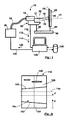
- Figure 1 shows schematically a thermal spraying installation.
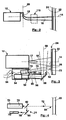
- Figure 2 illustrates a plasma arc thermal spray torch with injection transverse of the powdered material to be deposited, the jet being seen along the geometric axis referenced 56 in Figure 1.
- Figure 3 illustrates the on-board sensors with the CCD camera and the optical pyrometer.
- Figure 4 illustrates the optical pyrometer and its viewfinder.
- Figure 5 provides an example of a relational diagram of information in the database. data.
- Figure 6 illustrates the images processed by the computer.
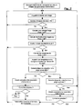
- FIG. 7 provides a synthetic example of an algorithm for ensuring the functions of the computer.
- the thermal projection instrument 10 comprises a thermal projection torch 12 with a geometric axis 14 projecting along this axis geometric 14 a jet 16 consisting of a flow of hot gas charged with droplets of the material to be projected in fusion: metal, metallic alloy, ceramic or cermet.
- Jet 16 is diverging and usually has the shape of a cone of revolution centered on the axis geometric 14.
- Sometimes a very bright flame 17 emerges from the torch 12 in the area of the top of the cone formed by the jet 16. In the case of plasma torches, this flame 17 can reach a temperature of 8000 ° K. Beyond this flame 17, the jet is also luminous but this luminosity does not come now basically just droplets of molten material.
- Jet 16 is normally centered on the geometric axis 14. Because of the high temperatures used in the torch 16 and despite the cooling devices integrated in these torches 16, the torches 16 degrade in particular by erosion during their operation, these degradations which can modify the characteristics of jet 16, deform jet 16 or do so deviate from the geometric axis 14.
- the torch 12 is of plasma arc type with transverse injection and includes an injector 18 with a perpendicular geometric axis 20 to the geometric axis of the torch 14, this injector 18 injecting into the jet 16 the material to spray powder using a so-called carrier gas, this injection taking place just at the outlet torch 12 in the area of the top of the cone formed by the jet 16, this injection takes place making transverse to jet 16 and causing deflection of jet 16 in the direction opposite the injector 18, the jet 16 then deviating normally from the geometric axis 14.
- the droplets of molten material projected by the jet 16 arrive at high speed and are crushed on the surface of the part 22 to be covered, in order to form there by solidification and adhesion deposit 24 sought.
- This deposit 24 is normally constituted by layers successive, the torch 12 repeatedly sweeping the surface of the part 22. will reference 26 the surface of the part 22 exposed at a given time to the jet 16.
- the torch can be held by hand, for example for repairing engineering structures metal. It is most often used on an installation 40 preferably robotized ensuring the relative maintenance, positioning and movement of the torch 12 and of part 22 to be treated.
- the installation 40 will advantageously include a robot arm 42 supporting the torch 12 as well as a fixed or pivoting workpiece holder 44 and maintaining the piece 22 in front of the torch 12.
- the projection instrument 10 includes on-board sensors 52 attached to the torch 12 so as to follow it in its movements during thermal projection, these on-board sensors 52 thus remaining in a constant relative position relative to the torch 12.
- the on-board sensors 52 consist first of all of a CCD camera 54 capable of providing digital images of the jet 16 taken transversely or even perpendicular to this jet 16.
- the camera 54 is positioned to provide an image of the jet 16 beyond the flame 17, that is to say downstream of this flame 17, so that the image of the jet 16 is not veiled by the light of the flame 17.
- the reference 56 will be geometrical axis of shooting of the camera 54.
- the camera 54 is arranged on the side of the torch 12 and aims the jet 16 by means of a shooting mirror 58 placed at 45 ° in front of the camera 54, this shooting mirror 58 deflecting at 90 ° the geometric axis of the CCD camera 56 and allowing this CCD camera 54 to see the jet 16.
- the camera must have sufficient resolution to perceive details of 0.5mm on the jet 16. This resolution is indeed necessary to detect and measure a deviation of the 0.5mm jet. In the case of aeronautical applications, this resolution should even be at least equal to 0.1mm in order to control the characteristics of the deposit with a sufficient precision.
- the camera has a CCD (Charge Coupled) matrix Device) of 640 x 480 pixels with an exposure time ranging from 1/30 second to 1/2000 second to observe very different light intensity jets with precision sufficient and without saturation of the pixels of the matrix.
- CCD camera sensitivity can be limited to the visible spectrum. A black and white camera is sufficient but you can also use a color camera. Such a camera is commonly marketed at low cost. It suffices that it has sufficient resistance to the heat given off during of thermal projection.
- the camera 54 is positioned to see the jet 16 along a geometric axis 56 substantially orthogonal to the geometric axis 20 of the injector 18, this position allowing to better visualize the deflection of jet 16 caused by this mode injection, this position therefore making it possible to more effectively control the jet deflection 16.
- the on-board sensors 52 also consist of an optical pyrometer 70 with a geometric axis 72 and remotely measuring the thermal radiation emitted by a so-called “measuring" surface 73, the measuring surface 73 being small on the geometric axis 72
- the pyrometer 70 is directive and it is capable of being pointed on the part 22 as close as possible to the projection area 26 but without however interfering with this projection area 26, that is to say that the measurement area 73 is close to or even adjacent to the projection area 26 but does not interfere with this projection area 26.
- the pyrometer 70 has a narrow field and it is positioned so that the field comes as close as possible to the jet 16 on the part 22 without however interfering with this jet 16.
- the very bright jet 16 remains outside the field of the pyrometer and in particular of the measurement zone 73 so that the pyrometer 70 receives the thermal radiation that of the deposit 24 but not the light radiation of the jet 16 which would be likely to distort the measurement of the temperature of the deposit.
- it advantageously includes a laser sight 74 projecting a light spot on the measurement area 73.
- the measurement of thermal radiation is usually done in the infrared, that is to say in the band of electromagnetic radiation ranging from 0.8 ⁇ m to 14 ⁇ m. In the particular case of plasma arc torches, this measurement will advantageously be made in the 8 ⁇ m - 14 ⁇ m band in order to have a stable, precise and inexpensive measurement.
- FIG. 4 An example of a viewfinder 74 is illustrated in FIG. 4.
- the viewfinder 74 projects a narrow laser beam 78 into the geometric axis 72 of the pyrometer 70.
- the viewfinder comprises a laser diode 76 placed on the side of the pyrometer 70, the laser diode 76 emitting a laser beam 78 at the front of the pyrometer 70 parallel to its geometric axis 72, the laser beam 78 being brought back into the geometric axis of the pyrometer 72 by a conventional set of two mirrors 80 and 82, the second mirror 82 being semi-reflecting and positioned on the geometric axis of the pyrometer 72.
- the adjustment of the viewfinder does not depend on the distance between the pyrometer 70 and the surface of the part whose temperature must be measured. It will be noted that the pyrometer 70 gives an exact measurement of the temperature only for perfect black bodies.
- the on-board sensors 52 are arranged at inside a closed enclosure 90 which protects them against external agents, this enclosure 90, however, comprising openings 92 allowing the camera 54 to see the jet 16 and with the pyrometer 70 to see the surface of the part 22, this enclosure 90 comprising a pressurized air supply 94, this pressurized air exiting by the openings 92 and obstructing the penetration of dust and droplets in the enclosure during the operation of the torch 12, this dust and droplets being likely to be deposited on the sensors 52 and in particular to foul the optical components.
- the thermal projection instrument 10 also includes a computer 100 connected by connection 110 to the sensors on-board 52, that is to the camera 54 and to the pyrometer 70.
- computer 100 is capable of receiving digital images 112 in real time from camera 54 as well as temperature readings 114 from pyrometer 70.
- the computer 100 is also connected by connection 120 to the cabinet command 30.
- the computer 100 is capable of transmit the power parameters to the control cabinet 30 in real time.
- this connection 120 also, the computer is likely to receive in real time power supply parameters of the control cabinet 30, for example the voltage V of the arc in the case of a plasma torch.
- real time is meant the value information to be applied upon receipt or the current value of the information that will be transmitted.
- Computer 100 can be a commonly used microcomputer sold equipped with appropriate connection means to be able to be connected to connections 110 and 120 respectively to sensors 52 and to the control cabinet 30, this computer 100 must also have sufficient power to be able to perform treatments at the appropriate frequency.
- the computer 100 also includes a base 130 containing the information necessary for controlling and steering the thermal spraying.
- the information is grouped into models, each model providing the information required to manage a deposit operation by thermal spraying with a torch, a deposition composition and specified deposit characteristics.
- the maximum light intensity of the jet l max is the maximum luminance of the jet 16, this maximum luminance of the jet usually being in the center of the jet 16 seen laterally from the outside and downstream of any flame 17 coming out of the torch 12.
- Luminance is a physical quantity expressable in watts per square meter and per steradian (w / m 2 / sr).
- the maximum light level of the pixels of the dot image 112 given by the matrix of the CCD camera 54 will be taken. This light level is common to known image standards such as bitmap, GIF, PSD, etc. It is usually coded on eight bits and consequently ranges from zero to 255.
- the CCD camera 54 used provides color images, that is to say in red-green-blue additive tri-color, we can simply take, but this is not compulsory, the maximum light level of the color green, this green color being the closest to the behavior of a CCD camera in black and white.
- the position of the jet P is the position of the jet relative to the geometric axis 14 of the torch 12.
- P will advantageously be the average of the distribution of the luminance of the jet also across the width of the jet 16a on image 112, for example and as previously along a line of pixels 154 perpendicular to position 14a on image 112 of the geometrical axis of torch 14.
- this veil and these light spots 156 being capable of distorting in a non-repetitive manner the estimates of the characteristics of the jet, we will advantageously take into account only the pixels whose light level is higher than a threshold value called "background noise level".
- This threshold value is easily determined by a separate analysis of a few test images. In practice, it is equal to 4 or 5 on the scale of the light levels ranging from 0 to 255 on the images 112.
- the temperature of the deposit T is the temperature measured by the pyrometer 70 and corrected by depending on the emissivity of the deposit.
- the CCD camera must have sufficient resolution to measure the width of the jet L and its position P with a fidelity of 0.5mm in current applications and 0.1mm in aeronautical applications. This means that the measurements must be repetitive and that they can detect deviations of 0.5mm and 0.1mm respectively in the variations in the quantities measured.
- the camera used here has a 640x480 matrix pixels.
- Figure 6 provides a synthetic example of an algorithm for to perform these functions. It is synthetic because it only gives the general logic of the control and piloting of the operation of the torch, because fall under a programming obvious: either the estimation of the projection characteristics, the choice of the characteristics projection parameters and corresponding power parameters to be corrected as well as the calculation of this correction.
- the torch used is a plasma thermal projection torch with external injection and more precisely the F4MB model marketed by the company Switzerland whose name is Sulzer Metco.
- the torch is used within substantially common operating ranges so that the same equations can be used.
- the operation of the torch is only limited by the maximum dissipated power, ie 55kw. If we adopt a safety margin of 10kw, the torch will not be used beyond 45kw and the arc intensity l will be conditioned by the following formula: l ⁇ 45000N
- V being the voltage of the plasma arc expressed in volts and given to the computer 100 by the control cabinet 30 via the connection 120 between the control cabinet 30 and the computer 100.
- the minimum arc intensity as well as the normal operating ranges of the other supply parameters, namely Ar, H 2 and Ar carrier, correspond to the domains in which these equations are valid.
- the optimal ranges and the acceptable ranges, each expressed by a minimum value and a maximum value, of Imax and T are as follows: Projection characteristics Priority order Acceptable ranges min / max Optimal mini / max ranges l max [0, 255] 1 0/40 0/20 T (° C) 2 190/280 190/220
- the initial values of the power supply parameters and the normal operating ranges expressed in terms of minimum / maximum value are given by the following table: Power settings Initial values Maximum / minimum operating ranges No correction the) 450 360/540 ⁇ 10 Ar (L / min) 45 36/54 ⁇ 1 H2 (L / min) 15 12/18 ⁇ 0.5 Ar carrier (Umn) 2.5 2/3 ⁇ 0.1
- the deposit must have a hardness at least equal to 120Hv, this deposit being carried out with the torch and the composition of the aforementioned deposit.
- the optimal and acceptable ranges expressed in terms of minimum / maximum values, L and l max are as follows: Projection characteristics Priority order Acceptable ranges min / max Optimal mini / max ranges L (mm) 1 2 / 9.8 2/5 l max [0.255] 2 20/180 20/100
- the initial values of the power supply parameters and the normal operating ranges expressed in terms of minimum / maximum value are given by the following table: Power settings Initial values Minimum / maximum operating ranges No correction the) 450 360/540 ⁇ 10 Ar (L / min) 45 36/54 ⁇ 1 H2 (L / min) 15 12/18 ⁇ 0.5 Ar carrier (L / min) 2.5 2/3 ⁇ 0.1
- This third quantified example combines the two previous examples, the deposit having to have an oxide content at most equal to 2% and a hardness at least equal to 120Hv, this deposit being carried out with the torch and the composition of the deposit mentioned above.
- the optimal and acceptable ranges expressed in terms of minimum / maximum values, l max , L and T are as follows: Projection characteristics Priority order Acceptable ranges min / max Optimal mini / max ranges l max [0.255] 1 20/40 19/20 L (mm) 2 2 / 9.8 2/5 T (° C) 3 190/280 190/220
- the initial values of the power supply parameters and the normal operating ranges expressed in terms of minimum / maximum value are given by the following table: Power settings Initial values Minimum / maximum operating ranges No correction the) 450 360/540 10 Ar (L / min) 45 36/54 1 H2 (L / min) 15 12/18 0.5 Ar carrier (L / min) 2.5 2/3 0.1
- the residual stresses of the deposit must be in compression and limited to -400 MPa (megaPascals), this deposit being carried out with the torch and the composition of the aforementioned deposit.
- the optimal and acceptable ranges expressed in terms of minimum / maximum values, L and T are as follows: Projection characteristics Acceptable ranges min / max Optimal mini / max ranges T (° C) 280/360 ° C 280/300 ° C
- the initial values of the power supply parameters and the normal operating ranges expressed in terms of minimum / maximum value are given by the following table: Power settings Initial values Minimum / maximum operating ranges No correction the) 450 360/540 10 Ar (L / min) ??? 36/54 1 H2 (L / min) ??? 12/18 0.5 Ar carrier (L / min) ??? 2/3 0.1
- the optimal ranges and the acceptable ranges, expressed in terms of minimum / maximum values of P and l max are as follows: Projection characteristics Priority order Acceptable ranges min / max Optimal mini / max ranges P (mm) 1 -5 / 1.2 -5/1 I max [0, 255] 2 20/100 20/50
- the initial values of the power supply parameters and the normal operating ranges expressed in terms of minimum / maximum value are given by the following table: Power settings Initial values Minimum / maximum operating ranges No correction the) 650 520/780 10 Ar (L / min) 45 36/54 1 H2 (L / min) 120 96/144 0.5 Ar carrier (L / min) 2.3 1.8 / 2.8 0.1
- the invention makes it possible to simultaneously guarantee several deposit characteristics insofar as the ranges of projection characteristics established for each characteristic of the deposit. Since these ranges do not overlap, it must then enlarge them and accept a greater dispersion in some characteristics of the deposit.
- the invention can be easily implemented with a commercial microcomputer equipped with appropriate interfaces to collect measurements of the characteristics of projection and to transmit new values of the power parameters to the control cabinet.
- Other equivalent IT architectures are possible and do not depart from the scope of the invention.
- IT resources can be those of a workstation shared by several machines.
- the invention applies to any type of thermal spray torch since the measurements used for piloting are made on the effects of the torch, in the occurrence on the jet it produces and on the temperature of the deposit.
- the proposed database is the preferred form of implementation of the invention but is not essential. Indeed, a more primitive solution consisting in introducing each time into the computer the data necessary for a thermal projection operation is also conceivable.
- the example of an information system proposed is simple and makes it possible to organize the information necessary for a thermal spraying operation. More elaborate models limiting the repetition of information are also possible. Sometimes it may be necessary to relate the operating range, the correction step or the order of priority to the equation - power parameter relationship, but the examples offered here do not require it.
- the sensors must be able to follow the execution of the projection thermal.
- these sensors will advantageously attached to the torch but they can also follow the movements of the torch by other ways.
- the claims also cover the case of an installation in which the torch would be fixed and the part to be coated movable in front of the torch.
Abstract
Description
La projection thermique peut être utilisée dans différents buts : décoration, barrière thermique, protection contre l'oxydation ou la corrosion chimique, rechargement de matière, augmentation des caractéristiques mécaniques de la surface, notamment de sa résistance à l'abrasion, etc.
La matière projeté peut être un métal pur tel le molybdène ou le titane, un aliage métallique tel le NiCr, le NiAl, le NiCrAlY, une céramique telle le Cr2O3 ou le ZrO2, un carbure tel le WC ou le Cr3C2, ou un cermet tel le Cr3C2/NiCr.
Un tel instrument est remarquable en ce que :
Un tel instrument permet de maítriser la dureté du revêtement, car il a été constaté que cette dureté dépend fortement de la largeur L du jet.
Un tel instrument permet d'étendre le domaine de fonctionnement normal de la torche, car il a été constaté que le taux de criques dépend également de l'intensité maximale lmax du jet, mais à un moindre degré que la position P du jet. Ainsi, lorsqu'il n'est plus possible de corriger P sans faire sortir les paramètres d'alimentation de leurs plages de fonctionnement normal, la torche étant trop dégradée, l'instrument permet encore d'agir sur l'intensité maximale lmax du jet pour garantir un taux de crique accepté.
La caméra, le pyromètre et les moyens informatiques utilisés sont répandus dans le commerce et bon marché, ce qui résout ainsi le second problème.
Dans le cas d'une torche à arc plasma, les paramètres essentiels d'alimentation de la torche sont :
- le courant d'arc électrique l et la tension V qui en résulte;
- le débit de chaque gaz plasmagène tels l'hydrogène H2 et l'argon Ar, exprimé par exemple en litres par minute, les litres étant considérés à la pression atmosphérique;
- le débit de matière Dm, exprimé par exemple en grammes par minute;
- le débit de gaz porteur, exprimé par exemple également en litres par minute, ce gaz étant habituellement de l'argon et étant noté Arporteur,
Les capteurs embarqués 52 sont constitués d'abord par une caméra CCD 54 susceptible de fournir des images numériques du jet 16 prises transversalement voire perpendiculairement à ce jet 16. Lorsque le jet 16 présente à son début une flamme 17, la caméra 54 est positionnée pour fournir une image du jet 16 au delà de la flamme 17, c'est à dire en aval de cette flamme 17, afin que l'image du jet 16 ne soit pas voilée par la lumière de la flamme 17. On référencera 56 l'axe géométrique de prise de vue de la caméra 54. De préférence mais non obligatoirement, la caméra 54 est disposée sur le coté de la torche 12 et vise le jet 16 par l'intermédiaire d'un miroir de prise de vue 58 disposé à 45° devant la caméra 54, ce miroir de prise de vue 58 déviant à 90° l'axe géométrique de la caméra CCD 56 et permettant à cette caméra CCD 54 de voir le jet 16.
- Lissage des vibrations haute fréquence du jet obtenu par l'effet d'accumulation des charges dans les pixels de la matrice CCD, cette accumulation s'effectuant en proportion de la lumière qu'ils reçoivent, ce lissage évitant de fausser les mesures et d'introduire des instabilités dans le pilotage de la torche. En effet, les capteurs intègrent la lumière reçue pendant la durée de l'exposition, de sorte que les variations de la luminance du jet 16 provenant de ces vibrations sont divisées par le rapport d/t, d étant la durée de l'exposition et t étant la période des vibrations du jet. Dans un dispositif classique, il aurait fallu disposer des filtres électroniques passe-bas sur chacun des éléments photosensibles ce qui en augmenterait l'encombrement et en limiterait le nombre.
- Grande résolution sous un faible volume, soit quelques centimètres cubes.
- Dispositif bon marché et permettant de prendre et de transmettre les images à l'ordinateur par des moyens standards et couramment commercialisés.
La mesure du rayonnement thermique est faite habituellement dans l'infrarouge, c'est à dire dans la bande de radiations électromagnétiques allant de 0,8µm à 14µm. Dans le cas particulier des torches à arc plasma cette mesure sera avantageusement faite dans la bande 8µm - 14µm afin d'avoir une mesure stable, précise et à moindre coût. En effet, avec ce type de torche, il a été constaté qu'il se produit au voisinage du jet 16 une ionisation de la vapeur d'eau H2O et du gaz carbonique CO2 contenus dans l'air, cette ionisation provoquant une absorption du rayonnement infrarouge dans les bandes 0,8µm - 3,46µm et 4,78µm - 8µm pour la vapeur d'eau et dans la bande 4,2µm à 4,5µm pour le gaz carbonique. Il a été constaté que des mesures de température effectuées sans exclure ces bandes d'absorption sont instables et affectées de bruits de fond qui les rendent difficilement exploitables. Il est donc préférable d'effectuer la mesure dans la bande 8µm - 14µm, cette bande étant suffisamment large pour que l'on puisse équiper le pyromètre 70 d'un filtre peu coûteux. Il est également possible d'effectuer cette mesure dans les bandes 3,46µm - 4,2µm ou 4,5µm - 4,78µm, mais celles-ci sont étroites et il est alors nécessaire d'équiper le pyromètre 70 de filtres à bande étroite performants et donc coûteux.
Un exemple de viseur 74 est illustré à la figure 4. Le viseur 74 projète un faisceau laser étroit 78 dans l'axe géométrique 72 du pyromètre 70. Pour cela, le viseur comporte une diode laser 76 disposée sur le coté du pyromètre 70, la diode laser 76 émettant un rayon laser 78 à l'avant du pyromètre 70 parallèlement à son axe géométrique 72, le rayon laser 78 étant ramené dans l'axe géométrique du pyromètre 72 par un jeu classique de deux miroirs 80 et 82, le second miroir 82 étant semi-réfléchissant et positionné sur l'axe géométrique du pyromètre 72. Avec une telle disposition, le réglage du viseur ne dépend pas de la distance entre le pyromètre 70 et la surface de la pièce dont il faut mesurer la température.
On notera que le pyromètre 70 ne donne une mesure exacte de la température que pour les corps noirs parfaits. Dans la réalité, il faut tenir compte du coefficient d'émissivité E de la matière dont on mesure la température, ce coefficient d'émissivité E étant compris entre 0 et 1, la température réelle T étant liée à la température observée par le pyromètre Tobs par la relation suivante :
La température mesurée peut être ainsi calculée par des moyens analogiques ou numériques.
- le modèle de torche utilisé;
- la composition du dépôt à effectuer;
- les caractéristiques du dépôt à obtenir;
- coefficient d'émissivité pour calculer la température exacte à partir de la mesure donnée par le pyromètre;
- période d'acquisition des images de la caméra CCD;
- Nombre d'images par lot;
- Niveau du bruit de fond;
- Niveau seuil de stabilité du jet.
- lmax : luminosité maximale du jet;
- L : largeur du jet;
- P : position du jet;
- T : température du dépôt.
- un ordre de priorité;
- une plage dite "acceptable" définie par une valeur minimale et une valeur maximale;
- et une plage dite "optimale" définie également par une valeur minimale et une valeur maximale, la plage optimale étant bien évidemment incluse dans la plage acceptable de la caractéristique de projection correspondante.
- l : intensité d'arc;
- Ar : débit d'argon plasmagène;
- H2 : débit d'hydrogène plasmagène;
- Arporteur : débit d'argon porteur.
- une valeur initiale à transmettre à l'armoire de commande au démarrage d'une opération de projection thermique;
- un ordre de priorité par par défaut s'appliquant uniformément à ce paramètre d'alimentation pour toutes les caractéristiques de projection sur lesquelles il a une influence.
- une plage de fonctionnement normal de la torche, exprimée par une valeur minimale et une valeur maximale, cette plage pouvant également exprimer les limites de validité de l'équation,
- un pas de correction,
- caractéristique de projection
- = F(paramètre d'alimentation)
= K + ∑iCipi + ∑jkCjkPjPk
- K est une constante positive ou négative;
- Ci est un coefficient positif ou négatif associé au paramètre d'alimentation i;
- Pi est la valeur courante du paramètre d'alimentation i;
- Cjk est un coefficient positif ou négatif associé au produit de deux paramètres d'alimentation j et k.
Ces relations sont évidemment statistiques et établies par ailleurs par des recherches en laboratoire. Elles sont valables, avec une dispersion acceptable, seulement à l'intérieur d'une plage de valeur spécifiées de chaque paramètre d'alimentation. Ainsi, la plage dite "de fonctionnement normal" peut correspondre :
- soit à des limitations de la torche;
- soit à des limitation de la validité de l'équation correspondant à un degré de dépendance jugé acceptable entre la caractéristique de projection concernée et les paramètres d'alimentation dont elle dépend.
- L'ordre des équations donne l'ordre de priorité dans lequel les caractéristiques de projection doivent être corrigées.
- L'ordre des paramètres d'alimentation dans chaque équation donne l'ordre de priorité dans lequel il faut modifier les paramètres d'alimentation pour corriger la caractéristique de projection correspondante.
l = niveau lumineux des pixels dans le sens de la largeur du jet;
x = position du pixel;
P0 = position 14a de l'axe géométrique 14 sur l'image 112, cette position 14a étant facilement repérée en emboítant une tige dans la buse de la torche 12 et en prenant une image 112 de cette tige.
Il est en conséquence avantageux d'exploiter cette information supplémentaire et de déduire Imax, P et σ de l'estimation de la loi de Gauss G de la distribution des niveaux lumineux des pixels comme précédemment dans le sens de la largeur du jet 16a sur l'image 112, par exemple et comme précédemment le long d'une ligne de pixels 154 perpendiculaire à la position 14a sur l'image 112 de l'axe géométrique de la torche 14, cette estimation pouvant par exemple être faite par la méthode bien connue dite "des moindres carrés".
Afin de réduire l'influence des lumières parasites et reflets lumineux en tous genres autour de l'installation de projection thermique, ces lumières parasites étant susceptibles de provoquer sur les images 112 un voile 156 diffus de part et d'autres de l'image du jet 16a ainsi que des taches claires 158 provenant de reflets, ce voile et ces taches claires 156 étant susceptibles de fausser de façon non répétitive les estimation des caractéristiques du jet, on ne prendra avantageusement en compte que les pixels dont le niveau lumineux est supérieur à une valeur seuil appelée "niveau du bruit de fond". Cette valeur seuil est facilement déterminée par une analyse séparée de quelques images tests. En pratique, elle est égale à 4 ou 5 sur l'échelle des niveaux lumineux s'étendant de 0 à 255 sur les images 112.
- Donner à l'armoire de commande les valeurs initiales des paramètres d'alimentation au démarrage d'une opération de dépôt.
- Acquérir N fois par seconde des images 112 provenant de la caméra CCD et les regrouper en lots de N1 images, et acquérir à la fin de chaque lot d'images une mesure de la température 114 issue du pyromètre.
- Pour chaque image, calculer les caractéristiques du jet utilisées à partir de pixels de
l'image sélectionnés sur une ligne de pixels 154 transversale à l'image du jet 16a et
dont le niveau lumineux nl est supérieur à celui du bruit de fond.
- Si on appelle x le rang des pixels le long de la ligne de pixels 154, P0 la position
14a sur l'image 112 de l'axe géométrique de la torche 14, nl le niveau lumineux
des pixels et n le nombre de pixels, Imax, L et P peuvent être calculés par les
formules suivantes :
- Imax = maximum (nl)
- P = moyenne de x = ∑ x.nl/∑nl -P0
- L = 2 x écart type = 2σ = 2.racine carrée[∑ (x.nl)2/n - (P+P0)2 ]
- Imax, P et L seront de préférence déduit d'une loi de Gauss établie, par exemple, par la méthode bien connue dite "des moindres carrés" à partir de la distribution du niveau lumineux nl des pixels le long de la ligne de pixels, cette loi de Gauss étant de la forme : Imax.exp(-(x-(P+P0))2/σ2)/2π
- Si on appelle x le rang des pixels le long de la ligne de pixels 154, P0 la position
14a sur l'image 112 de l'axe géométrique de la torche 14, nl le niveau lumineux
des pixels et n le nombre de pixels, Imax, L et P peuvent être calculés par les
formules suivantes :
- Pour chaque lot : vérifier que le jet 16 est stabilisé en vérifiant que les écarts des caractéristiques du jet entre les images du lot sont au plus égal au niveau seuil de stabilité du jet.
- Pour chaque lot d'image se rapportant à un jet 16 réputé stabilisé :
- Calculer les caractéristiques de projection en moyennant les mesures de Imax, L, P et en corrigeant la température T en fonction de l'émissivité de la surface mesurée.
- Rechercher la caractéristique de projection la plus importante ayant dérivé en dehors de sa plage acceptable prédéfinie, et déterminer et transmettre à l'armoire de commande 30 le paramètre d'alimentation à corriger ainsi que sa nouvelle valeur, lesquels sont appropriés pour ramener la caractéristique de projection vers sa plage acceptable.
- Emettre un signal d'alarme et transmettre à l'armoire de commande un ordre d'arrêt lorsqu'il n'est pas possible de ramener une caractéristique de projection vers sa plage acceptable sans faire sortir tous les paramètre d'alimentation de leurs plages de fonctionnement normales prédéfinies.
- Lorsque toutes les caractéristiques de projection sont chacune dans leur plage acceptable : rechercher la caractéristique de projection la plus importante située en dehors de sa plage optimale prédéfinie, et déterminer et transmettre à l'armoire de commande le paramètre d'alimentation à corriger ainsi que sa nouvelle valeur, lesquels sont appropriés pour amener ce paramètre de projection vers sa plage optimale. Par mesure de simplicité, et bien que ce ne soit pas obligatoire, les caractéristiques de projection seront traitées avec les mêmes ordres de priorité.
- Fréquence d'acquisition des images = N = 100 / seconde
- Nombre d'images par lot = N1 = 10
- Niveau du bruit de fond = 5
- Niveau de stabilité du jet = 1%
- l est exprimé en Ampères.
- Les débits de gaz Ar, Arporteur et H2 sont exprimés en litres par minutes ramenés à la pression atmosphérique.
- Les paramètres d'alimentation ont les mêmes ordres de priorité dans chaque équation et sont ainsi pris dans l'ordre de priorité décroissante suivant : Ar, H2,l, Arporteur. Cette identité des ordres de priorité est lié seulement à cette torche et n'a pas valeur de règle générale.
L'intensité d'arc minimale ainsi que les plages de fonctionnement normale des autres paramètres d'alimentation, soit Ar, H2 et Arporteur correspondent aux domaines dans lesquels ces équations sont valables .
- Si Imax doit être réduit, on augmentera Ar d'une valeur égale à son pas puisque le coefficient de Ar dans cette équation est négatif et égal à -1,51175. Inversement, si Imax doit être augmenté, on réduira au contraire Ar d'une valeur égale à son pas.
- Si Ar arrive hors sa plage de fonctionnement normal et que Imax doit être réduit, on réduira alors H2 d'une valeur égale à son pas puisque le coefficient de H2 dans cette équation est positif et égal à +38,2083. Inversement, si Imax doit être augmenté, on augmentera H2 d'une valeur égale à son pas.
| Caractéristiques de projection | Ordre de priorité | Plages acceptables mini / maxi | Plages optimales mini / maxi |
| lmax[0, 255] | 1 | 0/40 | 0 / 20 |
| T (°C) | 2 | 190/280 | 190/220 |
| Paramètres d'alimentation | Valeurs initiales | Plages de fonctionnement maxi / mini | Pas de correction |
| l(A) | 450 | 360/540 | ±10 |
| Ar(L/mn) | 45 | 36/54 | ±1 |
| H2(L/mn) | 15 | 12/18 | ±0,5 |
| Arporteur (Umn) | 2,5 | 2 / 3 | ±0,1 |
| Caractéristiques de projection | Ordre de priorité | Plages acceptables mini / maxi | Plages optimales mini / maxi |
| L(mm) | 1 | 2/9,8 | 2/5 |
| lmax [0,255] | 2 | 20/180 | 20/100 |
| Paramètres d'alimentation | Valeurs initiales | Plages de fonctionnement mini / maxi | Pas de correction |
| l(A) | 450 | 360 / 540 | ±10 |
| Ar(L/mn) | 45 | 36/54 | ±1 |
| H2(L/mn) | 15 | 12/18 | ±0,5 |
| Arporteur (L/mn) | 2,5 | 2/3 | ±0,1 |
| Caractéristiques de projection | Ordre de priorité | Plages acceptables mini / maxi | Plages optimales mini / maxi |
| lmax[0,255] | 1 | 20/40 | 19/20 |
| L(mm) | 2 | 2/9,8 | 2/5 |
| T (°C) | 3 | 190/280 | 190/220 |
| Paramètres d'alimentation | Valeurs initiales | Plages de fonctionnement mini / maxi | Pas de correction |
| l(A) | 450 | 360/540 | 10 |
| Ar(L/mn) | 45 | 36/54 | 1 |
| H2(L/mn) | 15 | 12/18 | 0,5 |
| Arporteur (L/mn) | 2,5 | 2 / 3 | 0,1 |
| Caractéristiques de projection | Plages acceptables mini / maxi | Plages optimales mini / maxi |
| T (°C) | 280 / 360°C | 280 / 300°C |
| Paramètres d'alimentation | Valeurs initiales | Plages de fonctionnement mini / maxi | Pas de correction |
| l (A) | 450 | 360/540 | 10 |
| Ar(L/mn) | ??? | 36/54 | 1 |
| H2(L/mn) | ??? | 12 / 18 | 0,5 |
| Arporteur (L/mn) | ??? | 2/3 | 0,1 |
L'opérateur utilise ici le système d'équations suivant dans lequel P est prioritaire lmax, P ayant une influence prépondérante et lmax une influence secondaire:
| Caractéristiques de projection | Ordre de priorité | Plages acceptables mini / maxi | Plages optimales mini / maxi |
| P(mm) | 1 | -5/1,2 | -5/1 |
| Imax [0, 255] | 2 | 20 / 100 | 20 / 50 |
| Paramètres d'alimentation | Valeurs initiales | Plages de fonctionnement mini / maxi | Pas de correction |
| l(A) | 650 | 520/780 | 10 |
| Ar (L/mn) | 45 | 36/54 | 1 |
| H2 (L/mn) | 120 | 96/144 | 0,5 |
| Arporteur(L/mn) | 2,3 | 1,8/2,8 | 0,1 |
L'exemple de système d'information proposé est simple et permet d'organiser les informations nécessaires à une opération de projection thermique. Des modèles plus élaborés limitant les répétitions d'informations sont également envisageables.
Quelquefois, il peut être nécessaire de rattacher la plage de fonctionnement, le pas de correction ou l'ordre de priorité à la relation équation - paramètre d'alimentation, mais les exemples proposés ici ne l'exigent pas.
Claims (16)
- Instrument de projection thermique (10) comportant une torche (12) de projection thermique, la torche (12) comportant un axe géométrique (14), la torche (12) étant susceptible de projeter un jet (16) selon son axe géométrique (14), le jet (16) étant constitué d'un flux de gaz à température élevée chargé de particules en fusion du matériau à projeter, l'instrument (10) comportant une armoire de commande (30) alimentant en ingrédients la torche (12) en appliquant les paramètres d'alimentation (122) qui lui sont communiqués, l'instrument (10) comportant un ordinateur (100) communiquant à l'armoire de commande (30) les paramètres d'alimentation (122) par l'intermédiaire d'une connexion armoire - ordinateur (120), l'instrument (10) comportant des capteurs (52) aptes à suivre les déplacements de la torche (12), les capteurs (52) étant susceptible de transmettre à l'ordinateur (100) des information (112,114) sur le fonctionnement de la torche (12), cette transmission s'effectuant par l'intermédiaire de la connexion capteurs - ordinateur (110), caractérisé en ce que :a. l'ordinateur (100) comporte un logiciel pour analyser en temps réel les informations (112,114), pour en déduire de façon répétitive la mesure d'au moins une caractéristique dite "de projection", pour repérer lorsque cette mesure est stabilisée, pour "traiter" cette caractéristique de projection, c'est à dire pour calculer et pour transmettre à l'armoire de commande (30) une nouvelle valeur de paramètre d'alimentation (122) lorsque la valeur mesurée de la caractéristique de projection est en dehors d'une plage de valeurs préétablie dite "acceptable" propre à la caractéristique de projection traitée, cette nouvelle valeur du paramètre d'alimentation étant appropriée pour rapprocher la caractéristique de projection vers sa plage acceptable.b. les capteurs (52) comportent une caméra (54) susceptible de fournir périodiquement à l'ordinateur (100) des informations (112,114) sous la forme d'images (112) numériques du jet (16) vu de profil sur une partie de sa longueur,c. la caractéristique de projection mesurée sur les images (112) est la position P du jet (16), la caméra (54) étant susceptible d'observer le jet (16) avec une résolution au moins égale 0,5mmm, P étant, à une valeur constante Po près, la moyenne de la distribution de la luminance du jet (16) suivant une ligne géométrique (154) transversale au jet (16), afin de maítriser le taux de criques du revêtement (22).
- Instrument selon la revendication 1 caractérisé en ce que l'ordinateur (100) mesure et traite également la largeur L du jet (16), L constituant également une caractéristique de projection, un ordre de priorité étant défini dans le traitement des caractéristiques de projection, le traitement de la position P du jet restant le plus prioritaire, L étant proportionnel à l'écart type de la distribution de la luminance du jet (16) suivant une ligne géométrique (154) transversale au jet (16), afin de maítriser également a dureté du revêtement (22).
- Instrument selon la revendication 1 ou 2 caractérisé en ce que :d. les capteurs 52 comportent également un pyromètre optique (70) apte à mesurer à distance le rayonnement thermique à la surface d'une éventuelle pièce (22) à revêtir positionnée devant la torche (12), le pyromètre (70) ayant un champ étroit, le pyromètre étant positionné pour que le champ arrive au plus près du jet (16) sur la pièce (22) sans toutefois interférer avec ce jet (16), le pyromètre (70) étant également apte à transmettre périodiquement à l'ordinateur (100) la mesure de température par l'intermédiaire de la connexion capteurs - ordinateur (110), la mesure de température transmise à l'ordinateur étant référencée (114);e. l'ordinateur (100) est apte à corriger la mesure de température (114) en fonction du coefficient d'émissivité du revêtement (22), T constituant alors également une caractéristique de projection, l'ordinateur (100) étant apte à traiter les caractéristiques de projection avec un ordre de priorité, le traitement de la largeur L du jet étant le plus prioritaire, afin de maítriser les contraintes résiduelles du dépôt.
- Instrument selon l'une quelconque des revendications 1 à 3 caractérisé en ce que l'ordinateur (100) mesure et traite également l'intensité maximale lmax du jet (16), cette mesure lmax constituant alors également une caractéristique de projection, l'ordinateur (100) étant apte à traiter les caractéristiques de projection avec un ordre de priorité, le traitement de la largeur L du jet étant le plus prioritaire, le traitement de l'intensité maximale lmax du jet arrivant en priorité seconde, afin d'étendre le domaine de fonctionnement normal de la torche (12).
- Instrument selon l'une quelconque des revendications 1 à 4 caractérisé en ce que l'ordinateur est apte à émettre un signal d'alerte lorsqu'une caractéristique de projection est en dehors de sa plage acceptable et qu'il ne peut calculer une nouvelle valeur de paramètre d'alimentation sans faire sortir la valeur de ce paramètre d'alimentation en dehors d'une plage dite "de fonctionnement normal" préétablie pour ce paramètre d'alimentation.
- Instrument selon l'une quelconque des revendications 1 à 5 caractérisé en ce que l'opération de projection thermique est interrompue lorsqu'une caractéristique de projection est en dehors de sa plage acceptable et que l'ordinateur (100) ne peut calculer une nouvelle valeur de paramètre d'alimentation sans faire sortir la valeur de ce paramètre d'alimentation en dehors d'une plage dite "de fonctionnement normal" préétablie pour ce paramètre d'alimentation.
- Instrument selon l'une quelconque des revendications 1 à 6 caractérisé en ce que l'ordinateur (100) est apte : à identifier la situation selon laquelle toutes les caractéristiques de projection utilisées sont chacune dans leur plage acceptable préétablie, à calculer et à transmettre à l'armoire de commande (30) une nouvelle valeur de paramètre d'alimentation (122) lorsque la valeur mesurée de la caractéristique de projection est en dehors d'une plage de valeurs préétablie dite "optimale" propre à la caractéristique de projection traitée, cette plage optimale étant incluse dans la plage acceptable, cette nouvelle valeur du paramètre d'alimentation étant appropriée pour rapprocher la caractéristique de projection vers sa plage optimale.
- instrument selon l'une quelconque des revendications 1 à 7 caractérisée en ce que la caméra (52) comporte une matrice à accumulation de charge.
- Instrument selon l'une quelconque des revendications 1 à 8 caractérisé en ce que la caméra est apte à fournir des images du jet (112) avec une résolution au moins égale à 0,1mm.
- Instrument selon l'une quelconque des revendications 1 à 9, une flamme (17) émergeant de la torche (12) dans la zone du sommet du cône formé par le jet (16), caractérisé en ce que la caméra (54) est positionnée pour fournir des images (122) du jet (16) en aval de la flamme (17).
- Instrument selon l'une quelconque des revendications 1 à 10, la torche (12) comportant un injecteur (18) de matière à projeter en poudre, cette injection s'effectuant à la sortie de la torche (12) suivant un axe géométrique (20) sensiblement perpendiculaire à l'axe géométrique de la torche (14), caractérisé en ce que la caméra (54) est positionnée pour voir le jet (16) suivant un axe géométrique (56) sensiblement orthogonal à l'axe géométrique (20) de l'injecteur (18).
- Instrument selon l'une quelconque des revendications 1 à 11 caractérisé en ce que la luminance du jet (16) prise en compte dans le traitement est le niveau lumineux des pixels des images (112).
- Instrument selon l'une quelconque des revendications 1 à 12 caractérisé en ce que l'ordinateur (100) est apte à ne prendre en compte que les pixels des images (112) dont le niveau lumineux est supérieur à une valeur préétablie.
- Instrument selon l'une quelconque des revendications 1 à 13 caractérisé en ce que la luminance maximale Imax, de la largeur L et de la position P du jet (16) traitées par l'ordinateur (100) sont des moyennes sur des images regroupées en lots.
- Instrument selon l'une quelconque des revendications 1 à 14 caractérisé en ce que l'une au moins des mesures effectuées sur les images (112), soit la luminance maximale lmax, la largeur L et la position P du jet(16), est déduite d'une loi de gauss de la forme lmax.exp(-(x-(P+P0))2/σ2)/2π.
- Instrument selon la revendication 3 caractérisé en ce que le pyromètre 70 comporte un viseur à laser (74).
Applications Claiming Priority (3)
| Application Number | Priority Date | Filing Date | Title |
|---|---|---|---|
| FR0202525A FR2836620B1 (fr) | 2002-02-28 | 2002-02-28 | Instrument de projection thermique |
| FR0202525 | 2002-02-28 | ||
| FR0202523A FR2836618B1 (fr) | 2002-02-28 | 2002-02-28 | Instrument de projection thermique |
Publications (3)
| Publication Number | Publication Date |
|---|---|
| EP1340577A2 true EP1340577A2 (fr) | 2003-09-03 |
| EP1340577A3 EP1340577A3 (fr) | 2004-05-12 |
| EP1340577B1 EP1340577B1 (fr) | 2006-05-03 |
Family
ID=47264336
Family Applications (2)
| Application Number | Title | Priority Date | Filing Date |
|---|---|---|---|
| EP03290478A Expired - Lifetime EP1340580B1 (fr) | 2002-02-28 | 2003-02-28 | Instrument de projection thermique |
| EP03290475A Expired - Lifetime EP1340577B1 (fr) | 2002-02-28 | 2003-02-28 | Instrument de projection thermique |
Family Applications Before (1)
| Application Number | Title | Priority Date | Filing Date |
|---|---|---|---|
| EP03290478A Expired - Lifetime EP1340580B1 (fr) | 2002-02-28 | 2003-02-28 | Instrument de projection thermique |
Country Status (7)
| Country | Link |
|---|---|
| US (2) | US7323061B2 (fr) |
| EP (2) | EP1340580B1 (fr) |
| JP (1) | JP4202265B2 (fr) |
| CA (2) | CA2476633C (fr) |
| DE (2) | DE60304917T2 (fr) |
| FR (2) | FR2836620B1 (fr) |
| WO (2) | WO2003073804A2 (fr) |
Cited By (3)
| Publication number | Priority date | Publication date | Assignee | Title |
|---|---|---|---|---|
| EP1927404A2 (fr) * | 2006-11-28 | 2008-06-04 | ABB PATENT GmbH | Procédé de détermination de paramètres de pulvérisation pour la commande d'un appareil de revêtement utilisant un moyen de pulvérisation |
| EP2962766A1 (fr) * | 2014-06-30 | 2016-01-06 | ABB Technology AG | Système et procédé de détermination de temps morts relatifs aux composants pour l'application par pulvérisation robotisée de fluides visqueux |
| EP2674225A3 (fr) * | 2012-06-11 | 2017-04-05 | General Electric Company | Régulation de la position d'un robot en fonction de la position du jet pulvérisé afin d'optimiser la qualité, l'efficacité et la reproductibilité du revêtement |
Families Citing this family (13)
| Publication number | Priority date | Publication date | Assignee | Title |
|---|---|---|---|---|
| US7226510B2 (en) * | 2003-10-27 | 2007-06-05 | Fujifilm Corporation | Film forming apparatus |
| JP4664054B2 (ja) * | 2004-12-09 | 2011-04-06 | 富士フイルム株式会社 | 成膜装置 |
| FR2883574B1 (fr) * | 2005-03-23 | 2008-01-18 | Snecma Moteurs Sa | "procede de depot par projection thermique d'un revetement anti-usure" |
| FR2894599B1 (fr) * | 2005-12-13 | 2008-02-22 | Hmr Expert Sas Soc Par Actions | Methode et dispositif pour determiner et regler les parametres de projection thermique au cours d'un depot de revetement par projection thermique |
| KR100860473B1 (ko) * | 2007-04-18 | 2008-09-26 | 에스엔유 프리시젼 주식회사 | 플라즈마 모니터링장치 |
| US20110171396A1 (en) * | 2010-01-08 | 2011-07-14 | Valerian Pershin | Thermally sprayed metal coatings on wood or wood composite surfaces |
| JP5995411B2 (ja) * | 2011-04-28 | 2016-09-21 | キヤノン株式会社 | 半導体ウェハーの製造方法、レンズの製造方法およびミラーの製造方法 |
| DE102011114382A1 (de) * | 2011-09-23 | 2013-03-28 | Dürr Systems GmbH | Beschichtungsverfahren und Beschichtungseinrichtung mit einer Kompensation von Unsymmetrien des Sprühstrahls |
| EP3370885B1 (fr) | 2015-11-04 | 2020-12-30 | Nordson Corporation | Méthode et dispositif pour contrôler un jet de pulvérisation |
| DE102016206995A1 (de) * | 2016-04-25 | 2017-10-26 | Rehm Thermal Systems Gmbh | Vorrichtung und Verfahren zur Vermessung eines Lackstrahls zum Beschichten von Platinen |
| EP3466597A1 (fr) | 2017-10-05 | 2019-04-10 | Synova S.A. | Appareil d'usinage d'une pièce par faisceau laser |
| US11114286B2 (en) * | 2019-04-08 | 2021-09-07 | Applied Materials, Inc. | In-situ optical chamber surface and process sensor |
| IT202100024266A1 (it) * | 2021-09-21 | 2023-03-21 | Ger Elettr S R L | Apparato di controllo perfezionato per un impianto di spruzzatura |
Citations (1)
| Publication number | Priority date | Publication date | Assignee | Title |
|---|---|---|---|---|
| USRE36926E (en) * | 1994-10-31 | 2000-10-31 | United Technologies Corporation | Welding control using fuzzy logic analysis of video imaged puddle dimensions |
Family Cites Families (10)
| Publication number | Priority date | Publication date | Assignee | Title |
|---|---|---|---|---|
| US36926A (en) * | 1862-11-11 | Improvement in evaporators | ||
| JPH0318484A (ja) * | 1989-06-16 | 1991-01-28 | Daido Steel Co Ltd | 立体物造形方法およびそれに用いる装置 |
| EP0837305A1 (fr) * | 1996-10-21 | 1998-04-22 | Sulzer Metco AG | Méthode et assemblage pour contrÔler le processus de revêtement dans un dispositif de revêtement thermique |
| JPH10153554A (ja) * | 1996-11-22 | 1998-06-09 | Horiba Ltd | Icpによる形態別元素分析方法 |
| CA2241761C (fr) * | 1997-06-27 | 2007-03-06 | Omega Engineering, Inc. | Systeme de visee et methode pour mesurer la temperature |
| US6377400B1 (en) * | 1999-07-02 | 2002-04-23 | Milton Bernard Hollander | Laser sighting beam modification for measuring or treatment instrument |
| GB0013737D0 (en) * | 2000-06-07 | 2000-07-26 | Astrazeneca Ab | Novel compounds |
| US6640878B2 (en) * | 2001-04-18 | 2003-11-04 | Ford Motor Company | Automated spray form cell |
| ES2260458T3 (es) * | 2001-07-02 | 2006-11-01 | Akzo Nobel N.V. | Derivados de tetrahidroquinolina. |
| US6967304B2 (en) * | 2002-04-29 | 2005-11-22 | Cyber Materials Llc | Feedback enhanced plasma spray tool |
-
2002
- 2002-02-28 FR FR0202525A patent/FR2836620B1/fr not_active Expired - Lifetime
- 2002-02-28 FR FR0202523A patent/FR2836618B1/fr not_active Expired - Fee Related
-
2003
- 2003-02-28 CA CA2476633A patent/CA2476633C/fr not_active Expired - Lifetime
- 2003-02-28 CA CA2476498A patent/CA2476498C/fr not_active Expired - Lifetime
- 2003-02-28 JP JP2003572342A patent/JP4202265B2/ja not_active Expired - Lifetime
- 2003-02-28 WO PCT/FR2003/000650 patent/WO2003073804A2/fr active Application Filing
- 2003-02-28 US US10/505,786 patent/US7323061B2/en not_active Expired - Lifetime
- 2003-02-28 EP EP03290478A patent/EP1340580B1/fr not_active Expired - Lifetime
- 2003-02-28 EP EP03290475A patent/EP1340577B1/fr not_active Expired - Lifetime
- 2003-02-28 US US10/505,954 patent/US7323062B2/en not_active Expired - Lifetime
- 2003-02-28 DE DE60304917T patent/DE60304917T2/de not_active Expired - Lifetime
- 2003-02-28 WO PCT/FR2003/000647 patent/WO2003072290A2/fr active Application Filing
- 2003-02-28 DE DE60304914T patent/DE60304914T2/de not_active Expired - Lifetime
Patent Citations (1)
| Publication number | Priority date | Publication date | Assignee | Title |
|---|---|---|---|---|
| USRE36926E (en) * | 1994-10-31 | 2000-10-31 | United Technologies Corporation | Welding control using fuzzy logic analysis of video imaged puddle dimensions |
Non-Patent Citations (4)
| Title |
|---|
| CHEN ET AL.: "intelligent methodology for sensing, modeling and control of pulsed gtaw: part I - bead-on-plate welding" WELDING RESEARCH, juin 2000 (2000-06), pages 151s-163s, XP000954653 * |
| DOUMANIDIS ET AL.: "distributed-parameter control of the heat source trajectory in thermal materials processing" JOURNAL OF MANUFACTURING SCIENCE AND ENGINEERING, vol. 118, novembre 1996 (1996-11), pages 571-578, XP000635785 * |
| PATENT ABSTRACTS OF JAPAN vol. 015, no. 138 (M-1100), 8 avril 1991 (1991-04-08) & JP 03 018484 A (DAIDO STEEL CO LTD;OTHERS: 01), 28 janvier 1991 (1991-01-28) * |
| PATENT ABSTRACTS OF JAPAN vol. 1998, no. 11, 30 septembre 1998 (1998-09-30) & JP 10 153554 A (HORIBA LTD), 9 juin 1998 (1998-06-09) * |
Cited By (7)
| Publication number | Priority date | Publication date | Assignee | Title |
|---|---|---|---|---|
| EP1927404A2 (fr) * | 2006-11-28 | 2008-06-04 | ABB PATENT GmbH | Procédé de détermination de paramètres de pulvérisation pour la commande d'un appareil de revêtement utilisant un moyen de pulvérisation |
| EP1927404A3 (fr) * | 2006-11-28 | 2008-10-15 | ABB PATENT GmbH | Procédé de détermination de paramètres de pulvérisation pour la commande d'un appareil de revêtement utilisant un moyen de pulvérisation |
| EP2674225A3 (fr) * | 2012-06-11 | 2017-04-05 | General Electric Company | Régulation de la position d'un robot en fonction de la position du jet pulvérisé afin d'optimiser la qualité, l'efficacité et la reproductibilité du revêtement |
| US11745201B2 (en) | 2012-06-11 | 2023-09-05 | General Electric Company | Spray plume position feedback for robotic motion to optimize coating quality, efficiency, and repeatability |
| EP2962766A1 (fr) * | 2014-06-30 | 2016-01-06 | ABB Technology AG | Système et procédé de détermination de temps morts relatifs aux composants pour l'application par pulvérisation robotisée de fluides visqueux |
| CN105215991A (zh) * | 2014-06-30 | 2016-01-06 | Abb技术有限公司 | 为粘性流体喷涂应用确定构件相关的时延的系统和方法 |
| CN105215991B (zh) * | 2014-06-30 | 2019-05-07 | Abb瑞士股份有限公司 | 为粘性流体喷涂应用确定构件相关的时延的系统和方法 |
Also Published As
| Publication number | Publication date |
|---|---|
| CA2476498A1 (fr) | 2003-09-04 |
| WO2003072290A2 (fr) | 2003-09-04 |
| US20050115500A1 (en) | 2005-06-02 |
| WO2003072290A3 (fr) | 2004-05-06 |
| FR2836620B1 (fr) | 2004-04-16 |
| DE60304914T2 (de) | 2006-12-21 |
| EP1340580A3 (fr) | 2004-03-10 |
| DE60304917T2 (de) | 2006-12-21 |
| US7323061B2 (en) | 2008-01-29 |
| WO2003073804A2 (fr) | 2003-09-04 |
| JP4202265B2 (ja) | 2008-12-24 |
| US20050199603A1 (en) | 2005-09-15 |
| FR2836618A1 (fr) | 2003-08-29 |
| EP1340577A3 (fr) | 2004-05-12 |
| DE60304917D1 (de) | 2006-06-08 |
| CA2476633C (fr) | 2010-12-07 |
| EP1340577B1 (fr) | 2006-05-03 |
| DE60304914D1 (de) | 2006-06-08 |
| FR2836618B1 (fr) | 2004-04-16 |
| EP1340580A2 (fr) | 2003-09-03 |
| EP1340580B1 (fr) | 2006-05-03 |
| CA2476498C (fr) | 2011-01-04 |
| US7323062B2 (en) | 2008-01-29 |
| CA2476633A1 (fr) | 2003-09-04 |
| WO2003073804A3 (fr) | 2004-03-04 |
| FR2836620A1 (fr) | 2003-08-29 |
| JP2005519193A (ja) | 2005-06-30 |
Similar Documents
| Publication | Publication Date | Title |
|---|---|---|
| EP1340580B1 (fr) | Instrument de projection thermique | |
| EP1340579B1 (fr) | Instrument de projection thermique | |
| Chivel et al. | On-line temperature monitoring in selective laser sintering/melting | |
| CA2892848C (fr) | Procede de fabrication d'une piece par fusion de poudre, les particules de poudre arrivant froides dans le bain | |
| EP1340578B1 (fr) | Instrument de projection thermique | |
| EP2614363B1 (fr) | Dispositif de cartographie et d'analyse à haute résolution d'éléments dans des solides | |
| US20100140236A1 (en) | Laser machining system and method | |
| Sdvizhenskii et al. | Online laser-induced breakdown spectroscopy for metal-particle powder flow analysis during additive manufacturing | |
| Richter et al. | Real-time measurement of temperature and volume of the weld pool in wire-arc additive manufacturing | |
| Bartkowiak | Direct laser deposition process within spectrographic analysis in situ | |
| Zhang et al. | Anomaly detection in laser metal deposition with photodiode-based melt pool monitoring system | |
| JP4095556B2 (ja) | 溶射器 | |
| DE102004041671A1 (de) | Überwachung von Spritzprozessen | |
| Brandau et al. | Angular dependence of coaxial and quasi-coaxial monitoring systems for process radiation analysis in laser materials processing | |
| JP2005525464A (ja) | 溶射装置 | |
| Valdiande Gutiérrez et al. | Laser metal deposition on-line monitoring via plasma emission spectroscopy and spectral correlation techniques | |
| Siewert et al. | Innovative diagnostics for thermal plasma processes |
Legal Events
| Date | Code | Title | Description |
|---|---|---|---|
| PUAI | Public reference made under article 153(3) epc to a published international application that has entered the european phase |
Free format text: ORIGINAL CODE: 0009012 |
|
| 17P | Request for examination filed |
Effective date: 20030322 |
|
| AK | Designated contracting states |
Kind code of ref document: A2 Designated state(s): AT BE BG CH CY CZ DE DK EE ES FI FR GB GR HU IE IT LI LU MC NL PT SE SI SK TR |
|
| AX | Request for extension of the european patent |
Extension state: AL LT LV MK RO |
|
| PUAL | Search report despatched |
Free format text: ORIGINAL CODE: 0009013 |
|
| AK | Designated contracting states |
Kind code of ref document: A3 Designated state(s): AT BE BG CH CY CZ DE DK EE ES FI FR GB GR HU IE IT LI LU MC NL PT SE SI SK TR |
|
| AX | Request for extension of the european patent |
Extension state: AL LT LV MK RO |
|
| AKX | Designation fees paid |
Designated state(s): CH DE FR GB IT LI NL |
|
| GRAP | Despatch of communication of intention to grant a patent |
Free format text: ORIGINAL CODE: EPIDOSNIGR1 |
|
| GRAS | Grant fee paid |
Free format text: ORIGINAL CODE: EPIDOSNIGR3 |
|
| GRAA | (expected) grant |
Free format text: ORIGINAL CODE: 0009210 |
|
| AK | Designated contracting states |
Kind code of ref document: B1 Designated state(s): CH DE FR GB IT LI NL |
|
| PG25 | Lapsed in a contracting state [announced via postgrant information from national office to epo] |
Ref country code: IT Free format text: LAPSE BECAUSE OF FAILURE TO SUBMIT A TRANSLATION OF THE DESCRIPTION OR TO PAY THE FEE WITHIN THE PRESCRIBED TIME-LIMIT;WARNING: LAPSES OF ITALIAN PATENTS WITH EFFECTIVE DATE BEFORE 2007 MAY HAVE OCCURRED AT ANY TIME BEFORE 2007. THE CORRECT EFFECTIVE DATE MAY BE DIFFERENT FROM THE ONE RECORDED. Effective date: 20060503 |
|
| REG | Reference to a national code |
Ref country code: GB Ref legal event code: FG4D Free format text: NOT ENGLISH |
|
| REG | Reference to a national code |
Ref country code: CH Ref legal event code: EP Ref country code: CH Ref legal event code: NV Representative=s name: MICHELI & CIE INGENIEURS-CONSEILS |
|
| GBT | Gb: translation of ep patent filed (gb section 77(6)(a)/1977) |
Effective date: 20060504 |
|
| REF | Corresponds to: |
Ref document number: 60304914 Country of ref document: DE Date of ref document: 20060608 Kind code of ref document: P |
|
| PLBI | Opposition filed |
Free format text: ORIGINAL CODE: 0009260 |
|
| PLAX | Notice of opposition and request to file observation + time limit sent |
Free format text: ORIGINAL CODE: EPIDOSNOBS2 |
|
| 26 | Opposition filed |
Opponent name: LINDE AG Effective date: 20070201 |
|
| NLR1 | Nl: opposition has been filed with the epo |
Opponent name: LINDE AG |
|
| PLAF | Information modified related to communication of a notice of opposition and request to file observations + time limit |
Free format text: ORIGINAL CODE: EPIDOSCOBS2 |
|
| PLBB | Reply of patent proprietor to notice(s) of opposition received |
Free format text: ORIGINAL CODE: EPIDOSNOBS3 |
|
| PLAB | Opposition data, opponent's data or that of the opponent's representative modified |
Free format text: ORIGINAL CODE: 0009299OPPO |
|
| REG | Reference to a national code |
Ref country code: CH Ref legal event code: PUE Owner name: SNECMA Free format text: SNECMA SERVICES#2, BOULEVARD DU GENERAL MARTIAL VALIN#75015 PARIS (FR) -TRANSFER TO- SNECMA#2, BOULEVARD DU GENERAL MARTIAL VALIN#75015 PARIS (FR) |
|
| RAP2 | Party data changed (patent owner data changed or rights of a patent transferred) |
Owner name: SNECMA |
|
| PLCK | Communication despatched that opposition was rejected |
Free format text: ORIGINAL CODE: EPIDOSNREJ1 |
|
| NLT2 | Nl: modifications (of names), taken from the european patent patent bulletin |
Owner name: SNECMA Effective date: 20091104 |
|
| REG | Reference to a national code |
Ref country code: FR Ref legal event code: TP |
|
| APAH | Appeal reference modified |
Free format text: ORIGINAL CODE: EPIDOSCREFNO |
|
| APBM | Appeal reference recorded |
Free format text: ORIGINAL CODE: EPIDOSNREFNO |
|
| APBP | Date of receipt of notice of appeal recorded |
Free format text: ORIGINAL CODE: EPIDOSNNOA2O |
|
| APBQ | Date of receipt of statement of grounds of appeal recorded |
Free format text: ORIGINAL CODE: EPIDOSNNOA3O |
|
| REG | Reference to a national code |
Ref country code: GB Ref legal event code: 732E Free format text: REGISTERED BETWEEN 20120419 AND 20120425 |
|
| REG | Reference to a national code |
Ref country code: DE Ref legal event code: R082 Ref document number: 60304914 Country of ref document: DE Representative=s name: MITSCHERLICH & PARTNER PATENT- UND RECHTSANWAE, DE |
|
| REG | Reference to a national code |
Ref country code: DE Ref legal event code: R082 Ref document number: 60304914 Country of ref document: DE Representative=s name: MITSCHERLICH & PARTNER PATENT- UND RECHTSANWAE, DE Effective date: 20121005 Ref country code: DE Ref legal event code: R081 Ref document number: 60304914 Country of ref document: DE Owner name: SNECMA, FR Free format text: FORMER OWNER: SNECMA SERVICES, PARIS, FR Effective date: 20121005 Ref country code: DE Ref legal event code: R082 Ref document number: 60304914 Country of ref document: DE Representative=s name: MITSCHERLICH, PATENT- UND RECHTSANWAELTE, PART, DE Effective date: 20121005 Ref country code: DE Ref legal event code: R082 Ref document number: 60304914 Country of ref document: DE Representative=s name: MITSCHERLICH, PATENT- UND RECHTSANWAELTE PARTM, DE Effective date: 20121005 |
|
| APBU | Appeal procedure closed |
Free format text: ORIGINAL CODE: EPIDOSNNOA9O |
|
| PLBN | Opposition rejected |
Free format text: ORIGINAL CODE: 0009273 |
|
| STAA | Information on the status of an ep patent application or granted ep patent |
Free format text: STATUS: OPPOSITION REJECTED |
|
| 27O | Opposition rejected |
Effective date: 20130910 |
|
| REG | Reference to a national code |
Ref country code: DE Ref legal event code: R100 Ref document number: 60304914 Country of ref document: DE Effective date: 20130910 |
|
| REG | Reference to a national code |
Ref country code: FR Ref legal event code: PLFP Year of fee payment: 14 |
|
| REG | Reference to a national code |
Ref country code: FR Ref legal event code: PLFP Year of fee payment: 15 |
|
| REG | Reference to a national code |
Ref country code: FR Ref legal event code: CD Owner name: SNECMA, FR Effective date: 20170713 |
|
| REG | Reference to a national code |
Ref country code: FR Ref legal event code: PLFP Year of fee payment: 16 |
|
| PGFP | Annual fee paid to national office [announced via postgrant information from national office to epo] |
Ref country code: GB Payment date: 20220124 Year of fee payment: 20 Ref country code: DE Payment date: 20220119 Year of fee payment: 20 Ref country code: CH Payment date: 20220120 Year of fee payment: 20 |
|
| PGFP | Annual fee paid to national office [announced via postgrant information from national office to epo] |
Ref country code: NL Payment date: 20220121 Year of fee payment: 20 Ref country code: IT Payment date: 20220119 Year of fee payment: 20 Ref country code: FR Payment date: 20220119 Year of fee payment: 20 |
|
| REG | Reference to a national code |
Ref country code: CH Ref legal event code: PL Ref country code: DE Ref legal event code: R071 Ref document number: 60304914 Country of ref document: DE |
|
| REG | Reference to a national code |
Ref country code: NL Ref legal event code: MK Effective date: 20230227 |
|
| REG | Reference to a national code |
Ref country code: GB Ref legal event code: PE20 Expiry date: 20230227 |
|
| PG25 | Lapsed in a contracting state [announced via postgrant information from national office to epo] |
Ref country code: GB Free format text: LAPSE BECAUSE OF EXPIRATION OF PROTECTION Effective date: 20230227 |