EP1340000B1 - Verfahren zum herstellen einer bremsscheibe und kernformwerkzeug - Google Patents
Verfahren zum herstellen einer bremsscheibe und kernformwerkzeug Download PDFInfo
- Publication number
- EP1340000B1 EP1340000B1 EP01985361A EP01985361A EP1340000B1 EP 1340000 B1 EP1340000 B1 EP 1340000B1 EP 01985361 A EP01985361 A EP 01985361A EP 01985361 A EP01985361 A EP 01985361A EP 1340000 B1 EP1340000 B1 EP 1340000B1
- Authority
- EP
- European Patent Office
- Prior art keywords
- core
- casting
- carrier part
- projection
- friction ring
- Prior art date
- Legal status (The legal status is an assumption and is not a legal conclusion. Google has not performed a legal analysis and makes no representation as to the accuracy of the status listed.)
- Expired - Lifetime
Links
- 238000004519 manufacturing process Methods 0.000 title claims abstract description 16
- 238000005266 casting Methods 0.000 claims abstract description 60
- 238000007789 sealing Methods 0.000 claims abstract description 46
- 239000004576 sand Substances 0.000 claims abstract description 26
- 238000000034 method Methods 0.000 claims abstract description 21
- 238000000465 moulding Methods 0.000 claims description 18
- 239000013013 elastic material Substances 0.000 claims description 4
- 239000011796 hollow space material Substances 0.000 claims 2
- 238000003825 pressing Methods 0.000 claims 1
- 239000000463 material Substances 0.000 description 9
- 239000011324 bead Substances 0.000 description 6
- 230000002093 peripheral effect Effects 0.000 description 6
- 230000035882 stress Effects 0.000 description 4
- 239000003110 molding sand Substances 0.000 description 3
- 230000015572 biosynthetic process Effects 0.000 description 2
- 230000002349 favourable effect Effects 0.000 description 2
- 238000002360 preparation method Methods 0.000 description 2
- 238000007711 solidification Methods 0.000 description 2
- 230000008023 solidification Effects 0.000 description 2
- 238000009736 wetting Methods 0.000 description 2
- 239000002131 composite material Substances 0.000 description 1
- 230000007797 corrosion Effects 0.000 description 1
- 238000005260 corrosion Methods 0.000 description 1
- 230000001747 exhibiting effect Effects 0.000 description 1
- 238000010438 heat treatment Methods 0.000 description 1
- 238000009434 installation Methods 0.000 description 1
- 238000005580 one pot reaction Methods 0.000 description 1
- 238000009417 prefabrication Methods 0.000 description 1
- 230000002028 premature Effects 0.000 description 1
- 230000008646 thermal stress Effects 0.000 description 1
- 230000007704 transition Effects 0.000 description 1
- 238000010792 warming Methods 0.000 description 1
Images




Classifications
-
- F—MECHANICAL ENGINEERING; LIGHTING; HEATING; WEAPONS; BLASTING
- F16—ENGINEERING ELEMENTS AND UNITS; GENERAL MEASURES FOR PRODUCING AND MAINTAINING EFFECTIVE FUNCTIONING OF MACHINES OR INSTALLATIONS; THERMAL INSULATION IN GENERAL
- F16D—COUPLINGS FOR TRANSMITTING ROTATION; CLUTCHES; BRAKES
- F16D65/00—Parts or details
- F16D65/02—Braking members; Mounting thereof
- F16D65/12—Discs; Drums for disc brakes
- F16D65/123—Discs; Drums for disc brakes comprising an annular disc secured to a hub member; Discs characterised by means for mounting
-
- F—MECHANICAL ENGINEERING; LIGHTING; HEATING; WEAPONS; BLASTING
- F16—ENGINEERING ELEMENTS AND UNITS; GENERAL MEASURES FOR PRODUCING AND MAINTAINING EFFECTIVE FUNCTIONING OF MACHINES OR INSTALLATIONS; THERMAL INSULATION IN GENERAL
- F16D—COUPLINGS FOR TRANSMITTING ROTATION; CLUTCHES; BRAKES
- F16D65/00—Parts or details
- F16D65/02—Braking members; Mounting thereof
- F16D2065/13—Parts or details of discs or drums
- F16D2065/1304—Structure
- F16D2065/1328—Structure internal cavities, e.g. cooling channels
-
- F—MECHANICAL ENGINEERING; LIGHTING; HEATING; WEAPONS; BLASTING
- F16—ENGINEERING ELEMENTS AND UNITS; GENERAL MEASURES FOR PRODUCING AND MAINTAINING EFFECTIVE FUNCTIONING OF MACHINES OR INSTALLATIONS; THERMAL INSULATION IN GENERAL
- F16D—COUPLINGS FOR TRANSMITTING ROTATION; CLUTCHES; BRAKES
- F16D65/00—Parts or details
- F16D65/02—Braking members; Mounting thereof
- F16D2065/13—Parts or details of discs or drums
- F16D2065/134—Connection
- F16D2065/1344—Connection permanent, e.g. by casting
-
- F—MECHANICAL ENGINEERING; LIGHTING; HEATING; WEAPONS; BLASTING
- F16—ENGINEERING ELEMENTS AND UNITS; GENERAL MEASURES FOR PRODUCING AND MAINTAINING EFFECTIVE FUNCTIONING OF MACHINES OR INSTALLATIONS; THERMAL INSULATION IN GENERAL
- F16D—COUPLINGS FOR TRANSMITTING ROTATION; CLUTCHES; BRAKES
- F16D65/00—Parts or details
- F16D65/02—Braking members; Mounting thereof
- F16D2065/13—Parts or details of discs or drums
- F16D2065/134—Connection
- F16D2065/1356—Connection interlocking
-
- F—MECHANICAL ENGINEERING; LIGHTING; HEATING; WEAPONS; BLASTING
- F16—ENGINEERING ELEMENTS AND UNITS; GENERAL MEASURES FOR PRODUCING AND MAINTAINING EFFECTIVE FUNCTIONING OF MACHINES OR INSTALLATIONS; THERMAL INSULATION IN GENERAL
- F16D—COUPLINGS FOR TRANSMITTING ROTATION; CLUTCHES; BRAKES
- F16D65/00—Parts or details
- F16D65/02—Braking members; Mounting thereof
- F16D2065/13—Parts or details of discs or drums
- F16D2065/134—Connection
- F16D2065/1372—Connection outer circumference
-
- F—MECHANICAL ENGINEERING; LIGHTING; HEATING; WEAPONS; BLASTING
- F16—ENGINEERING ELEMENTS AND UNITS; GENERAL MEASURES FOR PRODUCING AND MAINTAINING EFFECTIVE FUNCTIONING OF MACHINES OR INSTALLATIONS; THERMAL INSULATION IN GENERAL
- F16D—COUPLINGS FOR TRANSMITTING ROTATION; CLUTCHES; BRAKES
- F16D2250/00—Manufacturing; Assembly
- F16D2250/0007—Casting
-
- F—MECHANICAL ENGINEERING; LIGHTING; HEATING; WEAPONS; BLASTING
- F16—ENGINEERING ELEMENTS AND UNITS; GENERAL MEASURES FOR PRODUCING AND MAINTAINING EFFECTIVE FUNCTIONING OF MACHINES OR INSTALLATIONS; THERMAL INSULATION IN GENERAL
- F16D—COUPLINGS FOR TRANSMITTING ROTATION; CLUTCHES; BRAKES
- F16D2250/00—Manufacturing; Assembly
- F16D2250/0007—Casting
- F16D2250/0015—Casting around inserts
Definitions
- the invention relates to a method for producing a a carrier part and a friction ring Brake disc and a core mold, which in the course the production of such a brake disc used becomes.
- the carrier part Used in brake discs of the type in question the carrier part as a fastening for the Friction ring.
- the wheel hub on the support part attached to a vehicle wheel.
- the Carrier part to be cup-shaped, so that directly fastened on its front side the hub of the wheel and the brake disc on a bearing on the vehicle axle can be deferred.
- the carrier part also form the hub in which the respective Wheel bearing is arranged.
- the wheel of the Vehicle usually has an intermediate flange with the Carrier part connected.
- Brake discs are high in practical use subjected to mechanical and thermal stresses. This is especially true when heavy commercial vehicles must be braked from higher speeds. In the process, the vehicle's own kinetic Energy for the most part in heat converted, which is dissipated via the brake disc. Especially in commercial vehicles, there is the problem that it due to excessive heating of the friction ring too Stress cracks can come.
- DE 199 31 140 A1 discloses a method for producing one of a cast friction ring and a cast one Pot existing brake disc known.
- the pot is in a previously poured cast friction ring, in its interior Peripheral surfaces pocket-like recesses formed are. The material of the pot penetrates into these pockets and fills them, so that a secure form closure is ensured between the pot and the friction ring.
- One Another example of pouring a pot in one prefabricated friction ring is disclosed in EP 0 933 551 A1 given.
- the object of the invention is, starting from the above-explained prior art To provide a method of manufacturing brake disks with the continue in terms of their function optimized brake discs with at different times Cast molded part and friction ring can be produced.
- a core mold is to be specified, which in a special way for the implementation of the inventive method is suitable.
- Another advantage of the procedure according to the invention is that the shape of the projections easily the loads resulting from practical use can be adapted. Unlike the prior art, in which the material of the respective molded element flows into pockets of each prefabricated element, If necessary, more complex features of the Projections, such as narrow radii, rounding or Undercuts with a high dimensional accuracy in the course the prefabrication are generated. This can be done while pouring of casting material in pocket-like recess of each prefabricated element can not be accomplished.
- the invention thus makes it possible to brake discs in which in a simple way the friction ring and the support member so positively connected to each other are that the ring when heated in the radial Direction to expand freely. That way is the Danger of the formation of stress cracks in the friction ring a minimum reduced.
- the long life thus achieved It makes brake discs according to the invention possible to form the carrier part as a hub, which over a maintenance-free bearing stored directly on an axle is.
- As the life of the brake disc at least is equal to that of the camp is in such a Arrangement disassembly of the disc during the Duration of use of the bearing is not required, so that the during installation of the bearing specified optimum position of the Camp despite the directly associated with him Brake disc does not need to be changed.
- the prefabricated component is concerned preferably also to a casting. Since it at Casting of casting material to a prefabricated casting to no cohesive connection between the Materials can come so easily as pure as possible a positive connection between them connected parts are generated.
- the sealing of the projection can take place in that before molding the casting core to the projection Sealing element is attached, which is the surface of the End section opposite to the core sand of the casting core shields.
- This sealing element for example, so on be adapted to the shape of the end portion to be sealed, that in the sealing position the projection completely surrounds.
- the sealing element is advantageously formed so that it after the shooting of the G fauxkerns can be easily removed.
- the Sealing element is part of the core mold. On This way, the sealing element or its parts with the opening of the mold are removed from the carrier part.
- the sealing element preferably consists of an elastic material. Especially when using such an elastic material is easy possible to seal the free end portion of the To perform projection so that they under one on the Sealing element acting pressure force takes place. By the Applying such a compressive force becomes safety the sealing of the end portion improved.
- the carrier part regularly distributed around its circumference and radially from it having protruding projections. Because of the larger ones Number and the uniform arrangement of the tabs can the forces generated during braking easier to be absorbed by the support part. The same applies in the case of casting a support member to a with Tabs then provide friction ring when the friction ring regularly distributed over its inner surface and radially has protrusions protruding from it.
- a clean conclusion of only a part of the measured in the axial direction length of the support member extending casting core can thereby accomplish that the molding of the casting core under Seal the sand from the core not too wetting portion of the carrier part takes place.
- a core mold which with a Sub-case and a top box is equipped, where in the closed position, the composite upper and Lower boxes a mold for the casting core to be formed enclose.
- the invention is such Kernformwerkzeug characterized in that in the Hollow form a receptacle for a one of his Peripheral surface radially projecting projection exhibiting Carrier part of a brake disc is formed that at in the mold sitting support member between this and the outer wall of the mold at least in sections
- With sand fillable space is that one of the Hollow outgoing recess is present, which at in the mold sitting support part the free End portion of the projection of the support member receives, and that arranged in the region of the recess a seal is, which in closed position of upper and lower case seals the protruding into the receiving end portion opposite to the molding sand to be filled space of Cavity.
- the sealing element can by a in the recording Insert inserted, which is connected to the Shape of the end portion is adapted and this completely covers.
- the division level is between Upper and lower box preferably placed so that the Recess with her one section in the top box and with her other section in the sub-box is formed. This is particularly favorable when a sealing element is used, which is divided, wherein its one half in the top box assigned Section and its other half in the sub-box assigned portion of the recording sits.
- a clear limitation of the longitudinal extent of the Casting core can be accomplished in a simple manner be that a tangential to the circumference of the support part applicable seal is present, which is a Part of the cavity of the sand-fillable Room divides.
- the seals used in the tool according to the invention can also be moved from in the direction of the mold Sliding elements are worn. This is especially true for the tangential to the circumference of the support part adjustable sealing element. It can be both the Sealing the projection as well as for sealing a Section of the support member used sealing elements formed tubular and means venez horrbedeaufschlagung be expandable. alternative or in addition, the respective sealing element by worn by the upper and / or lower case Be formed sealing lips.
- Mold is particularly favorable design characterized in that the receptacle as a on the ground of the lower or upper box molded shoulder is formed, which in sitting on him support part this centered in the mold. That way is the with aligning the prefabricated part in the molding box associated expenses are reduced to a minimum.
- Core mold 1 is a prefabricated carrier part 2 used the hub or the pot one to be produced brake disc.
- the core mold has a top box 3 and a lower box 4, which together a cavity 5 enclose.
- Am by a wall of the lower box 4 formed bottom of the cavity 5 is centrally a Reception 6 in the form of a truncated cone-shaped shoulder formed, on which the carrier part 2 is attached.
- the outer diameter and the shape of the receptacle 6 are on the inner diameter and the shape of the interior of the Carrier part 2 adapted, in which the receptacle 6 engages. On This is the carrier part 2 through the receptacle 6 in the cavity 5 centered.
- each of the projections 10 engages in one Recess 11, starting from the cavity 5 and the Division level T between the top box 3 and the Lower box 4 with its upper portion 11a in the Upper box 3 and with its lower portion 11b in the Lower box 4 is formed.
- a sealing element 12a, 12b used, whose the respective projection 10 associated surface of the mold the relevant projection 10 is adapted.
- At her Cavity 5 associated end carry the sealing elements 12a, 12b additionally an annular cross-section Bead 13a, 13b, each close to its associated Surface of the respective projection 10 is present.
- the sealing elements 12a, 12b and their bead 13a and 13b consist of an elastic material. Your wall thickness is with respect to the shape of the recesses 11 and at in the recesses 11 engaging projections 10 in so oversized in this remaining space that the Sealing elements 12a, 12b and especially their respective bead 13a, 13b in the closed position of the core mold 1 below Pressure against the respective projection 10 are pressed. In this way, the carrier part 2 associated Foot section 10b safely opposite to the end the protrusions 10 extending free end portion 10 a sealed.
- elastic sealing elements 12a, 12b can be found in the area of the transition between the Recesses 11 to the cavity 5 not shown here Sealing lips are provided. It can for example, those associated with the sub-box Sealing elements on horizontally or vertically movable Be attached to sliders. Likewise, here too not shown, tube-like and when acted upon with internal pressure expanding sealing elements for Sealing the respective end portion 10b relative to the associated foot section 10a are used.
- the upper part of a mold for the annular disc-like, normal to the longitudinal axis of the Carrier element 2 arranged part 14 a of the Carrier element 2 to be formed casting core 14 is formed.
- the lower part of the mold is correspondingly in formed the lower box 4.
- the disc-shaped Part of the casting core 14 are when casting the friction ring to the support part 2, the fan channels of the friction ring educated.
- About openings 17 of the upper box 3 can Core sand in the area 5b of the cavity 5 and the so connected shape for the annular disc-like part 14 a be shot.
- a brake disc B is first in a green sand mold, not shown, the Carrier part 2 with the molded on it, finger-like in Cast radially protruding projections 10 (Fig. 4a). Subsequently, the prefabricated carrier part 2 used in the core molding apparatus 1 (Fig. 1a) and the casting core 14 by injecting molding sand in the Fillable areas of the mold 5 of Core molding device 1 integrally formed on the support member (Fig. 1b, Fig. 4b). It is by the sealing elements 12a, 12b or the respective bead 13a, 13b ensures that the End portions 10a of the projections 10 free of molding sand stay. With the opening of the core mold 1 those connected to the upper or lower box Sealing elements 12a, 12b with the respective beads 13a, 13b lifted from the end portions 10a of the projections 10, so that they are free for casting the friction ring R. lie.
- the mold must to do so only the mold for the friction ring and the seat for the carrier part 2 may be formed with the casting core 14.
Landscapes
- Engineering & Computer Science (AREA)
- General Engineering & Computer Science (AREA)
- Mechanical Engineering (AREA)
- Braking Arrangements (AREA)
Description
- Erzeugen des Trägerteils mit mindestens einem auf seinem Umfang angeordneten, radial abstehenden Vorsprung,
- Anformen eines den Vorsprung über einen dem Trägerteil zugeordneten Fußabschnitt umschließenden, aus Kernsand gebildeten Gießkerns an das Trägerteil unter Abdichtung eines freien Endabschnitts des Vorsprungs derart, daß dieser Endabschnitt nicht vom Sand des Gießkerns benetzt wird,
- Angießen des Reibrings an das mit dem Gießkern versehenen Trägerteil unter Umgießen des freien Endabschnitts des Vorsprungs.
- Erzeugen des Reibrings mit mindestens einem auf seiner Innenfläche angeordneten, radial vorstehenden Vorsprung,
- Anformen eines den Vorsprung über einen dem Reibring zugeordneten Fußabschnitt umschließenden, aus Kernsand gebildeten Gießkerns an den Reibring unter Abdichtung eines freien Endabschnitts des Vorsprungs derart, daß dieser Endabschnitt nicht vom Sand des Gießkerns benetzt wird,
- Angießen des Trägerteils an den mit dem Gießkern versehenen Reibring unter Umgießen des freien Endabschnitts des Vorsprungs.
- Fig. 1a
- einen Ausschnitt eines Kernformwerkzeugs in einer ersten Betriebsstellung in einem Längsschnitt,
- Fig. 1b
- das Kernformwerkzeug in einer zweiten Betriebsstellung in einer der Fig. 1 entsprechenden Ansicht,
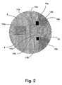
- Fig. 2
- einen Ausschnitt "A" der Fig. 1b in vergrößerter Darstellung,
- Fig. 3
- einen Ausschnitt eines Trägerteils mit angeformtem Gießkern in einer Ansicht von oben,
- Fig. 4a-4d
- das Trägerteil bei den im Zuge der Herstellung der Bremsscheibe durchlaufenen Arbeitsschritte in jeweils seitlicher Ansicht,
- Fig. 4a'
- das Trägerteil in einer Ansicht von oben.
- 1
- Kernformwerkzeug
- 2
- Trägerteil
- 3
- Oberkasten
- 4
- Unterkasten
- 5
- Hohlraum
- 5a
- dem Boden des Unterkastens 4 zugeordneter Bereich des Hohlraums 5
- 5b
- Bereich des Hohlraums 5, in dem der Ringteil 14b des Gießkerns 14 geformt wird
- 6
- Aufnahme
- 7
- Ausstoßer
- 8
- Rand des Trägerteils 2
- 9
- Deckel
- 10
- Vorsprünge
- 10a
- Endabschnitt der Vorsprünge
- 10b
- Fußabschnitt der Vorsprünge
- 11
- Ausnehmung
- 11a
- oberer Abschnitt der Ausnehmung 11
- 11b
- unterer Abschnitt der Ausnehmung 11
- 12a,12b
- Dichtelemente
- 13a,13b
- Wulst
- 14
- Gießkern
- 14a
- scheibenförmiger Teil des Gießkerns 14
- 14b
- Ringteil des Gießkerns 14
- 15
- Schieber
- 16
- Dichtung
- 17
- Öffnungen des Oberkastens 3
- B
- Bremsscheibe
- R
- Reibscheibe
- T
- Teilungsebene
Claims (17)
- Verfahren zum Herstellen einer ein Trägerteil (2) und einen Reibring (R) aufweisenden Bremsscheibe (B) umfassend die folgenden Arbeitsschritte:Erzeugen, insbesondere durch Gießen, des Trägerteils (2) mit mindestens einem auf seinem Umfang angeordneten, radial abstehenden Vorsprung (10),Anformen eines den Vorsprung (10) über einen dem Trägerteil (2) zugeordneten Fußabschnitt (10a) umschließenden, aus Kernsand gebildeten Gießkerns (14) an das Trägerteil (2) unter Abdichtung eines freien Endabschnitts (10a) des Vorsprungs (10) derart, daß dieser Endabschnitt (10a) nicht vom Sand des Gießkerns (14) benetzt wird,Angießen des Reibrings (R) an das mit dem Gießkern (14) versehenen Trägerteil (2) unter Umgießen des freien Endabschnitts (10a) des Vorsprungs (10).
- Verfahren zum Herstellen einer ein Trägerteil (2) und einen Reibring (R) aufweisenden Bremsscheibe (B) umfassend die folgenden Arbeitsschritte:Erzeugen, insbesondere Gießen, des Reibrings mit mindestens einem auf seiner Innenfläche angeordneten, radial vorstehenden Vorsprung,Anformen eines den Vorsprung über einen dem Reibring zugeordneten Fußabschnitt umschließenden, aus Kernsand gebildeten Gießkerns an den Reibring unter Abdichtung eines freien Endabschnitts des Vorsprungs derart, daß dieser Endabschnitt nicht vom Sand des Gießkerns benetzt wird,Angießen des Trägerteils an den mit dem Gießkern versehenen Reibring unter Umgießen des freien Endabschnitts des Vorsprungs.
- Verfahren nach Anspruch 1 oder 2, dadurch gekennzeichnet, daß vor dem Anformen des Gießkerns (14) an den Vorsprung (10) ein Dichtelement (12a,12b) angesetzt wird, welches die Oberfläche des Endabschnitts (10a) gegenüber dem Kernsand des Gießkerns (14) abschirmt.
- Verfahren nach Anspruch 3, dadurch gekennzeichnet, daß das Dichtelement (12a,12b) in der Abdichtstellung den Endabschnitt (10a) des Vorsprungs (10) vollständig umgibt.
- Verfahren nach einem der Ansprüche 3 oder 4, dadurch gekennzeichnet, daß das Dichtelement (12a,12b) aus einem elastischen Material besteht.
- Verfahren nach einem Ansprüche 3 bis 5, dadurch gekennzeichnet, daß die Abdichtung des freien Endabschnitts (10a) des Vorsprungs (10) unter einer auf das Dichtelement (12a,12b) wirkenden Druckkraft erfolgt.
- Verfahren nach Anspruch 1, dadurch gekennzeichnet, daß das Trägerteil (2) regelmäßig um seinen Umfang verteilte und radial von ihm abstehende Vorsprünge (10) aufweist.
- Verfahren nach Anspruch 2, dadurch gekennzeichnet, daß der Reibring (R) regelmäßig über seine Innenfläche verteilte und radial von dieser vorstehende Vorsprünge aufweist.
- Verfahren nach einem der voranstehenden Ansprüche, dadurch gekennzeichnet, daß der Gießkern (14) sich nur über einen Teil der in Achsrichtung gemessenen Länge des Trägerteils (2) erstreckt und d a ß das Anformen des Gießkerns (14) unter Abdichtung des vom Sand des Gießkerns (14) nicht zu benetzenden Abschnitts des Trägerteils (2) erfolgt.
- Kernformwerkzeug mit einem Unterkasten (4) und einem Oberkasten (3), wobei in der Schließstellung die zusammengesetzten Ober- (3) und Unterkästen (4) eine Hohlform (5) für den zu formenden Gießkern (14) umschließen, dadurch dadurch gekennzeichnet,daß in der Hohlform (5) eine Aufnahme (6) für ein einen von seiner Umfangsfläche radial vorstehenden Vorsprung (10) aufweisendes Trägerteil (2) einer Bremsscheibe (B) ausgebildet ist,daß bei in der Hohlform sitzendem Trägerteil (2) zwischen diesem und der äußeren Wand der Hohlform (5) zumindest abschnittweise ein mit Sand ausfüllbarer Raum (5b) besteht,daß eine von der Hohlform (5) abgehende Ausnehmung (11) vorhanden ist, welche bei in der Hohlform (5) sitzendem Trägerteil (2) den freien Endabschnitt (10a) des Vorsprungs (10) des Trägerteils (2) aufnimmt, unddaß im Bereich der Ausnehmung (11) eine Dichtung angeordnet ist, welche in Schließstellung des Kernformwerkzeugs (1) den in die Aufnahme (11) ragenden Endabschnitt (10a) abdichtet gegenüber dem mit Kernsand zu befüllenden Raum (5b) des Hohlraums (5).
- Kernformwerkzeug nach Anspruch 10, dadurch gekennzeichnet, daß das Dichtelement (12a,12b) durch ein in die Aufnahme (11) eingesetztes Einsatzstück gebildet ist, welches an die Form des Endabschnitts (10a) angepaßt ist und dieses vollständig abdeckt.
- Kernformwerkzeug nach einem der Ansprüche 10 oder 11, dadurch gekennzeichnet, daß die Ausnehmung (11) mit ihrem oberen Abschnitt (11a) in den Oberkasten (3) und mit ihrem unteren Abschnitt (11b) in den Unterkasten (4) eingeformt ist.
- Kernformwerkzeug nach einem der Ansprüche 10 bis 12, dadurch gekennzeichnet, daß eine tangential an den Umfang des Trägerteils (2) anlegbare Dichtung (16) vorhanden ist, welche einen Abschnitt (5a) des Hohlraums (5) von dessen mit Sand befüllbaren Raumabschnitt (5b) abteilt.
- Kernformwerkzeug nach einem der Ansprüche 10 bis 13, dadurch gekennzeichnet, daß die Dichtung (16) von in Richtung der Hohlform (5) bewegbaren Schiebelementen (15) getragen sind.
- Kernformwerkzeug nach einem der Ansprüche 10 bis 14, dadurch gekennzeichnet, daß das Dichtelement (16) schlauchförmig ausgebildet und mittels Innendruckbeaufschlagung expandierbar ist.
- Kernformwerkzeug nach einem der Ansprüche 10 bis 15, dadurch gekennzeichnet, daß das Dichtelement (12a,12b) durch von dem Ober- und /oder Unterkasten getragene Dichtlippen gebildet ist.
- Kernformwerkzeug nach einem der Ansprüche 10 bis 16, dadurch gekennzeichnet, daß die Aufnahme (6) als ein am Boden des Unterkastens (4) angeformter Absatz ausgebildet ist, welcher bei auf ihm sitzenden Trägerteil (2) dieses in der Hohlform (5) zentriert.
Applications Claiming Priority (3)
| Application Number | Priority Date | Filing Date | Title |
|---|---|---|---|
| DE10060262 | 2000-12-05 | ||
| DE10060262A DE10060262C2 (de) | 2000-12-05 | 2000-12-05 | Verfahren zum Herstellen einer Bremsscheibe und Kernformwerkzeug |
| PCT/EP2001/014218 WO2002046638A1 (de) | 2000-12-05 | 2001-12-05 | Verfahren zum herstellen einer bremsscheibe und kernformwerkzeug |
Publications (2)
| Publication Number | Publication Date |
|---|---|
| EP1340000A1 EP1340000A1 (de) | 2003-09-03 |
| EP1340000B1 true EP1340000B1 (de) | 2005-06-08 |
Family
ID=7665762
Family Applications (1)
| Application Number | Title | Priority Date | Filing Date |
|---|---|---|---|
| EP01985361A Expired - Lifetime EP1340000B1 (de) | 2000-12-05 | 2001-12-05 | Verfahren zum herstellen einer bremsscheibe und kernformwerkzeug |
Country Status (8)
| Country | Link |
|---|---|
| US (1) | US7096920B2 (de) |
| EP (1) | EP1340000B1 (de) |
| AT (1) | ATE297510T1 (de) |
| AU (1) | AU2002234543A1 (de) |
| DE (2) | DE10060262C2 (de) |
| ES (1) | ES2243575T3 (de) |
| MX (1) | MXPA03005049A (de) |
| WO (1) | WO2002046638A1 (de) |
Families Citing this family (16)
| Publication number | Priority date | Publication date | Assignee | Title |
|---|---|---|---|---|
| US10203008B2 (en) | 2004-10-26 | 2019-02-12 | Freni Brembo S.P.A. | Disc for a disc brake |
| CN101052820B (zh) † | 2004-10-26 | 2010-05-26 | 福乐尼·乐姆宝公开有限公司 | 用于盘式制动器的盘及制造该盘的方法 |
| JP4439424B2 (ja) * | 2005-03-30 | 2010-03-24 | 本田技研工業株式会社 | 鋳造用砂中子の金型への装着方法及び鋳造用砂中子 |
| US7543691B2 (en) * | 2006-07-12 | 2009-06-09 | Delphi Technologies, Inc. | Brake rotor assembly |
| DE102007001567B4 (de) | 2007-01-10 | 2009-07-02 | Fritz Winter Eisengiesserei Gmbh & Co. Kg | Bremsscheibe für eine Scheibenbremse |
| DE102007013512A1 (de) * | 2007-03-21 | 2008-09-25 | Audi Ag | Bremsscheibe für eine Scheibenbremse eines Fahrzeugs sowie Verfahren zur Herstellung einer solchen Bremsscheibe |
| DE102011120541A1 (de) | 2011-12-08 | 2013-06-13 | Daimler Ag | Bremsscheibe, insbesondere für einen Kraftwagen, sowie Verfahren zum Herstellen einer Bremsscheibe |
| DE102015108755A1 (de) * | 2014-06-26 | 2015-12-31 | Ksm Castings Group Gmbh | Verfahren zur Bildung eines Kerns, der zur Ausbildung eines Hohlraums in einem durch Gießen hergestellten Gehäuse einer Hochdruckpumpe bestimmt ist |
| US10267370B2 (en) | 2016-02-09 | 2019-04-23 | Saf-Holland, Inc. | Disc brake rotor adapter |
| US10253833B2 (en) | 2017-06-30 | 2019-04-09 | Honda Motor Co., Ltd. | High performance disc brake rotor |
| DE102018218093A1 (de) * | 2018-10-23 | 2020-04-23 | Audi Ag | Innenbelüftete Bremsscheibe |
| US11187290B2 (en) | 2018-12-28 | 2021-11-30 | Honda Motor Co., Ltd. | Aluminum ceramic composite brake assembly |
| DE102019113487A1 (de) * | 2019-05-21 | 2020-11-26 | Erdrich Umformtechnik Gmbh | Bremsscheibe |
| US12090781B2 (en) * | 2019-08-06 | 2024-09-17 | Consolidated Metco, Inc. | Wheel hub with integrated circular brake element |
| DE102019125167A1 (de) * | 2019-09-18 | 2021-03-18 | Zf Active Safety Gmbh | Kernformwerkzeug und Verfahren zur Herstellung eines Sandkerns |
| US12571441B2 (en) | 2020-05-05 | 2026-03-10 | Consolidated Metco, Inc. | Commercial vehicle brake rotor |
Family Cites Families (5)
| Publication number | Priority date | Publication date | Assignee | Title |
|---|---|---|---|---|
| EP0077137B1 (de) | 1981-10-01 | 1987-04-22 | Automotive Products Public Limited Company | Verfahren zur Herstellung einer Bremsscheibe |
| DE3335807A1 (de) | 1983-10-01 | 1985-04-18 | Schwäbische Hüttenwerke GmbH, 7080 Aalen | Bremsscheibe und formkern zur herstellung einer solchen bremsscheibe |
| DE3920418A1 (de) * | 1989-06-22 | 1991-01-03 | Schwaebische Huettenwerke Gmbh | Bremsscheibe fuer scheibenbremsen |
| EP0933551B1 (de) * | 1998-02-02 | 2001-11-07 | ALUMINIUM RHEINFELDEN GmbH | Bremsscheibe |
| DE19931140A1 (de) * | 1998-07-29 | 2000-02-17 | Continental Teves Ag & Co Ohg | Bremsscheibe, insbesondere Verbundguß-Bremsscheibe |
-
2000
- 2000-12-05 DE DE10060262A patent/DE10060262C2/de not_active Expired - Fee Related
-
2001
- 2001-12-05 AT AT01985361T patent/ATE297510T1/de not_active IP Right Cessation
- 2001-12-05 US US10/450,306 patent/US7096920B2/en not_active Expired - Lifetime
- 2001-12-05 EP EP01985361A patent/EP1340000B1/de not_active Expired - Lifetime
- 2001-12-05 WO PCT/EP2001/014218 patent/WO2002046638A1/de not_active Ceased
- 2001-12-05 MX MXPA03005049A patent/MXPA03005049A/es active IP Right Grant
- 2001-12-05 AU AU2002234543A patent/AU2002234543A1/en not_active Abandoned
- 2001-12-05 ES ES01985361T patent/ES2243575T3/es not_active Expired - Lifetime
- 2001-12-05 DE DE50106478T patent/DE50106478D1/de not_active Expired - Lifetime
Also Published As
| Publication number | Publication date |
|---|---|
| DE50106478D1 (de) | 2005-07-14 |
| ATE297510T1 (de) | 2005-06-15 |
| WO2002046638A1 (de) | 2002-06-13 |
| US7096920B2 (en) | 2006-08-29 |
| DE10060262C2 (de) | 2002-10-24 |
| ES2243575T3 (es) | 2005-12-01 |
| MXPA03005049A (es) | 2003-10-15 |
| AU2002234543A1 (en) | 2002-06-18 |
| EP1340000A1 (de) | 2003-09-03 |
| US20040040803A1 (en) | 2004-03-04 |
| DE10060262A1 (de) | 2002-07-04 |
Similar Documents
| Publication | Publication Date | Title |
|---|---|---|
| DE10060262C2 (de) | Verfahren zum Herstellen einer Bremsscheibe und Kernformwerkzeug | |
| EP0143264B1 (de) | Bremsscheibe sowie Formkern und Verfahren zur Herstellung einer solchen Bremsscheibe. | |
| DE19505724A1 (de) | Aluminium-Bremsscheibe | |
| EP0033712B1 (de) | Vorrichtung zum Herstellen von Fahrzeugrädern | |
| DE1912415A1 (de) | Fahrzeug?ad und V?fahren zu seiner H?tellung | |
| DE102008040873A1 (de) | Verfahren zur Herstellung einer elektrischen Maschine sowie Elektrische Maschine für ein Hybridfahrzeug | |
| EP1360428B1 (de) | Spanlos geformter bremssattel und verfahren zur herstellung | |
| DE2442785B2 (de) | Verfahren zur herstellung einer einteiligen ringfelge oder eines ringfelgenteils | |
| DE3117162C2 (de) | "Verfahren zur paarweisen Herstellung von kunststoffumspritzten Laufringen für Wälzlager" | |
| DE3143156A1 (de) | "gegossenes fahrzeugrad" | |
| EP2100051B1 (de) | Bremsscheibe für eine scheibenbremse | |
| DE69609693T2 (de) | Kolbenringpositionierungsvorrichtung und Kolbenstranggiessverfahren unter Verwendung dieser Vorrichtung | |
| EP1636473B1 (de) | Kolben für einen verbrennungsmotor und giessverfahren zu dessen herstellung | |
| DE19853803C1 (de) | Vorrichtung und Verfahren für die Herstellung eines Motorblocks | |
| EP0848652B1 (de) | Verfahren und vorrichtung zum befüllen eines giesswerkzeugs mit einer metallschmelze | |
| EP3853974B1 (de) | Giessform zur herstellung von wendelförmigen gusskörpern | |
| DE69903587T4 (de) | Verfahren zur Herstellung einer O-Ring-Halterung in Gegenständen unter Verwendung verriegelbarer Formen und Vorrichtung dafür | |
| DE102009049315B4 (de) | Vorrichtung zum Herstellen eines Verbundgussteiles | |
| DE102014110903A1 (de) | Verfahren zur Herstellung eines Schiebemuffenrings | |
| EP0826442B1 (de) | Fahrzeugrad | |
| DE19726111C1 (de) | Verfahren zur gießtechnischen Herstellung einer Turbomaschinenschaufel | |
| WO2012071599A1 (de) | VERFAHREN ZUR HERSTELLUNG EINES GUSSRADS UND GIEßWERKZEUG | |
| DE10142980A1 (de) | Ringfeldhinterschnitt bei einem Kolben | |
| DE2846949A1 (de) | Form zur herstellung von luftreifen aus fluessigen oder pastosen materialien | |
| DE10114404C2 (de) | Formkörper (Kern) am Ringträger |
Legal Events
| Date | Code | Title | Description |
|---|---|---|---|
| PUAI | Public reference made under article 153(3) epc to a published international application that has entered the european phase |
Free format text: ORIGINAL CODE: 0009012 |
|
| 17P | Request for examination filed |
Effective date: 20030506 |
|
| AK | Designated contracting states |
Kind code of ref document: A1 Designated state(s): AT BE CH CY DE DK ES FI FR GB GR IE IT LI LU MC NL PT SE TR |
|
| AX | Request for extension of the european patent |
Extension state: AL LT LV MK RO SI |
|
| GRAP | Despatch of communication of intention to grant a patent |
Free format text: ORIGINAL CODE: EPIDOSNIGR1 |
|
| GRAS | Grant fee paid |
Free format text: ORIGINAL CODE: EPIDOSNIGR3 |
|
| GRAA | (expected) grant |
Free format text: ORIGINAL CODE: 0009210 |
|
| AK | Designated contracting states |
Kind code of ref document: B1 Designated state(s): AT BE CH CY DE DK ES FI FR GB GR IE IT LI LU MC NL PT SE TR |
|
| PG25 | Lapsed in a contracting state [announced via postgrant information from national office to epo] |
Ref country code: IE Free format text: LAPSE BECAUSE OF FAILURE TO SUBMIT A TRANSLATION OF THE DESCRIPTION OR TO PAY THE FEE WITHIN THE PRESCRIBED TIME-LIMIT Effective date: 20050608 Ref country code: FI Free format text: LAPSE BECAUSE OF FAILURE TO SUBMIT A TRANSLATION OF THE DESCRIPTION OR TO PAY THE FEE WITHIN THE PRESCRIBED TIME-LIMIT Effective date: 20050608 |
|
| REG | Reference to a national code |
Ref country code: GB Ref legal event code: FG4D Free format text: NOT ENGLISH |
|
| REG | Reference to a national code |
Ref country code: CH Ref legal event code: EP |
|
| REF | Corresponds to: |
Ref document number: 50106478 Country of ref document: DE Date of ref document: 20050714 Kind code of ref document: P |
|
| REG | Reference to a national code |
Ref country code: IE Ref legal event code: FG4D Free format text: LANGUAGE OF EP DOCUMENT: GERMAN |
|
| REG | Reference to a national code |
Ref country code: SE Ref legal event code: TRGR |
|
| PG25 | Lapsed in a contracting state [announced via postgrant information from national office to epo] |
Ref country code: GR Free format text: LAPSE BECAUSE OF FAILURE TO SUBMIT A TRANSLATION OF THE DESCRIPTION OR TO PAY THE FEE WITHIN THE PRESCRIBED TIME-LIMIT Effective date: 20050908 Ref country code: DK Free format text: LAPSE BECAUSE OF FAILURE TO SUBMIT A TRANSLATION OF THE DESCRIPTION OR TO PAY THE FEE WITHIN THE PRESCRIBED TIME-LIMIT Effective date: 20050908 |
|
| GBT | Gb: translation of ep patent filed (gb section 77(6)(a)/1977) |
Effective date: 20050917 |
|
| PG25 | Lapsed in a contracting state [announced via postgrant information from national office to epo] |
Ref country code: PT Free format text: LAPSE BECAUSE OF FAILURE TO SUBMIT A TRANSLATION OF THE DESCRIPTION OR TO PAY THE FEE WITHIN THE PRESCRIBED TIME-LIMIT Effective date: 20051114 |
|
| REG | Reference to a national code |
Ref country code: ES Ref legal event code: FG2A Ref document number: 2243575 Country of ref document: ES Kind code of ref document: T3 |
|
| PG25 | Lapsed in a contracting state [announced via postgrant information from national office to epo] |
Ref country code: AT Free format text: LAPSE BECAUSE OF NON-PAYMENT OF DUE FEES Effective date: 20051205 Ref country code: CY Free format text: LAPSE BECAUSE OF FAILURE TO SUBMIT A TRANSLATION OF THE DESCRIPTION OR TO PAY THE FEE WITHIN THE PRESCRIBED TIME-LIMIT Effective date: 20051205 |
|
| PG25 | Lapsed in a contracting state [announced via postgrant information from national office to epo] |
Ref country code: MC Free format text: LAPSE BECAUSE OF NON-PAYMENT OF DUE FEES Effective date: 20051231 Ref country code: LU Free format text: LAPSE BECAUSE OF NON-PAYMENT OF DUE FEES Effective date: 20051231 Ref country code: LI Free format text: LAPSE BECAUSE OF NON-PAYMENT OF DUE FEES Effective date: 20051231 Ref country code: CH Free format text: LAPSE BECAUSE OF NON-PAYMENT OF DUE FEES Effective date: 20051231 |
|
| REG | Reference to a national code |
Ref country code: IE Ref legal event code: FD4D |
|
| ET | Fr: translation filed | ||
| PLBE | No opposition filed within time limit |
Free format text: ORIGINAL CODE: 0009261 |
|
| STAA | Information on the status of an ep patent application or granted ep patent |
Free format text: STATUS: NO OPPOSITION FILED WITHIN TIME LIMIT |
|
| 26N | No opposition filed |
Effective date: 20060309 |
|
| REG | Reference to a national code |
Ref country code: CH Ref legal event code: PL |
|
| REG | Reference to a national code |
Ref country code: FR Ref legal event code: PLFP Year of fee payment: 15 |
|
| REG | Reference to a national code |
Ref country code: FR Ref legal event code: PLFP Year of fee payment: 16 |
|
| REG | Reference to a national code |
Ref country code: FR Ref legal event code: PLFP Year of fee payment: 17 |
|
| PGFP | Annual fee paid to national office [announced via postgrant information from national office to epo] |
Ref country code: TR Payment date: 20201130 Year of fee payment: 20 |
|
| PGFP | Annual fee paid to national office [announced via postgrant information from national office to epo] |
Ref country code: SE Payment date: 20201221 Year of fee payment: 20 Ref country code: FR Payment date: 20201218 Year of fee payment: 20 Ref country code: DE Payment date: 20201216 Year of fee payment: 20 Ref country code: GB Payment date: 20201222 Year of fee payment: 20 |
|
| PGFP | Annual fee paid to national office [announced via postgrant information from national office to epo] |
Ref country code: BE Payment date: 20201217 Year of fee payment: 20 |
|
| PGFP | Annual fee paid to national office [announced via postgrant information from national office to epo] |
Ref country code: NL Payment date: 20201217 Year of fee payment: 20 |
|
| PGFP | Annual fee paid to national office [announced via postgrant information from national office to epo] |
Ref country code: ES Payment date: 20210122 Year of fee payment: 20 |
|
| PGFP | Annual fee paid to national office [announced via postgrant information from national office to epo] |
Ref country code: IT Payment date: 20201230 Year of fee payment: 20 |
|
| REG | Reference to a national code |
Ref country code: DE Ref legal event code: R071 Ref document number: 50106478 Country of ref document: DE |
|
| REG | Reference to a national code |
Ref country code: NL Ref legal event code: MK Effective date: 20211204 |
|
| REG | Reference to a national code |
Ref country code: GB Ref legal event code: PE20 Expiry date: 20211204 |
|
| REG | Reference to a national code |
Ref country code: BE Ref legal event code: MK Effective date: 20211205 |
|
| REG | Reference to a national code |
Ref country code: SE Ref legal event code: EUG |
|
| PG25 | Lapsed in a contracting state [announced via postgrant information from national office to epo] |
Ref country code: GB Free format text: LAPSE BECAUSE OF EXPIRATION OF PROTECTION Effective date: 20211204 |
|
| REG | Reference to a national code |
Ref country code: ES Ref legal event code: FD2A Effective date: 20220405 |
|
| PG25 | Lapsed in a contracting state [announced via postgrant information from national office to epo] |
Ref country code: ES Free format text: LAPSE BECAUSE OF EXPIRATION OF PROTECTION Effective date: 20211206 |