EP1339149B1 - Leitungsführungskanal - Google Patents
Leitungsführungskanal Download PDFInfo
- Publication number
- EP1339149B1 EP1339149B1 EP03002269A EP03002269A EP1339149B1 EP 1339149 B1 EP1339149 B1 EP 1339149B1 EP 03002269 A EP03002269 A EP 03002269A EP 03002269 A EP03002269 A EP 03002269A EP 1339149 B1 EP1339149 B1 EP 1339149B1
- Authority
- EP
- European Patent Office
- Prior art keywords
- bar
- strip
- trunking
- channel
- corner
- Prior art date
- Legal status (The legal status is an assumption and is not a legal conclusion. Google has not performed a legal analysis and makes no representation as to the accuracy of the status listed.)
- Expired - Lifetime
Links
Images

Classifications
-
- H—ELECTRICITY
- H02—GENERATION; CONVERSION OR DISTRIBUTION OF ELECTRIC POWER
- H02G—INSTALLATION OF ELECTRIC CABLES OR LINES, OR OF COMBINED OPTICAL AND ELECTRIC CABLES OR LINES
- H02G3/00—Installations of electric cables or lines or protective tubing therefor in or on buildings, equivalent structures or vehicles
- H02G3/02—Details
- H02G3/06—Joints for connecting lengths of protective tubing or channels, to each other or to casings, e.g. to distribution boxes; Ensuring electrical continuity in the joint
- H02G3/0608—Joints for connecting non cylindrical conduits, e.g. channels
Definitions
- the invention relates to cable trunking according to the preamble of claim 1.
- Cable trunking has been produced, distributed and assembled in large quantities worldwide for more than 100 years. They usually have a U or. C-shaped bottom with bottom, two side walls and lid holding profiles on the side walls and a lid which is releasably latched onto the lid holding profiles. Partitions in the interior of the trunking subdivide the cross section into mutually insulated chambers, for example for power lines and data lines.
- the partitions consist of a simple bar, which can either be made in one piece with the trunking base or suspended in retaining strips at the bottom of the channel. From the FR 22 08 220 A and the FR 26 10 769 A Routing channels are known, the partitions of two mutually spaced, parallel strips or lips are formed. The mutual distance is matched to the strength of the fastening nails or screws to be used, which are isolated in this way without additional effort against the high-voltage and low-voltage power lines.
- a connecting device which consists of a compensating piece which can be pushed onto one end of a cable duct. As a result, different channel sections can be connected to each other.
- the present invention is therefore an object of the invention to provide a cable trunking of the type mentioned above, the chambers of which can be sealed against each other even with butted corners of any kind.
- the present invention uses a simple bar, which can be inserted at the manufacturer between the two lips of the channel partition. During on-site installation, the installer only has to pull out the strips of the two butted channels so that they touch each other in the corner area. As a result, the mutual partitioning and insulation of the chambers for power lines and data lines is made. This solution is characterized by high flexibility and minimal costs.
- Another advantage of the strip according to the invention is that it can also be used as a coupling in the laying of the channels in a straight line, so that the channels are exactly aligned.
- the strip has an outgoing from a longitudinal edge V-shaped recess.
- the bar can be angled in the plane of the bar, for example by 90 °. This makes it possible to effect the chamber separation with both internal corners and outside corners with only a single bar.
- the strip has a V-shaped groove incorporated in a side surface. Thanks to this groove, the bar can also be angled perpendicular to the plane of the line, for example by 90 °. This makes it possible to effect the chamber separation in a flat corner with only a single bar.
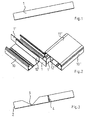
- Fig. 1 shows a bar for use as an extension of the partition wall 12, 12 'for chamber separation in the corner of blunt cable routing channels 10, 10'.
- the bar 1 may be made of any material, preferably plastic.
- Fig. 2 shows a flat corner formed from two cable trunking 10, 10 '.
- the channel lower parts 10, 10 ' have an approximately U-shaped cross-section, formed by a bottom and two side walls with lid holding profiles.
- In the interior of the channel lower parts 10, 10 ' is a formed of two parallel strips or lips partition 12, 12' formed. Between the lips of the partition wall 12, 12 'are in Fig. 1 shown strips 1, 1 'inserted. In the corner, the two strips 1, 1 'so far pulled out that they meet. In this way, the chamber separation is realized with the simplest means in the corner.
- a bar 1 " which provides as a coupling for the aligned connection of another channel section (not shown).
- Fig. 3 shows a bar 2, in which a starting from a longitudinal edge V-shaped recess 3 is incorporated. At this point, the bar 2 can be angled in the plane of the bar, preferably by 90 °.
- the strip 2 additionally has a V-shaped groove 4 incorporated in a side surface. At this point, the strip 2 can be angled forwards or backwards, preferably at 90 °.
- Fig. 4 shows a first application of the bar 2 at an outside corner.
- the strip 2 is angled at 90 ° at the V-shaped recess 3 to the rear and in the two double-walled partitions 12, 12 'of the lower channel part 10, 10' inserted.
- the channel lower parts 10, 10 ' are closed by matching lid 11, 11'.
- a matching molding (not shown) is plugged, the cable trunking is complete.
- Fig. 5 shows another example of use of the bar 2 in an inner corner.
- the strip 2 is angled in the region of the V-shaped recess 3 by 90 ° and inserted between the two lips of the partitions 12, 12 '.
- the chamber separation is complete. After fitting a suitable molded part on the remaining gap of the cable trunking is complete.
- Fig. 6 shows the application of the bar 2 in a flat corner.
- the strip 2 is angled in the region of the V-shaped groove 4 by 90 ° and inserted between the two lips of the partitions 12, 12 '. After placing a molding on the remaining gap, the channel is complete.
Landscapes
- Engineering & Computer Science (AREA)
- Architecture (AREA)
- Civil Engineering (AREA)
- Structural Engineering (AREA)
- Details Of Indoor Wiring (AREA)
- Installation Of Indoor Wiring (AREA)
- Electric Cable Installation (AREA)
- Extrusion Moulding Of Plastics Or The Like (AREA)
- Insulated Conductors (AREA)
- Near-Field Transmission Systems (AREA)
Description
- Die Erfindung betrifft Leitungsführungskanäle gemäß dem Oberbegriff des Anspruchs 1.
- Leitungsführungskanäle werden seit über 100 Jahren weltweit in großen Stückzahlen hergestellt, vertrieben und montiert. Sie besitzen üblicherweise ein U-bzw. C-förmiges Unterteil mit Boden, zwei Seitenwänden und Deckelhalteprofilen an den Seitenwänden und einen Deckel, der lösbar auf die Deckelhalteprofile aufrastbar ist. Trennwände im Inneren des Kanalunterteils unterteilen den Querschnitt in gegeneinander isolierte Kammern beispielsweise für Starkstromleitungen und Datenleitungen.
- Üblicherweise bestehen die Trennwände aus einer einfachen Leiste, die entweder einstückig mit dem Kanalunterteil hergestellt oder in Halteleisten am Boden des Kanals eingehängt werden kann. Aus der
FR 22 08 220 A FR 26 10 769 A - Es ist bekannt, dass Leitungsführungskanäle in Abschnitten von z. B. 2 m geliefert werden. Bei der Montage muss der Installateur daher mehrere dieser Abschnitte passend zueinander verlegen, und zwar entweder in gerade Linie oder auch im Winkel, meist im rechten Winkel.
- Für die Verlegung der Kanäle in gerader Linie bietet die Industrie spezielle Kupplungselemente an, die üblicherweise zwischen Boden und Deckelhalteprofil verklemmt werden.
- Für die Verlegung der Kanäle im Winkel gibt es zwei Möglichkeiten. Die sauberste Lösung besteht darin, die beiden benachbarten Kanalenden auf Gehrung zu schneiden. Dieses Verfahren ist jedoch zeit- und kostenaufwändig. Viel schneller geht die Verlegung der Kanäle mit stumpfem Stoß. Dabei ergibt sich jedoch das Problem, dass die die Starkstromleitungen und die Datenleitungen aufnehmenden Kammern nicht mehr gegeneinander abgeschottet sind. Aus diesem Grund bietet die Industrie zu jedem Kanal passende Formteile an, die auf die Kanäle aufgesetzt werden und durch geeignete Formgebung die Kammertrennung im Eckbereich wieder herstellen.
- Bei der Verlegung von Leitungsführungskanälen entstehen Innenecken, Außenecken und Flachecken. Für diese drei Ecken muss die Industrie zu der Kanalgröße und zu jedem Kanaltyp passende Formteile bereitstellen. Dies hat einen hohen Aufwand in der Entwicklung, der Produktion, der Lagerung und Versand sowie bei der Bestellung und der Montage zur Folge. Erfahrungsgemäß vertut sich der Installateur häufig bei der Bestellung der Formteile oder die Formteile gehen auf der Baustelle verloren, so dass der Installateur seine Arbeit nicht vollenden kann. Das ist unbefriedigend.
- In der
CH 582 962 - Der vorliegenden Erfindung liegt daher die Aufgabe zugrunde, einen Leitungsführungskanal der eingangs genannten Art anzugeben, dessen Kammern auch bei stumpf gestoßenen Ecken beliebiger Art gegeneinander abgeschottet werden können.
- Diese Aufgabe wird gelöst durch einen Leitungsführungskanal mit den Merkmalen des Anspruchs 1.
- Die vorliegende Erfindung verwendet eine einfache Leiste, die bereits beim Hersteller zwischen die beiden Lippen der Kanaltrennwand eingelegt werden kann. Bei der Montage vor Ort muss der Installateur die Leisten der beiden stumpf gestoßenen Kanäle nur so weit herausziehen, dass sie sich im Eckbereich berühren. Dadurch ist die gegenseitige Abschottung und Isolierung der Kammern für Starkstromleitungen und Datenleitungen hergestellt. Diese Lösung zeichnet sich durch eine hohe Flexibilität bei gleichzeitig minimalen Kosten aus.
- Ein weiterer Vorteil der erfindungsgemäßen Leiste besteht darin, dass sie bei der Verlegung der Kanäle in gerader Linie auch als Kupplung verwendet werden kann, so dass die Kanäle exakt fluchten.
- Gemäß einer Weiterbildung der Erfindung besitzt die Leiste eine von einer Längskante ausgehende V-förmige Aussparung. Im Bereich dieser Aussparung kann die Leiste in der Leistenebene abgewinkelt werden, beispielsweise um 90°. Dadurch ist es möglich, mit nur einer einzigen Leiste die Kammertrennung sowohl bei Innenecken als auch bei Außenecken zu bewirken.
- Gemäß einer weiteren Ausgestaltung der Erfindung besitzt die Leiste eine in eine Seitenfläche eingearbeitete V-förmige Nut. Dank dieser Nut kann die Leiste auch senkrecht zur Leitenebene abgewinkelt werden, beispielsweise um 90°. Dadurch ist es möglich, mit nur einer einzigen Leiste die Kammertrennung bei einem Flacheck zu bewirken.
- Anhand der Zeichnung soll die Erfindung in Form von Ausführungsbeispielen näher erläutert werden. Es zeigen jeweils als Schrägansicht
- Fig. 1
- eine Leiste zur Herstellung der Kammertrennung im Eckbereich von Leitungsführungskanälen,
- Fig. 2
- ein Flacheck aus zwei im rechten Winkel verlegten Kanälen mit Kammertrennung im Eckbereich,
- Fig. 3
- eine verbesserte Leiste,
- Fig. 4
- ein Außeneck aus zwei im rechten Winkel verlegten Kanälen mit Kammertrennung im Eckbereich unter Verwendung einer Leiste nach
Fig. 3 , - Fig. 5
- ein Inneneck aus zwei im rechten Winkel verlegten Kanälen mit Kammertrennung unter Verwendung der Leiste nach
Fig. 3 und - Fig. 6
- ein Flacheck aus zwei im rechten Winkel verlegten Kanälen mit Kammertrennung unter Verwendung einer Leiste nach
Fig. 3 . -
Fig. 1 zeigt eine Leiste zur Verwendung als Verlängerung der Trennwand 12, 12' zur Kammertrennung auch im Eckbereich von stumpf gestoßenen Leitungsführungskanälen 10, 10'. Die Leiste 1 kann aus beliebigem Material bestehen, bevorzugt aus Kunststoff. -
Fig. 2 zeigt ein aus zwei Leitungsführungskanälen 10, 10' gebildetes Flacheck. Die Kanalunterteile 10, 10' besitzen einen etwa U-förmigen Querschnitt, gebildet durch einen Boden und zwei Seitenwände mit Deckelhalteprofilen. Im Inneren der Kanalunterteile 10, 10' ist eine aus zwei parallelen Leisten oder Lippen gebildete Trennwand 12, 12' angeformt. Zwischen die Lippen der Trennwand 12, 12' sind die inFig. 1 dargestellten Leisten 1, 1' eingesteckt. Im Eckbereich sind die beiden Leisten 1, 1' so weit herausgezogen, dass sie sich treffen. Auf diese Weise ist die Kammertrennung mit einfachsten Mitteln auch im Eckbereich realisiert. - Wie die
Fig. 2 ferner erkennen lässt, kann die Leiste 1 weitere Funktionen übernehmen. In der Zeichnung ist links dargestellt eine Leiste 1", die als Kupplung für die fluchtende Verbindung eines weiteren Kanalabschnitts (nicht dargestellt) sorgt. -
Fig. 3 zeigt eine Leiste 2, in die eine von einer Längskante ausgehende V-förmige Aussparung 3 eingearbeitet ist. An dieser Stelle kann die Leiste 2 in der Leistenebene abgewinkelt werden, vorzugsweise um 90°. - Die Leiste 2 besitzt zusätzlich eine in eine Seitenfläche eingearbeitete V-förmige Nut 4. An dieser Stelle kann die Leiste 2 nach vorne oder hinten abgewinkelt werden, vorzugsweise um 90°.
-
Fig. 4 zeigt eine erste Anwendung der Leiste 2 bei einem Außeneck. Die Leiste 2 ist an der V-förmigen Aussparung 3 nach hinten um 90° abgewinkelt und in die beiden doppelwandigen Trennwände 12, 12' der Kanalunterteil 10, 10' eingesteckt. Die Kanalunterteile 10, 10' sind durch passende Deckel 11, 11' verschlossen. Sobald auf das Außeneck ein passendes Formteil (nicht dargestellt) aufgesteckt ist, ist der Leitungsführungskanal komplett. -
Fig. 5 zeigt ein weiteres Anwendungsbeispiel der Leiste 2 bei einem Inneneck. Die Leiste 2 ist im Bereich der V-förmigen Aussparung 3 um 90° abgewinkelt und zwischen die beiden Lippen der Trennwände 12, 12' gesteckt. Die Kammertrennung ist komplett. Nach Aufstecken eines passenden Formteils auf die noch bestehende Lücke ist der Leitungsführungskanal komplett. -
Fig. 6 zeigt die Anwendung der Leiste 2 bei einem Flacheck. Die Leiste 2 ist im Bereich der V-förmigen Nut 4 um 90° abgewinkelt und zwischen die beiden Lippen der Trennwände 12, 12' gesteckt. Nach Aufsetzen eines Formteils auf die noch bestehende Lücke ist der Kanal komplett.
Claims (3)
- Leitungsführungskanal, im wesentlichen umfassend- ein Kanalunterteil (10, 10') mit- einem Boden,- zwei Seitenwänden,- Deckelhalteprofilen an den Seitenwänden- und eine aus zwei parallelen, gegenseitig beabstandeten Lippen bestehende Trennwand (12, 12') im Kanalunterteil (10, 10')- und gegebenenfalls einen Deckel (11, 11'),gekennzeichnet durch das Merkmal:- zwischen den Lippen der Trennwand (12, 12') befindet sich eine einfache herausziehbare Leiste (1, 2).
- Leitungsführungskanal nach Anspruch 1, gekennzeichnet durch das Merkmal:- die Leiste (2) besitzt eine von einer Längskante ausgehende V-förmige Aussparung (3).
- Leitungsführungskanal nach Anspruch 1 oder 2, gekennzeichnet durch das Merkmal:- die Leiste (2) besitzt eine in eine Seitenfläche eingearbeitete V-förmige Nut (4).
Applications Claiming Priority (2)
| Application Number | Priority Date | Filing Date | Title |
|---|---|---|---|
| DE20202607U DE20202607U1 (de) | 2002-02-20 | 2002-02-20 | Leitungsführungskanal |
| DE20202607U | 2002-02-20 |
Publications (2)
| Publication Number | Publication Date |
|---|---|
| EP1339149A1 EP1339149A1 (de) | 2003-08-27 |
| EP1339149B1 true EP1339149B1 (de) | 2008-12-10 |
Family
ID=7968014
Family Applications (1)
| Application Number | Title | Priority Date | Filing Date |
|---|---|---|---|
| EP03002269A Expired - Lifetime EP1339149B1 (de) | 2002-02-20 | 2003-02-01 | Leitungsführungskanal |
Country Status (6)
| Country | Link |
|---|---|
| EP (1) | EP1339149B1 (de) |
| AT (1) | ATE417394T1 (de) |
| DE (2) | DE20202607U1 (de) |
| DK (1) | DK1339149T3 (de) |
| ES (1) | ES2316659T3 (de) |
| PT (1) | PT1339149E (de) |
Family Cites Families (4)
| Publication number | Priority date | Publication date | Assignee | Title |
|---|---|---|---|---|
| NL120180C (de) * | 1900-01-01 | |||
| ES1001593Y (es) * | 1987-02-11 | 1990-01-16 | Aparellaje Electrico S.A. | Moldura para conducciones electricas |
| FR2689202B1 (fr) * | 1992-03-26 | 1995-07-13 | Tech Modernes Alsaciennes | Element de couplage pour raccorder des goulottes de cables, et procede de fabrication de cet element. |
| US5917982A (en) * | 1998-01-05 | 1999-06-29 | The Wiremold Company | Fiber optic cable capable metal raceway system |
-
2002
- 2002-02-20 DE DE20202607U patent/DE20202607U1/de not_active Expired - Lifetime
-
2003
- 2003-02-01 EP EP03002269A patent/EP1339149B1/de not_active Expired - Lifetime
- 2003-02-01 PT PT03002269T patent/PT1339149E/pt unknown
- 2003-02-01 AT AT03002269T patent/ATE417394T1/de active
- 2003-02-01 DE DE50310884T patent/DE50310884D1/de not_active Expired - Lifetime
- 2003-02-01 ES ES03002269T patent/ES2316659T3/es not_active Expired - Lifetime
- 2003-02-01 DK DK03002269T patent/DK1339149T3/da active
Also Published As
| Publication number | Publication date |
|---|---|
| ES2316659T3 (es) | 2009-04-16 |
| DK1339149T3 (da) | 2009-03-23 |
| ATE417394T1 (de) | 2008-12-15 |
| DE50310884D1 (de) | 2009-01-22 |
| DE20202607U1 (de) | 2003-07-03 |
| EP1339149A1 (de) | 2003-08-27 |
| PT1339149E (pt) | 2009-02-18 |
Similar Documents
| Publication | Publication Date | Title |
|---|---|---|
| DE2908153C2 (de) | ||
| DE102017118005A1 (de) | Trockenbau-Trennwandsystem sowie Verfahren zur Montage eines derartigen Trockenbau-Trennwandsystems | |
| CH687225A5 (de) | Kabelkanalanordnung. | |
| DE102014101405A1 (de) | Bodenbaugruppe für das Rahmengestell eines Schaltschranks | |
| EP2763256A2 (de) | Kabelkanal mit Durchgangsabschluss, Bausatz für einen Durchgangsabschluss und Verfahren zum Montieren eines Durchgangsabschlusses für einen Kabelkanal | |
| DE2836862A1 (de) | Vorfertigungssystem fuer gebaeudewaende | |
| DE202014000932U1 (de) | Trockenbauplatte und Trockenbauwand | |
| EP1376795A2 (de) | Vorrichtung zum Installieren von Energieleitungen | |
| WO2008092699A1 (de) | Revisionsvorrichtung, insbesondere revisionsabdeckung | |
| EP1339149B1 (de) | Leitungsführungskanal | |
| DE2520441C3 (de) | Verfahren zum Isolieren von Gebäudewänden, insbesondere von Grundmauern gegen Feuchtigkeit, sowie eine Vorrichtung zum Ausführen des Verfahrens | |
| DE2625321A1 (de) | Elektrische installationseinrichtung | |
| EP1703609A1 (de) | Verfahren und Vorrichtung zum Herstellen einer Elektroinstallation in Trockenbauwänden | |
| EP3246613A1 (de) | Brandschutzplatte und modulbox | |
| DE19735957A1 (de) | Verfahren und Vorrichtung zum Herstellen von Bauelementen sowie danach hergestellte Bauelemente mit Vorinstallation | |
| DE102008048951A1 (de) | Kabelbahn | |
| DE19904394A1 (de) | Schachtelement zur Bildung eines in eine Gebäudewand integrierten Leerschachts | |
| EP1102376B1 (de) | Kabelkanal | |
| DE10114715B4 (de) | Verfahren zur Herstellung eines Stromschienensystems | |
| WO2008098691A1 (de) | Mehrteilige, in der flächenausdehnung variable revisionsvorrichtung | |
| EP1903162B1 (de) | Revisionsvorrichtung mit einem Revisionsrahmen und einem Revisionsdeckel | |
| DE2052438C3 (de) | Geräteträger für Elektroinstallation mit Wandleistenkanälen | |
| DE2126001C2 (de) | Verfahren zum Erstellen von Häusern | |
| DE2540840A1 (de) | Traeger fuer elektrische leitungen | |
| DE202023104429U1 (de) | Brandabschottung für Leitungen in Gebäuden |
Legal Events
| Date | Code | Title | Description |
|---|---|---|---|
| PUAI | Public reference made under article 153(3) epc to a published international application that has entered the european phase |
Free format text: ORIGINAL CODE: 0009012 |
|
| AK | Designated contracting states |
Designated state(s): AT BE BG CH CY CZ DE DK EE ES FI FR GB GR HU IE IT LI LU MC NL PT SE SI SK TR |
|
| AX | Request for extension of the european patent |
Extension state: AL LT LV MK RO |
|
| 17P | Request for examination filed |
Effective date: 20031024 |
|
| AKX | Designation fees paid |
Designated state(s): AT BE BG CH CY CZ DE DK EE ES FI FR GB GR HU IE IT LI LU MC NL PT SE SI SK TR |
|
| AXX | Extension fees paid |
Extension state: RO Payment date: 20031024 |
|
| RAP1 | Party data changed (applicant data changed or rights of an application transferred) |
Owner name: TEHALIT GMBH |
|
| RAP1 | Party data changed (applicant data changed or rights of an application transferred) |
Owner name: TEHALIT GMBH |
|
| 17Q | First examination report despatched |
Effective date: 20060424 |
|
| GRAP | Despatch of communication of intention to grant a patent |
Free format text: ORIGINAL CODE: EPIDOSNIGR1 |
|
| GRAS | Grant fee paid |
Free format text: ORIGINAL CODE: EPIDOSNIGR3 |
|
| GRAS | Grant fee paid |
Free format text: ORIGINAL CODE: EPIDOSNIGR3 |
|
| GRAA | (expected) grant |
Free format text: ORIGINAL CODE: 0009210 |
|
| AK | Designated contracting states |
Kind code of ref document: B1 Designated state(s): AT BE BG CH CY CZ DE DK EE ES FI FR GB GR HU IE IT LI LU MC NL PT SE SI SK TR |
|
| AX | Request for extension of the european patent |
Extension state: RO |
|
| REG | Reference to a national code |
Ref country code: GB Ref legal event code: FG4D Free format text: NOT ENGLISH |
|
| REG | Reference to a national code |
Ref country code: CH Ref legal event code: EP |
|
| REG | Reference to a national code |
Ref country code: IE Ref legal event code: FG4D Free format text: LANGUAGE OF EP DOCUMENT: GERMAN |
|
| REF | Corresponds to: |
Ref document number: 50310884 Country of ref document: DE Date of ref document: 20090122 Kind code of ref document: P |
|
| REG | Reference to a national code |
Ref country code: CH Ref legal event code: NV Representative=s name: PATENTANWAELTE SCHAAD, BALASS, MENZL & PARTNER AG |
|
| REG | Reference to a national code |
Ref country code: PT Ref legal event code: SC4A Free format text: AVAILABILITY OF NATIONAL TRANSLATION Effective date: 20090211 |
|
| REG | Reference to a national code |
Ref country code: GR Ref legal event code: EP Ref document number: 20090400618 Country of ref document: GR |
|
| REG | Reference to a national code |
Ref country code: DK Ref legal event code: T3 |
|
| REG | Reference to a national code |
Ref country code: ES Ref legal event code: FG2A Ref document number: 2316659 Country of ref document: ES Kind code of ref document: T3 |
|
| PG25 | Lapsed in a contracting state [announced via postgrant information from national office to epo] |
Ref country code: FI Free format text: LAPSE BECAUSE OF FAILURE TO SUBMIT A TRANSLATION OF THE DESCRIPTION OR TO PAY THE FEE WITHIN THE PRESCRIBED TIME-LIMIT Effective date: 20081210 Ref country code: SI Free format text: LAPSE BECAUSE OF FAILURE TO SUBMIT A TRANSLATION OF THE DESCRIPTION OR TO PAY THE FEE WITHIN THE PRESCRIBED TIME-LIMIT Effective date: 20081210 |
|
| REG | Reference to a national code |
Ref country code: IE Ref legal event code: FD4D |
|
| PG25 | Lapsed in a contracting state [announced via postgrant information from national office to epo] |
Ref country code: IE Free format text: LAPSE BECAUSE OF FAILURE TO SUBMIT A TRANSLATION OF THE DESCRIPTION OR TO PAY THE FEE WITHIN THE PRESCRIBED TIME-LIMIT Effective date: 20081210 Ref country code: EE Free format text: LAPSE BECAUSE OF FAILURE TO SUBMIT A TRANSLATION OF THE DESCRIPTION OR TO PAY THE FEE WITHIN THE PRESCRIBED TIME-LIMIT Effective date: 20081210 Ref country code: BG Free format text: LAPSE BECAUSE OF FAILURE TO SUBMIT A TRANSLATION OF THE DESCRIPTION OR TO PAY THE FEE WITHIN THE PRESCRIBED TIME-LIMIT Effective date: 20090310 |
|
| PG25 | Lapsed in a contracting state [announced via postgrant information from national office to epo] |
Ref country code: SE Free format text: LAPSE BECAUSE OF FAILURE TO SUBMIT A TRANSLATION OF THE DESCRIPTION OR TO PAY THE FEE WITHIN THE PRESCRIBED TIME-LIMIT Effective date: 20090310 |
|
| PG25 | Lapsed in a contracting state [announced via postgrant information from national office to epo] |
Ref country code: SK Free format text: LAPSE BECAUSE OF FAILURE TO SUBMIT A TRANSLATION OF THE DESCRIPTION OR TO PAY THE FEE WITHIN THE PRESCRIBED TIME-LIMIT Effective date: 20081210 Ref country code: MC Free format text: LAPSE BECAUSE OF NON-PAYMENT OF DUE FEES Effective date: 20090228 |
|
| PLBE | No opposition filed within time limit |
Free format text: ORIGINAL CODE: 0009261 |
|
| STAA | Information on the status of an ep patent application or granted ep patent |
Free format text: STATUS: NO OPPOSITION FILED WITHIN TIME LIMIT |
|
| 26N | No opposition filed |
Effective date: 20090911 |
|
| GBPC | Gb: european patent ceased through non-payment of renewal fee |
Effective date: 20090310 |
|
| PG25 | Lapsed in a contracting state [announced via postgrant information from national office to epo] |
Ref country code: GB Free format text: LAPSE BECAUSE OF NON-PAYMENT OF DUE FEES Effective date: 20090310 |
|
| PG25 | Lapsed in a contracting state [announced via postgrant information from national office to epo] |
Ref country code: IT Free format text: LAPSE BECAUSE OF FAILURE TO SUBMIT A TRANSLATION OF THE DESCRIPTION OR TO PAY THE FEE WITHIN THE PRESCRIBED TIME-LIMIT Effective date: 20081210 |
|
| PG25 | Lapsed in a contracting state [announced via postgrant information from national office to epo] |
Ref country code: LU Free format text: LAPSE BECAUSE OF NON-PAYMENT OF DUE FEES Effective date: 20090201 |
|
| PGFP | Annual fee paid to national office [announced via postgrant information from national office to epo] |
Ref country code: DK Payment date: 20110222 Year of fee payment: 9 |
|
| PGFP | Annual fee paid to national office [announced via postgrant information from national office to epo] |
Ref country code: CZ Payment date: 20110128 Year of fee payment: 9 Ref country code: DE Payment date: 20110221 Year of fee payment: 9 Ref country code: CH Payment date: 20110222 Year of fee payment: 9 Ref country code: AT Payment date: 20110217 Year of fee payment: 9 Ref country code: PT Payment date: 20110124 Year of fee payment: 9 Ref country code: NL Payment date: 20110225 Year of fee payment: 9 Ref country code: FR Payment date: 20110301 Year of fee payment: 9 |
|
| PG25 | Lapsed in a contracting state [announced via postgrant information from national office to epo] |
Ref country code: HU Free format text: LAPSE BECAUSE OF FAILURE TO SUBMIT A TRANSLATION OF THE DESCRIPTION OR TO PAY THE FEE WITHIN THE PRESCRIBED TIME-LIMIT Effective date: 20090611 |
|
| PGFP | Annual fee paid to national office [announced via postgrant information from national office to epo] |
Ref country code: GR Payment date: 20110225 Year of fee payment: 9 |
|
| PGFP | Annual fee paid to national office [announced via postgrant information from national office to epo] |
Ref country code: ES Payment date: 20110221 Year of fee payment: 9 Ref country code: BE Payment date: 20110221 Year of fee payment: 9 |
|
| PG25 | Lapsed in a contracting state [announced via postgrant information from national office to epo] |
Ref country code: TR Free format text: LAPSE BECAUSE OF FAILURE TO SUBMIT A TRANSLATION OF THE DESCRIPTION OR TO PAY THE FEE WITHIN THE PRESCRIBED TIME-LIMIT Effective date: 20081210 |
|
| PG25 | Lapsed in a contracting state [announced via postgrant information from national office to epo] |
Ref country code: CY Free format text: LAPSE BECAUSE OF FAILURE TO SUBMIT A TRANSLATION OF THE DESCRIPTION OR TO PAY THE FEE WITHIN THE PRESCRIBED TIME-LIMIT Effective date: 20081210 |
|
| REG | Reference to a national code |
Ref country code: PT Ref legal event code: MM4A Free format text: LAPSE DUE TO NON-PAYMENT OF FEES Effective date: 20120801 |
|
| BERE | Be: lapsed |
Owner name: TEHALIT G.M.B.H. Effective date: 20120228 |
|
| REG | Reference to a national code |
Ref country code: NL Ref legal event code: V1 Effective date: 20120901 |
|
| REG | Reference to a national code |
Ref country code: CH Ref legal event code: PL |
|
| REG | Reference to a national code |
Ref country code: GR Ref legal event code: ML Ref document number: 20090400618 Country of ref document: GR Effective date: 20120905 |
|
| PG25 | Lapsed in a contracting state [announced via postgrant information from national office to epo] |
Ref country code: CH Free format text: LAPSE BECAUSE OF NON-PAYMENT OF DUE FEES Effective date: 20120229 Ref country code: LI Free format text: LAPSE BECAUSE OF NON-PAYMENT OF DUE FEES Effective date: 20120229 Ref country code: CZ Free format text: LAPSE BECAUSE OF NON-PAYMENT OF DUE FEES Effective date: 20120201 |
|
| REG | Reference to a national code |
Ref country code: DK Ref legal event code: EBP |
|
| REG | Reference to a national code |
Ref country code: FR Ref legal event code: ST Effective date: 20121031 |
|
| PG25 | Lapsed in a contracting state [announced via postgrant information from national office to epo] |
Ref country code: GR Free format text: LAPSE BECAUSE OF NON-PAYMENT OF DUE FEES Effective date: 20120905 Ref country code: PT Free format text: LAPSE BECAUSE OF NON-PAYMENT OF DUE FEES Effective date: 20120801 |
|
| REG | Reference to a national code |
Ref country code: DE Ref legal event code: R119 Ref document number: 50310884 Country of ref document: DE Effective date: 20120901 |
|
| REG | Reference to a national code |
Ref country code: AT Ref legal event code: MM01 Ref document number: 417394 Country of ref document: AT Kind code of ref document: T Effective date: 20120201 |
|
| PG25 | Lapsed in a contracting state [announced via postgrant information from national office to epo] |
Ref country code: BE Free format text: LAPSE BECAUSE OF NON-PAYMENT OF DUE FEES Effective date: 20120228 |
|
| PG25 | Lapsed in a contracting state [announced via postgrant information from national office to epo] |
Ref country code: AT Free format text: LAPSE BECAUSE OF NON-PAYMENT OF DUE FEES Effective date: 20120201 Ref country code: FR Free format text: LAPSE BECAUSE OF NON-PAYMENT OF DUE FEES Effective date: 20120229 Ref country code: NL Free format text: LAPSE BECAUSE OF NON-PAYMENT OF DUE FEES Effective date: 20120901 |
|
| PG25 | Lapsed in a contracting state [announced via postgrant information from national office to epo] |
Ref country code: DE Free format text: LAPSE BECAUSE OF NON-PAYMENT OF DUE FEES Effective date: 20120901 |
|
| REG | Reference to a national code |
Ref country code: ES Ref legal event code: FD2A Effective date: 20130708 |
|
| PG25 | Lapsed in a contracting state [announced via postgrant information from national office to epo] |
Ref country code: ES Free format text: LAPSE BECAUSE OF NON-PAYMENT OF DUE FEES Effective date: 20120202 |
|
| PG25 | Lapsed in a contracting state [announced via postgrant information from national office to epo] |
Ref country code: DK Free format text: LAPSE BECAUSE OF NON-PAYMENT OF DUE FEES Effective date: 20120229 |