EP1339007A1 - Optoelektronischer Codeleser - Google Patents
Optoelektronischer Codeleser Download PDFInfo
- Publication number
- EP1339007A1 EP1339007A1 EP03001666A EP03001666A EP1339007A1 EP 1339007 A1 EP1339007 A1 EP 1339007A1 EP 03001666 A EP03001666 A EP 03001666A EP 03001666 A EP03001666 A EP 03001666A EP 1339007 A1 EP1339007 A1 EP 1339007A1
- Authority
- EP
- European Patent Office
- Prior art keywords
- scanning
- codes
- scanning device
- code reader
- reading area
- Prior art date
- Legal status (The legal status is an assumption and is not a legal conclusion. Google has not performed a legal analysis and makes no representation as to the accuracy of the status listed.)
- Granted
Links
Images

Classifications
-
- G—PHYSICS
- G06—COMPUTING OR CALCULATING; COUNTING
- G06K—GRAPHICAL DATA READING; PRESENTATION OF DATA; RECORD CARRIERS; HANDLING RECORD CARRIERS
- G06K7/00—Methods or arrangements for sensing record carriers, e.g. for reading patterns
- G06K7/10—Methods or arrangements for sensing record carriers, e.g. for reading patterns by electromagnetic radiation, e.g. optical sensing; by corpuscular radiation
- G06K7/10544—Methods or arrangements for sensing record carriers, e.g. for reading patterns by electromagnetic radiation, e.g. optical sensing; by corpuscular radiation by scanning of the records by radiation in the optical part of the electromagnetic spectrum
- G06K7/10821—Methods or arrangements for sensing record carriers, e.g. for reading patterns by electromagnetic radiation, e.g. optical sensing; by corpuscular radiation by scanning of the records by radiation in the optical part of the electromagnetic spectrum further details of bar or optical code scanning devices
- G06K7/10861—Methods or arrangements for sensing record carriers, e.g. for reading patterns by electromagnetic radiation, e.g. optical sensing; by corpuscular radiation by scanning of the records by radiation in the optical part of the electromagnetic spectrum further details of bar or optical code scanning devices sensing of data fields affixed to objects or articles, e.g. coded labels
-
- G—PHYSICS
- G06—COMPUTING OR CALCULATING; COUNTING
- G06K—GRAPHICAL DATA READING; PRESENTATION OF DATA; RECORD CARRIERS; HANDLING RECORD CARRIERS
- G06K7/00—Methods or arrangements for sensing record carriers, e.g. for reading patterns
- G06K7/10—Methods or arrangements for sensing record carriers, e.g. for reading patterns by electromagnetic radiation, e.g. optical sensing; by corpuscular radiation
- G06K7/10544—Methods or arrangements for sensing record carriers, e.g. for reading patterns by electromagnetic radiation, e.g. optical sensing; by corpuscular radiation by scanning of the records by radiation in the optical part of the electromagnetic spectrum
- G06K7/10792—Special measures in relation to the object to be scanned
-
- G—PHYSICS
- G06—COMPUTING OR CALCULATING; COUNTING
- G06K—GRAPHICAL DATA READING; PRESENTATION OF DATA; RECORD CARRIERS; HANDLING RECORD CARRIERS
- G06K2207/00—Other aspects
- G06K2207/1016—Motor control or optical moving unit control
Definitions
- the invention relates to an optoelectronic code reader and a method for reading codes that are relative within a reading area move to the code reader, the reading area at least along one Scanning direction is scanned.
- Such a reading of codes takes place, for example, with a barcode scanner in that a laser beam by means of a rotating polygon mirror periodically along the scanning direction across the reading area is performed, wherein the reflected light is fed to a light receiver becomes. Depending on whether the laser beam is on a light or a dark one Surface is reflected, a different amount of light strikes the recipient.
- the corresponding output signals from the receiver are determined by means of an evaluation device for the presence and possibly the content of a bar code evaluated.
- Optical codes can also be used, for example, using a line scan camera are read in by means of a plurality of light-receiving elements arranged in a row a line-shaped line corresponding to the scanning direction Image information can be scanned at the same time in order subsequently evaluate for the presence of a code.
- the scanning of the reading area is at least along the scanning direction required with such code readers, since with the usual codes Information to be read in along an information arrangement direction is encrypted.
- Information to be read in along an information arrangement direction is encrypted.
- a barcode consists of bright and dark bars side by side along the information arrangement direction are arranged. Only if the scanning direction matches the information ordering direction matches or relative to this at most the code can be read in correctly become.
- a code reader and a reading method to create the reading in an easy to implement way of codes fed into the reading area also enable when multiple codes are arranged along the scanning direction of the code reader and are at different distances from the code reader.
- the reading in of codes introduced into the reading area - at least temporarily - in a cooperative manner Coordination between the scanning devices, namely by the Focus positions of the scanning devices alternately on the next one code inserted in the reading area.
- each scanning device takes over the reading of a certain one Codes in the reading area of the code reader in order to complete such Read the next code to enter the reading area introduced and in the meantime not yet from another scanner has been recorded.
- the focusing of the scanning devices is preferably controlled depending on the number of codes in the reading area of the code reader. As an alternative or in addition, the control is dependent on the mutual distance between the codes in the reading area. Further can focus positions depending on the mutual relative position of the codes are controlled with respect to the scanning direction of the code reader in order to focus the scanning devices individually, for example to be provided if two codes are adjacent in the scanning direction are arranged to each other. Such a control enables individual focusing of the redundantly arranged scanning devices in different focus positions if and only if predetermined detection criteria are met, the risk of existence differently spaced codes in an arrangement along the Show scanning direction.
- the scanning devices are preferably controlled in such a way that optionally the explained cooperative focus on different codes takes place or - especially when there is a large mutual distance between the codes Standard focusing takes place in which all scanning devices have one assume a common focus position that is optimal for the current reading task.
- Standard focusing takes place in which all scanning devices have one assume a common focus position that is optimal for the current reading task.
- from the cooperative focus to the standard focus to be switched when the explained detection criteria to identify a potentially problematic reading task are not met, or if the last code in the reading area successful according to the cooperative focus of the scanning devices has been imported.
- Such a switchover to the standard focusing of the scanning devices on a common focus position has the advantage that the multiple scanners for redundancy generation of the information read in can be used, for example a single code read by multiple scanners can and the code information obtained in each case Control purposes can be compared with each other.
- the code reader - as a master scanner - has one Has image capture sensor through which the explained detection criteria can be determined for a potentially difficult reading task. Accordingly, such an image capture sensor can be used to capture the Number of codes in the reading area to record the mutual Distance of the codes in the reading area, and / or to record the Relative arrangement of the codes with respect to the scanning direction of the code reader used to send this information to a controller for forward the scanning devices. For these purposes, it is sufficient if the image capture sensor is the reading area or an upstream Detection area recorded in two dimensions. The relative arrangement the code can be determined directly or from the recorded object arrangement be derived.
- a simple optoelectronic or other Object detection sensor can be provided to prevent intrusion or presence of objects in the reading area and the Control the reading process accordingly.
- a Conveyor belt can be arranged around a light barrier or a light sensor to detect the passing of conveyed goods at which the goods to be read in Codes are then suspected. Based on the information provided by the sensor about the location of an object and due to tracking of the Object movement - for example by incremental encoders on a conveyor belt - can thus infer the position of a code to be read become. This is a control for cooperative focusing also possible without using the image acquisition sensor mentioned.
- the code reader has at least one distance measuring device has, by means of which the distance between the in the Reading area guided codes and the code reader can be determined. This distance information is used for control and possibly individual Focusing of the scanning devices used. Any scanner A separate distance measuring device can also be assigned.
- Another problem with known code readers is a geometrical one Shadowing of the scanning beam of the code reader concerned by an object in the reading area, so that one in the scanning shadow code arranged for this object cannot be read correctly. Furthermore, there is the problem with known code readers that with codes Under transparent film, total reflections on the film occur and a correct one Prevent reading of the code information.
- the scanning beam paths inclined to each other run. Due to the presence of multiple scanners for the same scanning direction the reading range of the code reader can be Scanning beams are recorded at different angles of inclination, so that the inclinations can be chosen so that it is for the scanning devices there are no common shading areas and also Total reflections or other reflection effects can be avoided.
- This Further training is particularly advantageous if the code information be read in redundantly, i.e. when the scanning devices according to the explained standard focus on a common one Focus position are set.
- the respective scanning beam path of the scanning devices a slight angle of inclination (Skew angle) with respect to the orthogonal to the reading surface, so with respect to the orthogonal to the direction that is perpendicular to the direction of the relative movement of the code reader and codes on the one hand and on the other hand stands for the direction of extension of the codes.
- This Tilt angle can be, for example, between 2 ° and 20 °, in particular approx. 10 °.
- an inclined arrangement of the scanning devices can be used relative to each other with respect to the direction of the relative movement be provided by code readers and codes, so that for example the first scanning device obliquely in the direction of movement of the codes and second scanning device obliquely against the direction of movement of the Codes is inclined.
- the scanning devices can therefore each own light transmitter, own transmission optics, own reception optics, your own light receiver and / or your own evaluation device have.
- the invention can also be implemented by that the first scanner and the second scanner - at least partially - are formed by a common scanning unit.
- the scanning devices are therefore a common light transmitter, a common transmitting optics, a common receiving optics, a common light receiver and / or a common evaluation device intended.
- scanning along scan lines takes place, which are each assigned to a scanning direction and in the reading area run parallel to each other.
- the Scanning lines of the various scanning devices are thus selected in this way that they are each parallel to the common scan direction run and are sufficiently spaced from each other to to ensure that the scanning devices or the associated Scanning beams do not cause any mutual interference in the reading processes.
- the scanning lines of the multiple scanning devices coincide along the reading area of the code reader. This is possible in particular if the relevant scanning devices - at least in part - by a common scanning unit are formed.
- the invention and the advantages associated with it can also be even if the scanning of the reading area by the first and second scanning device not exactly parallel to the above Scanning direction of the code reader takes place, but when the respective scanning lines run at an acute angle to each other or in cut at an acute angle.
- the decisive factor is that a code can be read by both scanning devices must, its information arrangement direction parallel to the scanning direction of the code reader runs. However, this is for a barcode for example, even if it is along scan lines is scanned at a scanning limit angle of +/- 30 ° to the Alignment or the information arrangement direction of the code.
- the code reader is in addition to scanning the reading area along another scanning direction educated. Scanning the reading area along the scanning direction and the further, in this respect diagonally running scanning direction enables the reading of codes in any angular position their direction of information arrangement (omnidirectional reading).
- the code reader is also preferred with regard to these Scanning direction for scanning the reading area in different focus positions controllable to also with respect to this further scanning direction multiple codes at different intervals easily and quickly to be able to read.
- the invention for reading in one-dimensional or two-dimensional codes and therefore for example for barcode scanners, line scan cameras or matrix cameras can be used. It is also possible to use two scanning devices instead in a redundant arrangement three or more scanning devices for scanning along a common scanner in different To provide focus positions.
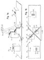
- 3a and 3b show a conventional bar code scanner 11 and a typical reading situation.
- a conveyor belt 13 By means of a conveyor belt 13, several Packets 15, 17, 19, 21 along a conveying direction 23 through a reading area 25 of the barcode scanner 11 moves.
- Each package is 15, 17, 19, 21 provided with a one-dimensional code 27, 29, 31 or 33.
- the barcode scanner 11 scans the reading area 25 by an am Reading area 25 appearing point-like - laser beam over the Conveyor belt 13 is guided. By making this scanning beam with a high Sampling rate along a scanning direction 35 periodically over the reading area 25 is performed, the scanning ultimately takes place along a scanning line 37, the top view according to FIG. 3b - in an idealized representation - appears straight throughout. Once a code 29, 31 along this Scanning line 37 and thus along the scanning direction 35 can be detected the barcode scanner 11 on the basis of those caused by the code 29, 31 Contrast ratios of the reflected light encoded therein Read in and evaluate information.
- a problem with the bar code scanner 11 shown in FIGS. 3a and 3b is that it only has a limited depth of field and therefore not without changing its focus position in the meantime Codes 29 and 31 can be read in on packets 17 and 19 in different Are arranged height and along the scanning direction 35th thus take different distances from the bar code scanner 11.
- An interim change in the focus position of the barcode scanner 11 during the scanning beam in the scanning direction 35 along the scanning line 37 takes a comparatively long time, so the scanning beam is slow along the scanning direction 35 can be performed. Accordingly, the conveyor belt 13 can only to be moved slowly in the conveying direction 23 between successive Scans not to skip intermediate codes.
- the focus position of the barcode scanner 11 is not adjusted codes 29 and 31 cannot both be read correctly.
- first scanning device for scanning the reading area 25 39 and a second scanning device 39 ' are provided. These are, for example constructed like a barcode scanner so that it the reading area 25 each by means of a periodically along the scanning direction 35 scan the deflected laser beam. This is done accordingly this scanning of the reading area 35 according to FIG. 1b along a first Scan line 37 and a second scan line 37 '.
- the scan lines 37 and 37 ' run in the scanning direction 35 and thus parallel to one another, and they are - according to an offset arrangement of the scanning devices 39, 39 '- slightly with respect to the conveying direction 23 spaced from each other.
- the scanning devices 39, 39 '- at least if necessary - can be controlled so that they have different focus positions take in.
- the code reader according to FIGS. 1a and 1b can Codes that are arranged along the scanning direction 35 and thereby have different distances to the code readers, each adjusted Read focus position.
- the scanning devices 39, 39 ' are preferably controlled by means of a - not shown in Fig. 1a and 1b - control device with an image acquisition sensor, also not shown, is connected. This determines the number of those currently present in the reading area 25 Codes 29, 31. If a predetermined minimum number of codes 29, 31, for example at least two codes, is triggered the control device the scanning devices 39, 39 'to a cooperative Focusing. This means that each of the scanning devices 39, 39 'each focused on a code 29, 31 and after successful reading of the relevant code 29, 31 their focus position on the next "free", i.e. from the other scanner 39 'or 39 still not set code 27.
- the control device initiates the two scanning devices 39, 39 'to a standard focusing. This means that the scanning devices 39, 39 'have a common one Set the focus position for the code currently in reading area 25.
- Object detection sensor can be provided, ie a sensor for detection of objects without capturing resolved image information.
- FIG. 1a and 1b show a further development of the invention, in which the scanning devices 39, 39 'in addition to scanning the reading area 25 are formed along a further scanning direction 41.
- the Scanning line 37 and the further scanning line 43 of the first scanning device 39, and the scan line 37 'and the further scan line 43' of the second Scanning device 39 ' run vertically in the plan view according to FIG. 1b to each other and therefore appear X-shaped.
- This scanning of the reading area 25 along the scanning direction 35 and the further scanning direction 41 causes the codes 27, 29, 31, 33 can basically be read in any rotational position, since always either the scanning direction 35 or the further scanning direction 41 are also sufficient the information arrangement direction of the code concerned.
- the code in question is always either from the scan lines 37, 37 'or from the further scan lines 43, 43' completely detected.
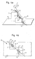
- FIG. 4a and 4b show a further problem that occurs with known code readers can occur.
- a barcode scanner 11 is shown in FIG. 4a a comparatively small distance above a packet 17 is on the top of which a code 29 to be read is arranged.
- scanning takes place along a scanning direction 35, so that the Guiding the scanning beam in the top view according to FIG. 4b as a scanning line 37 appears.
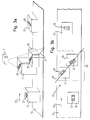
- 2a and 2b show a further development of the embodiment 1a and 1b that the scanning devices 39, 39 'to for this purpose have inclined scanning beam paths.
- the scanning devices 39, 39 'are along the conveying direction 23 are spaced from each other and they are in relation to the Vertical by an angle of 10 ° in or against the Delivery direction 23 inclined. This causes there to be no common ones Shading areas of the two scanning devices 39, 39 'are and therefore codes on low packets 19 can always be read.
- the top view according to FIG. 2b shows that due to the respective inclination of the scanning devices 39, 39 'and the different height of the Packets 17, 19 and the conveyor belt 13, the scanning lines 37, 37 'only in certain areas have a straight course.
Landscapes
- Physics & Mathematics (AREA)
- Engineering & Computer Science (AREA)
- Electromagnetism (AREA)
- General Physics & Mathematics (AREA)
- Toxicology (AREA)
- General Health & Medical Sciences (AREA)
- Artificial Intelligence (AREA)
- Computer Vision & Pattern Recognition (AREA)
- Health & Medical Sciences (AREA)
- Theoretical Computer Science (AREA)
- Mechanical Optical Scanning Systems (AREA)
- Nitrogen Condensed Heterocyclic Rings (AREA)
- Light Receiving Elements (AREA)
- Absorbent Articles And Supports Therefor (AREA)
- Sorting Of Articles (AREA)
- Character Input (AREA)
Abstract
Description
- Fig. 1a und 1b
- einen erfindungsgemäßen Codeleser und die entsprechende Lesesituation in einer Perspektivansicht bzw. einer Draufsicht,
- Fig. 2a und 2b
- eine weitere Ausführungsform eines erfindungsgemäßen Codelesers und der entsprechenden Lesesituation in einer Perspektivansicht bzw. einer Draufsicht,
- Fig. 3a und 3b
- einen bekannten Codeleser und die entsprechende Lesesituation in einer Perspektivansicht bzw. einer Draufsicht, und
- Fig. 4a und 4b
- einen bekannten Codeleser und die entsprechende Lesesituation in einer Perspektivansicht bzw. einer Draufsicht.
- 11
- Barcodescanner
- 13
- Förderband
- 15, 17, 19, 21
- Paket
- 23
- Förderrichtung
- 25
- Lesebereich
- 27, 29, 31, 33
- Code
- 35
- Abtastrichtung
- 37, 37'
- Abtastlinie
- 39
- erste Abtasteinrichtung
- 39'
- zweite Abtasteinrichtung
- 41
- weitere Abtastrichtung
- 43, 43'
- weitere Abtastlinie
- 45, 47, 49
- Abschattungsbereich
- 51, 53
- effektiver Leseabschnitt
Claims (16)
- Optoelektronischer Codeleser zum Einlesen von Codes (27, 29, 31, 33) , die sich innerhalb eines Lesebereichs (25) relativ zu dem Codeleser bewegen, durch Abtasten des Lesebereichs zumindest entlang einer Abtastrichtung (35),
wobei zum Einlesen von Codes (29, 31), die entlang der Abtastrichtung (35) in unterschiedlichen Abständen zu dem Codeleser angeordnet sind, wenigstens eine erste Abtasteinrichtung (39) und eine zweite Abtasteinrichtung (39') vorgesehen sind, die zum Abtasten entlang der Abtastrichtung (35) in unterschiedlichen Fokuslagen steuerbar sind. - Codeleser nach Anspruch 1,
dadurch gekennzeichnet, dass die Abtasteinrichtungen (39, 39') derart steuerbar sind, dass die Fokuslagen der ersten Abtasteinrichtung (39) und der zweiten Abtasteinrichtung (39') abwechselnd auf den jeweils nächsten in den Lesebereich bewegten Code (27, 29, 31) eingestellt werden. - Codeleser nach einem der vorhergehenden Ansprüche,
dadurch gekennzeichnet, dass die Fokuslagen der Abtasteinrichtungen (39, 39') in Abhängigkeit von der Anzahl der Codes (29, 31) im Lesebereich (25), in Abhängigkeit von dem gegenseitigen Abstand der Codes und/oder in Abhängigkeit von der Relativanordnung der Codes bezüglich der Abtastrichtung steuerbar sind. - Codeleser nach einem der vorhergehenden Ansprüche,
dadurch gekennzeichnet, dass die Abtasteinrichtungen (39, 39') derart steuerbar sind, dassbei Vorhandensein einer vorbestimmten Mindestanzahl von Codes (29, 31) im Lesebereich (25), bei Unterschreiten eines vorbestimmten gegenseitigen Mindestabstands der Codes im Lesebereich und/oder bei Anordnung mehrerer Codes entlang der Abtastrichtung nebeneinander die Fokuslagen der ersten Abtasteinrichtung (39) und der zweiten Abtasteinrichtung (39') auf verschiedene Codes (29, 31) eingestellt werden, undansonsten und/oder nach erfolgreichem Einlesen der Codes die erste Abtasteinrichtung (39) und die zweite Abtasteinrichtung (39') auf eine gemeinsame Fokuslage eingestellt werden. - Codeleser nach einem der vorhergehenden Ansprüche,
dadurch gekennzeichnet, dass der Codeleser einen Bilderfassungssensor oder Objekterfassungssensor aufweist zur Erfassung der Anzahl der Codes (29, 31) im Lesebereich, zur Erfassung des gegenseitigen Abstands der Codes im Lesebereich und/oder zur Erfassung der Relativanordnung der Codes bezüglich der Abtastrichtung, und/oder
dass der Codeleser wenigstens eine Abstandsmesseinrichtung zur Bestimmung des Abstands zwischen einem Code (29, 31) und dem Codeleser aufweist, und/oder
dass der Codeleser als Barcodescanner (39, 39') , Zeilenkamera oder Matrixkamera ausgebildet ist. - Codeleser nach einem der vorhergehenden Ansprüche,
dadurch gekennzeichnet, dass zur Vermeidung einer geometrischen Abschattung eines Abtaststrahls einer Abtasteinrichtung (39, 39') durch ein im Lesebereich befindliches Objekt (17, 19) oder zur Vermeidung von Reflexionseffekten an dem abzutastenden Codedie erste Abtasteinrichtung (39) und die zweite Abtasteinrichtung (39') geneigt zueinander verlaufende Abtaststrahlengänge aufweisen und/oderdie erste Abtasteinrichtung (39) und die zweite Abtasteinrichtung (39') beabstandet voneinander angeordnet sind. - Codeleser nach Anspruch 6,
dadurch gekennzeichnet, dass der Neigungswinkel des Abtaststrahlengangs einer Abtasteinrichtung (39, 39') bezüglich der Orthogonalen auf der Richtung (23) der Relativbewegung von Codeleser und Codes zwischen 2° und 20°, insbesondere ca. 10° beträgt, und/oder
dass der Abtaststrahlengang der ersten Abtasteinrichtung (39) in Richtung (23) der Relativbewegung von Codeleser und Codes geneigt und der Abtaststrahlengang der zweiten Abtasteinrichtung (39') entgegen dieser Richtung (23) geneigt verläuft und/oder
dass die erste Abtasteinrichtung (39) und die zweite Abtasteinrichtung (39') bezüglich der Richtung (23) der Relativbewegung von Codeleser und Codes beabstandet voneinander angeordnet sind. - Codeleser nach einem der vorhergehenden Ansprüche,
dadurch gekennzeichnet, dass die erste Abtasteinrichtung (39) und die zweite Abtasteinrichtung (39') - zumindest teilweise - durch separate Einheiten gebildet sind, oder
dass die erste Abtasteinrichtung (39) und die zweite Abtasteinrichtung (39') - zumindest teilweise - durch eine gemeinsame Abtasteinheit gebildet sind. - Codeleser nach einem der vorhergehenden Ansprüche,
dadurch gekennzeichnet, dass die erste Abtasteinrichtung (39) und die zweite Abtasteinrichtung (39') zum Abtasten des Lesebereichs (25) entlang parallel benachbarter Abtastlinien (37, 37'; 43, 43') ausgebildet sind, oder dass die erste Abtasteinrichtung und die zweite Abtasteinrichtung zum Abtasten des Lesebereichs entlang übereinstimmender Abtastlinien ausgebildet sind, oder
dass die erste Abtasteinrichtung und die zweite Abtasteinrichtung zum Abtasten des Lesebereichs entlang von Abtastlinien ausgebildet sind, die in einem spitzen Winkel schräg zueinander verlaufen. - Codeleser nach einem der vorhergehenden Ansprüche,
dadurch gekennzeichnet, dass die Abtastrichtung (35) bezüglich der Richtung (23) der Relativbewegung von Codeleser und Codes diagonal verläuft, und/oder dass der Codeleser zusätzlich zum Abtasten des Lesebereichs (25) wenigstens entlang einer weiteren Abtastrichtung (41) ausgebildet ist. - Codeleser nach Anspruch 10,
dadurch gekennzeichnet, dass die Abtastrichtung (35) und die weitere Abtastrichtung (41) diagonal oder senkrecht zueinander verlaufen, und/oder der Codeleser auch bezüglich der weiteren Abtastrichtung (41) zum Abtasten in unterschiedlichen Fokuslagen vorgesehen ist, und/oder
dass die erste Abtasteinrichtung (39) und die zweite Abtasteinrichtung (39') auch für das Abtasten des Lesebereichs (25) entlang der weiteren Abtastrichtung (41) vorgesehen sind oder dass für das Abtasten des Lesebereichs (25) entlang der weiteren Abtastrichtung (41) wenigstens eine zusätzliche Abtasteinrichtung vorgesehen ist. - Verfahren zum Einlesen von Codes (27, 29, 31, 33), die sich innerhalb eines Lesebereichs (25) relativ zu einem Codeleser bewegen, durch Abtasten des Lesebereichs zumindest entlang einer Abtastrichtung (35),
insbesondere mit einem Codeleser nach einem der vorhergehenden Ansprüche,
wobei zum Einlesen von Codes (29, 31), die entlang der Abtastrichtung (35) in unterschiedlichen Abständen zu dem Codeleser angeordnet sind, wenigstens eine erste Abtasteinrichtung (39) und eine zweite Abtasteinrichtung (39') den Lesebereich entlang der Abtastrichtung (35) in unterschiedlichen Fokuslagen abtasten. - Verfahren nach Anspruch 12,
dadurch gekennzeichnet, dass die Fokuslagen der ersten Abtasteinrichtung (39) und der zweiten Abtasteinrichtung (39') abwechselnd auf den jeweils nächsten in den Lesebereich bewegten Code (27, 29, 31) eingestellt werden, und/oder
dass die Fokuslagen der Abtasteinrichtungen (39, 39') in Abhängigkeit von der Anzahl der Codes (29, 31) im Lesebereich (25), in Abhängigkeit von dem gegenseitigen Abstand der Codes und/oder in Abhängigkeit von der Relativanordnung der Codes bezüglich der Abtastrichtung gesteuert werden. - Verfahren nach einem der Ansprüche 12 oder 13,
dadurch gekennzeichnet, dass die Abtasteinrichtungen (39, 39') derart gesteuert werden, dassbei Vorhandensein einer vorbestimmten Mindestanzahl von Codes (29, 31) im Lesebereich (25), bei Unterschreiten eines vorbestimmten gegenseitigen Mindestabstands der Codes im Lesebereich und/oder bei Anordnung mehrerer Codes entlang der Abtastrichtung nebeneinander die Fokuslagen der ersten Abtasteinrichtung (39) und der zweiten Abtasteinrichtung (39') auf verschiedene Codes (29, 31) eingestellt werden, undansonsten und/oder nach erfolgreichem Einlesen der Codes die erste Abtasteinrichtung (39) und die zweite Abtasteinrichtung (39') auf eine gemeinsame Fokuslage eingestellt werden. - Verfahren nach einem der Ansprüche 12 bis 14,
dadurch gekennzeichnet, dass zur Vermeidung einer geometrischen Abschattung eines Abtaststrahls einer Abtasteinrichtung (39, 39') durch ein im Lesebereich (25) befindliches Objekt (17, 19) oder zur Vermeidung von Reflexionseffekten an dem abzutastenden Code die erste Abtasteinrichtung (39) und die zweite Abtasteinrichtung (39') den Lesebereich (25) mit geneigt zueinander verlaufenden Abtaststrahlen abtasten, und/oder
dass die erste Abtasteinrichtung (39) und die zweite Abtasteinrichtung (39') den Lesebereich (25) entlang parallel benachbarter Abtastlinien (37, 37'; 43, 43'), entlang übereinstimmender Abtastlinien oder entlang von Abtastlinien abtasten, die in einem spitzen Winkel schräg zueinander verlaufen. - Verfahren nach einem der Ansprüche 12 bis 15,
dadurch gekennzeichnet, dass zusätzlich der Lesebereich (25) wenigstens entlang einer weiteren Abtastrichtung (41) abgetastet wird,
wobei die Abtastrichtung (35) und die weitere Abtastrichtung (41) vorzugsweise diagonal oder senkrecht zueinander verlaufen, und/oder
wobei der Codeleser vorzugsweise auch bezüglich der weiteren Abtastrichtung (41) zum Abtasten in unterschiedlichen Fokuslagen gesteuert wird.
Applications Claiming Priority (2)
| Application Number | Priority Date | Filing Date | Title |
|---|---|---|---|
| DE10207538A DE10207538A1 (de) | 2002-02-22 | 2002-02-22 | Optoelektronischer Codeleser |
| DE10207538 | 2002-02-22 |
Publications (2)
| Publication Number | Publication Date |
|---|---|
| EP1339007A1 true EP1339007A1 (de) | 2003-08-27 |
| EP1339007B1 EP1339007B1 (de) | 2005-04-20 |
Family
ID=27635239
Family Applications (1)
| Application Number | Title | Priority Date | Filing Date |
|---|---|---|---|
| EP03001666A Revoked EP1339007B1 (de) | 2002-02-22 | 2003-01-24 | Optoelektronischer Codeleser |
Country Status (6)
| Country | Link |
|---|---|
| US (1) | US6896185B2 (de) |
| EP (1) | EP1339007B1 (de) |
| AT (1) | ATE293814T1 (de) |
| DE (2) | DE10207538A1 (de) |
| DK (1) | DK1339007T3 (de) |
| ES (1) | ES2237719T3 (de) |
Cited By (1)
| Publication number | Priority date | Publication date | Assignee | Title |
|---|---|---|---|---|
| WO2010099874A1 (de) * | 2009-03-02 | 2010-09-10 | Knapp Ag | Anordnung und verfahren zum erkennen und steuern von mit einem code versehenen stückgütern |
Families Citing this family (16)
| Publication number | Priority date | Publication date | Assignee | Title |
|---|---|---|---|---|
| EP2921859B1 (de) * | 2006-01-23 | 2021-08-18 | Nexus Biosystems, Inc. | Probenfläschchen-greifmodul |
| US10697987B2 (en) | 2006-01-23 | 2020-06-30 | Brooks Automation, Inc. | Automated system for storing, retrieving and managing samples |
| ES2348858T3 (es) * | 2006-04-27 | 2010-12-03 | Sick Ag | Procedimiento y dispositivo de escaneado. |
| EP2626671B1 (de) * | 2012-02-10 | 2016-09-14 | SICK STEGMANN GmbH | Vorrichtung und Verfahren zur Positionsbestimmung |
| US8733656B2 (en) * | 2012-05-22 | 2014-05-27 | Cognex Corporation | Code and part associating method and apparatus |
| DK2693363T3 (da) | 2012-07-31 | 2015-08-17 | Sick Ag | Kamerasystem og fremgangsmåde til registrering af en strøm af objekter |
| DE102014105759A1 (de) | 2014-04-24 | 2015-10-29 | Sick Ag | Kamera und Verfahren zur Erfassung eines bewegten Stroms von Objekten |
| DE202014101927U1 (de) | 2014-04-24 | 2015-07-27 | Sick Ag | Kamera zur Erfassung eines bewegten Stroms von Objekten |
| WO2016102988A1 (en) * | 2014-12-24 | 2016-06-30 | Datalogic Automation, Inc. | Multiline scanner |
| US10244149B2 (en) * | 2015-06-09 | 2019-03-26 | Lockheed Martin Corporation | Imaging system with scan line titled off focal plane |
| US10288555B2 (en) | 2016-10-24 | 2019-05-14 | Thermo Fisher Scientific, Inc. | Tamper seal detection system and method of use |
| US10035617B1 (en) * | 2017-02-01 | 2018-07-31 | Thermo Fisher Scientific, Inc. | Tamper seal detection system with conveyor belt and method of use |
| DE102017127420A1 (de) * | 2017-11-21 | 2019-05-23 | Sick Ag | Polygonscanner und Verfahren zum Erfassen von Objekten in einem Überwachungsbereich |
| DE102017128331A1 (de) * | 2017-11-29 | 2019-05-29 | Ioss Intelligente Optische Sensoren & Systeme Gmbh | Bildaufnehmersystem |
| DE102022120354A1 (de) * | 2022-08-11 | 2024-02-22 | Emhart Glass Sa | Inspektionsvorrichtung und -verfahren |
| DE102023135245B3 (de) * | 2023-12-14 | 2025-05-22 | Sick Ag | Kamerasystem für eine Etikettenerkennungsvorrichtung |
Citations (3)
| Publication number | Priority date | Publication date | Assignee | Title |
|---|---|---|---|---|
| US5448078A (en) | 1993-01-11 | 1995-09-05 | Sumitomo Electric Industries, Ltd. | Bar code or optical data reader which adjusts focal length based on detected distance to coded surface |
| EP0851376A1 (de) * | 1996-12-30 | 1998-07-01 | Datalogic S.P.A. | Verfahren und Maschine zum Lesen und Zuordnen eines optischen Kodes |
| US5869827A (en) * | 1991-09-24 | 1999-02-09 | Spectra-Physics Scanning Systems, Inc. | Multiple window scanner and method for multiple focal distance reading |
Family Cites Families (8)
| Publication number | Priority date | Publication date | Assignee | Title |
|---|---|---|---|---|
| US5185822A (en) * | 1988-06-16 | 1993-02-09 | Asahi Kogaku Kogyo K.K. | Focusing structure in an information reading apparatus |
| US5028772A (en) | 1988-08-26 | 1991-07-02 | Accu-Sort Systems, Inc. | Scanner to combine partial fragments of a complete code |
| US5436439A (en) * | 1992-06-11 | 1995-07-25 | Nec Corporation | Bar code reader for processing a plurality of bar codes in a read area |
| US5616909A (en) * | 1995-06-06 | 1997-04-01 | Intermec Corporation | Method and apparatus for maintaining a scanning optical path length within a predetermined range |
| US5633487A (en) * | 1995-12-15 | 1997-05-27 | Adaptive Optics Associates, Inc. | Multi-focal vision system |
| ATE206230T1 (de) * | 1996-03-07 | 2001-10-15 | Accu Sort Systems Inc | Dynamisches fokussierungsgeraet fuer optische abbildungssysteme |
| ATE289691T1 (de) * | 1997-07-18 | 2005-03-15 | Datalogic Spa | Vorrichtung und verfahren zum lesen eines optischen codes |
| DE19840455A1 (de) * | 1998-09-04 | 2000-03-09 | Sick Ag | Verfahren zum Betreiben eines Strichcodelesers |
-
2002
- 2002-02-22 DE DE10207538A patent/DE10207538A1/de not_active Withdrawn
-
2003
- 2003-01-24 DE DE50300449T patent/DE50300449D1/de not_active Expired - Lifetime
- 2003-01-24 ES ES03001666T patent/ES2237719T3/es not_active Expired - Lifetime
- 2003-01-24 AT AT03001666T patent/ATE293814T1/de not_active IP Right Cessation
- 2003-01-24 EP EP03001666A patent/EP1339007B1/de not_active Revoked
- 2003-01-24 DK DK03001666T patent/DK1339007T3/da active
- 2003-02-18 US US10/369,979 patent/US6896185B2/en not_active Expired - Lifetime
Patent Citations (3)
| Publication number | Priority date | Publication date | Assignee | Title |
|---|---|---|---|---|
| US5869827A (en) * | 1991-09-24 | 1999-02-09 | Spectra-Physics Scanning Systems, Inc. | Multiple window scanner and method for multiple focal distance reading |
| US5448078A (en) | 1993-01-11 | 1995-09-05 | Sumitomo Electric Industries, Ltd. | Bar code or optical data reader which adjusts focal length based on detected distance to coded surface |
| EP0851376A1 (de) * | 1996-12-30 | 1998-07-01 | Datalogic S.P.A. | Verfahren und Maschine zum Lesen und Zuordnen eines optischen Kodes |
Cited By (2)
| Publication number | Priority date | Publication date | Assignee | Title |
|---|---|---|---|---|
| WO2010099874A1 (de) * | 2009-03-02 | 2010-09-10 | Knapp Ag | Anordnung und verfahren zum erkennen und steuern von mit einem code versehenen stückgütern |
| US8868232B2 (en) | 2009-03-02 | 2014-10-21 | Knapp Ag | Device and process for recognizing and guiding individually packaged products with a code |
Also Published As
| Publication number | Publication date |
|---|---|
| ES2237719T3 (es) | 2005-08-01 |
| DK1339007T3 (da) | 2005-07-25 |
| DE10207538A1 (de) | 2003-09-04 |
| US6896185B2 (en) | 2005-05-24 |
| EP1339007B1 (de) | 2005-04-20 |
| DE50300449D1 (de) | 2005-05-25 |
| ATE293814T1 (de) | 2005-05-15 |
| US20030234289A1 (en) | 2003-12-25 |
Similar Documents
| Publication | Publication Date | Title |
|---|---|---|
| EP1339007B1 (de) | Optoelektronischer Codeleser | |
| DE3853494T2 (de) | Anordnung zur Erzeugung eines optischen Abtastrasters für Laserabtaster. | |
| EP2937810B1 (de) | Kamera und Verfahren zur Erfassung eines bewegten Stroms von Objekten | |
| EP0338376B1 (de) | Verfahren zum optischen Abtasten von Markierungen auf Gegenständen und Vorrichtung zu seiner Durchführung | |
| DE4338780C2 (de) | Mustererkennungsvorrichtung | |
| EP2390620B1 (de) | Optoelektronischer Sensor zur Detektion von Objektkanten | |
| EP3663963B1 (de) | Lesen von optischen codes | |
| EP2728305B1 (de) | Verfahren und Lichtmuster zum Messen der Höhe oder des Höhenverlaufs eines Objekts | |
| EP1146470B1 (de) | Optoelektronische Vorrichtung | |
| DE19511393A1 (de) | Gerät zur Substratbehandlung, insbesondere zum Perforieren von Papier | |
| EP3693927B1 (de) | Ausrichten einer zeilenkamera mit dreiecken als ausrichtziel | |
| EP1392454A1 (de) | de0201736NG ZUR BILDAUFNAHME | |
| EP0310838A1 (de) | Verfahren und Vorrichtung zur optischen Überwachung einer Maschenware | |
| DE19716886C2 (de) | Verfahren und Vorrichtung zum Lesen eines Strichcodes | |
| EP3687155B1 (de) | Modulare kameravorrichtung und verfahren zur optischen erfassung | |
| EP3622322B1 (de) | Laserscanner für ein lidar-system und verfahren zum betreiben eines laserscanners | |
| EP3736603B1 (de) | Optoelektronischer sensor und verfahren zur überwachung eines überwachungsbereichs | |
| DE69732565T2 (de) | Vorrichtung und Verfahren zum Lesen eines optischen Codes | |
| DE10142362A1 (de) | Optoelekronische Überwachungseinrichtung | |
| EP1168907A1 (de) | Einrichtung zur Montage eines Flip-Chips auf einem Werkstück | |
| EP1122536A2 (de) | Verfahren und Vorrichtung zum optischen Erkennen von lokalen Verformungen, insbesondere Bläschen, eines optischen Datenträgers | |
| EP0643362B1 (de) | Vorrichtung zum Lesen von Informationen | |
| EP1131774B1 (de) | Vorrichtung zum lesen eines barcodes | |
| DE29811486U1 (de) | Optoelektronischer Sensor | |
| EP2879076B1 (de) | Sensor zum Erfassen von Objekten |
Legal Events
| Date | Code | Title | Description |
|---|---|---|---|
| PUAI | Public reference made under article 153(3) epc to a published international application that has entered the european phase |
Free format text: ORIGINAL CODE: 0009012 |
|
| AK | Designated contracting states |
Designated state(s): AT BE BG CH CY CZ DE DK EE ES FI FR GB GR HU IE IT LI LU MC NL PT SE SI SK TR |
|
| AX | Request for extension of the european patent |
Extension state: AL LT LV MK RO |
|
| 17P | Request for examination filed |
Effective date: 20030923 |
|
| 17Q | First examination report despatched |
Effective date: 20031110 |
|
| AKX | Designation fees paid |
Designated state(s): AT BE BG CH CY CZ DE DK EE ES FI FR GB GR HU IE IT LI LU MC NL PT SE SI SK TR |
|
| GRAP | Despatch of communication of intention to grant a patent |
Free format text: ORIGINAL CODE: EPIDOSNIGR1 |
|
| GRAS | Grant fee paid |
Free format text: ORIGINAL CODE: EPIDOSNIGR3 |
|
| GRAA | (expected) grant |
Free format text: ORIGINAL CODE: 0009210 |
|
| AK | Designated contracting states |
Kind code of ref document: B1 Designated state(s): AT BE BG CH CY CZ DE DK EE ES FI FR GB GR HU IE IT LI LU MC NL PT SE SI SK TR |
|
| PG25 | Lapsed in a contracting state [announced via postgrant information from national office to epo] |
Ref country code: IE Free format text: LAPSE BECAUSE OF FAILURE TO SUBMIT A TRANSLATION OF THE DESCRIPTION OR TO PAY THE FEE WITHIN THE PRESCRIBED TIME-LIMIT Effective date: 20050420 Ref country code: FI Free format text: LAPSE BECAUSE OF FAILURE TO SUBMIT A TRANSLATION OF THE DESCRIPTION OR TO PAY THE FEE WITHIN THE PRESCRIBED TIME-LIMIT Effective date: 20050420 Ref country code: SK Free format text: LAPSE BECAUSE OF FAILURE TO SUBMIT A TRANSLATION OF THE DESCRIPTION OR TO PAY THE FEE WITHIN THE PRESCRIBED TIME-LIMIT Effective date: 20050420 Ref country code: SI Free format text: LAPSE BECAUSE OF FAILURE TO SUBMIT A TRANSLATION OF THE DESCRIPTION OR TO PAY THE FEE WITHIN THE PRESCRIBED TIME-LIMIT Effective date: 20050420 Ref country code: CZ Free format text: LAPSE BECAUSE OF FAILURE TO SUBMIT A TRANSLATION OF THE DESCRIPTION OR TO PAY THE FEE WITHIN THE PRESCRIBED TIME-LIMIT Effective date: 20050420 |
|
| REG | Reference to a national code |
Ref country code: GB Ref legal event code: FG4D Free format text: NOT ENGLISH |
|
| REG | Reference to a national code |
Ref country code: CH Ref legal event code: EP |
|
| REG | Reference to a national code |
Ref country code: IE Ref legal event code: FG4D Free format text: LANGUAGE OF EP DOCUMENT: GERMAN |
|
| REF | Corresponds to: |
Ref document number: 50300449 Country of ref document: DE Date of ref document: 20050525 Kind code of ref document: P |
|
| GBT | Gb: translation of ep patent filed (gb section 77(6)(a)/1977) |
Effective date: 20050601 |
|
| PG25 | Lapsed in a contracting state [announced via postgrant information from national office to epo] |
Ref country code: SE Free format text: LAPSE BECAUSE OF FAILURE TO SUBMIT A TRANSLATION OF THE DESCRIPTION OR TO PAY THE FEE WITHIN THE PRESCRIBED TIME-LIMIT Effective date: 20050720 Ref country code: GR Free format text: LAPSE BECAUSE OF FAILURE TO SUBMIT A TRANSLATION OF THE DESCRIPTION OR TO PAY THE FEE WITHIN THE PRESCRIBED TIME-LIMIT Effective date: 20050720 Ref country code: BG Free format text: LAPSE BECAUSE OF FAILURE TO SUBMIT A TRANSLATION OF THE DESCRIPTION OR TO PAY THE FEE WITHIN THE PRESCRIBED TIME-LIMIT Effective date: 20050720 |
|
| PG25 | Lapsed in a contracting state [announced via postgrant information from national office to epo] |
Ref country code: HU Free format text: LAPSE BECAUSE OF FAILURE TO SUBMIT A TRANSLATION OF THE DESCRIPTION OR TO PAY THE FEE WITHIN THE PRESCRIBED TIME-LIMIT Effective date: 20050721 |
|
| REG | Reference to a national code |
Ref country code: DK Ref legal event code: T3 |
|
| REG | Reference to a national code |
Ref country code: ES Ref legal event code: FG2A Ref document number: 2237719 Country of ref document: ES Kind code of ref document: T3 |
|
| PG25 | Lapsed in a contracting state [announced via postgrant information from national office to epo] |
Ref country code: PT Free format text: LAPSE BECAUSE OF FAILURE TO SUBMIT A TRANSLATION OF THE DESCRIPTION OR TO PAY THE FEE WITHIN THE PRESCRIBED TIME-LIMIT Effective date: 20050920 |
|
| REG | Reference to a national code |
Ref country code: IE Ref legal event code: FD4D |
|
| PG25 | Lapsed in a contracting state [announced via postgrant information from national office to epo] |
Ref country code: AT Free format text: LAPSE BECAUSE OF NON-PAYMENT OF DUE FEES Effective date: 20060124 |
|
| PLBI | Opposition filed |
Free format text: ORIGINAL CODE: 0009260 |
|
| PG25 | Lapsed in a contracting state [announced via postgrant information from national office to epo] |
Ref country code: MC Free format text: LAPSE BECAUSE OF NON-PAYMENT OF DUE FEES Effective date: 20060131 Ref country code: LU Free format text: LAPSE BECAUSE OF NON-PAYMENT OF DUE FEES Effective date: 20060131 Ref country code: BE Free format text: LAPSE BECAUSE OF NON-PAYMENT OF DUE FEES Effective date: 20060131 |
|
| PLAX | Notice of opposition and request to file observation + time limit sent |
Free format text: ORIGINAL CODE: EPIDOSNOBS2 |
|
| 26 | Opposition filed |
Opponent name: DATALOGIC S.P.A. Effective date: 20060120 |
|
| ET | Fr: translation filed | ||
| NLR1 | Nl: opposition has been filed with the epo |
Opponent name: DATALOGIC S.P.A. |
|
| PLAF | Information modified related to communication of a notice of opposition and request to file observations + time limit |
Free format text: ORIGINAL CODE: EPIDOSCOBS2 |
|
| PLBB | Reply of patent proprietor to notice(s) of opposition received |
Free format text: ORIGINAL CODE: EPIDOSNOBS3 |
|
| PG25 | Lapsed in a contracting state [announced via postgrant information from national office to epo] |
Ref country code: CH Free format text: LAPSE BECAUSE OF NON-PAYMENT OF DUE FEES Effective date: 20070131 Ref country code: LI Free format text: LAPSE BECAUSE OF NON-PAYMENT OF DUE FEES Effective date: 20070131 |
|
| RAP2 | Party data changed (patent owner data changed or rights of a patent transferred) |
Owner name: SICK AG |
|
| NLT2 | Nl: modifications (of names), taken from the european patent patent bulletin |
Owner name: SICK AG Effective date: 20070214 |
|
| PLAF | Information modified related to communication of a notice of opposition and request to file observations + time limit |
Free format text: ORIGINAL CODE: EPIDOSCOBS2 |
|
| REG | Reference to a national code |
Ref country code: CH Ref legal event code: PL |
|
| BERE | Be: lapsed |
Owner name: SICK A.G. Effective date: 20060131 |
|
| PG25 | Lapsed in a contracting state [announced via postgrant information from national office to epo] |
Ref country code: EE Free format text: LAPSE BECAUSE OF FAILURE TO SUBMIT A TRANSLATION OF THE DESCRIPTION OR TO PAY THE FEE WITHIN THE PRESCRIBED TIME-LIMIT Effective date: 20050420 |
|
| PG25 | Lapsed in a contracting state [announced via postgrant information from national office to epo] |
Ref country code: TR Free format text: LAPSE BECAUSE OF FAILURE TO SUBMIT A TRANSLATION OF THE DESCRIPTION OR TO PAY THE FEE WITHIN THE PRESCRIBED TIME-LIMIT Effective date: 20050420 |
|
| PG25 | Lapsed in a contracting state [announced via postgrant information from national office to epo] |
Ref country code: CY Free format text: LAPSE BECAUSE OF FAILURE TO SUBMIT A TRANSLATION OF THE DESCRIPTION OR TO PAY THE FEE WITHIN THE PRESCRIBED TIME-LIMIT Effective date: 20050420 |
|
| RDAF | Communication despatched that patent is revoked |
Free format text: ORIGINAL CODE: EPIDOSNREV1 |
|
| APAH | Appeal reference modified |
Free format text: ORIGINAL CODE: EPIDOSCREFNO |
|
| APBM | Appeal reference recorded |
Free format text: ORIGINAL CODE: EPIDOSNREFNO |
|
| APBP | Date of receipt of notice of appeal recorded |
Free format text: ORIGINAL CODE: EPIDOSNNOA2O |
|
| APBQ | Date of receipt of statement of grounds of appeal recorded |
Free format text: ORIGINAL CODE: EPIDOSNNOA3O |
|
| APAL | Date of receipt of statement of grounds of an appeal modified |
Free format text: ORIGINAL CODE: EPIDOSCNOA3O |
|
| PGFP | Annual fee paid to national office [announced via postgrant information from national office to epo] |
Ref country code: DE Payment date: 20140123 Year of fee payment: 12 Ref country code: NL Payment date: 20140122 Year of fee payment: 12 Ref country code: DK Payment date: 20140127 Year of fee payment: 12 |
|
| PGFP | Annual fee paid to national office [announced via postgrant information from national office to epo] |
Ref country code: FR Payment date: 20140124 Year of fee payment: 12 Ref country code: ES Payment date: 20140122 Year of fee payment: 12 Ref country code: IT Payment date: 20140128 Year of fee payment: 12 |
|
| PGFP | Annual fee paid to national office [announced via postgrant information from national office to epo] |
Ref country code: GB Payment date: 20140123 Year of fee payment: 12 |
|
| REG | Reference to a national code |
Ref country code: DE Ref legal event code: R064 Ref document number: 50300449 Country of ref document: DE Ref country code: DE Ref legal event code: R103 Ref document number: 50300449 Country of ref document: DE |
|
| APBU | Appeal procedure closed |
Free format text: ORIGINAL CODE: EPIDOSNNOA9O |
|
| RDAG | Patent revoked |
Free format text: ORIGINAL CODE: 0009271 |
|
| STAA | Information on the status of an ep patent application or granted ep patent |
Free format text: STATUS: PATENT REVOKED |
|
| 27W | Patent revoked |
Effective date: 20140916 |
|
| GBPR | Gb: patent revoked under art. 102 of the ep convention designating the uk as contracting state |
Effective date: 20140916 |
|
| REG | Reference to a national code |
Ref country code: DE Ref legal event code: R107 Ref document number: 50300449 Country of ref document: DE Effective date: 20150212 |
|
| REG | Reference to a national code |
Ref country code: AT Ref legal event code: MA03 Ref document number: 293814 Country of ref document: AT Kind code of ref document: T Effective date: 20140916 |