EP1338238A2 - Ophthalmic operation microscope - Google Patents
Ophthalmic operation microscope Download PDFInfo
- Publication number
- EP1338238A2 EP1338238A2 EP03001157A EP03001157A EP1338238A2 EP 1338238 A2 EP1338238 A2 EP 1338238A2 EP 03001157 A EP03001157 A EP 03001157A EP 03001157 A EP03001157 A EP 03001157A EP 1338238 A2 EP1338238 A2 EP 1338238A2
- Authority
- EP
- European Patent Office
- Prior art keywords
- refractometer
- surgical microscope
- patient
- microscope according
- data
- Prior art date
- Legal status (The legal status is an assumption and is not a legal conclusion. Google has not performed a legal analysis and makes no representation as to the accuracy of the status listed.)
- Withdrawn
Links
Images

Classifications
-
- A—HUMAN NECESSITIES
- A61—MEDICAL OR VETERINARY SCIENCE; HYGIENE
- A61B—DIAGNOSIS; SURGERY; IDENTIFICATION
- A61B3/00—Apparatus for testing the eyes; Instruments for examining the eyes
- A61B3/10—Objective types, i.e. instruments for examining the eyes independent of the patients' perceptions or reactions
- A61B3/13—Ophthalmic microscopes
-
- A—HUMAN NECESSITIES
- A61—MEDICAL OR VETERINARY SCIENCE; HYGIENE
- A61B—DIAGNOSIS; SURGERY; IDENTIFICATION
- A61B90/00—Instruments, implements or accessories specially adapted for surgery or diagnosis and not covered by any of the groups A61B1/00 - A61B50/00, e.g. for luxation treatment or for protecting wound edges
- A61B90/36—Image-producing devices or illumination devices not otherwise provided for
-
- A—HUMAN NECESSITIES
- A61—MEDICAL OR VETERINARY SCIENCE; HYGIENE
- A61B—DIAGNOSIS; SURGERY; IDENTIFICATION
- A61B90/00—Instruments, implements or accessories specially adapted for surgery or diagnosis and not covered by any of the groups A61B1/00 - A61B50/00, e.g. for luxation treatment or for protecting wound edges
- A61B90/20—Surgical microscopes characterised by non-optical aspects
Definitions
- the invention relates to an ophthalmic surgical microscope with a Device for 'in situ' determination of the optical data of a Patient's eye during surgery.
- the object of the invention is now to provide a device which it enables the optical data of a patient's eye during the To determine surgery without the operation itself to have to interrupt.
- a refractometer is placed in a standard surgical microscope (Auto Refractive Generator and Analyzer) integrated, which the Determination of the optical data of the patient's eye 'in situ' - i.e. during the operation - allowed. This is preferably done on following way:
- the light generated by a refractometer is transmitted through optics and for example a beam splitter in the main beam path of a Mirrored microscope and projected onto the patient's eye. That from the refractometer light is reflected in the retina of the patient's eye again using, for example, a beam splitter from the Beam path of the microscope mirrored and on an optic an analysis unit of the refractometer mapped.
- the refractometer or its evaluation unit continuously determines the quality correction by the lens implanted in the eye and communicates this a display, a device for reflecting data and / or to the surgeon via signal tone / signal light.
- the inputs and The refractometer beam paths are reflected, for example directly above the zoom or between the zoom and the main lens. It can be done with the basic principle of the invention build different variants.
- FIG. 1 shows the light emanating from the patient's eye 1, which a main lens 3 and with a zoom 4 on the tube 5 with Eyepieces.
- the right main beam path of the microscope 2 is, for example, between the zoom 4 and the tube 5 Beam splitter 11 arranged, which is the light for a video documentation device 10 reflects.
- the main beam path is, for example, between the zoom 4 and the Tube 5 is a beam splitter 7 for reflecting the one Image reflection device 6 generated data in the Viewing area of the surgeon arranged.
- one of Illumination beam path 9 emanating from illumination 8 can be seen which the light via a beam splitter 18 and a Deflecting mirror 17 projected onto the patient's eye 1.
- the light generated by a refractometer 20 is according to the invention via optics 19 for the refractometer beam path 12 at position A - directly above the zoom 4 located - by means of the beam splitter 13, for example in the right Main beam path of the microscope 2 is shown.
- This light will via the zoom 4 and the main lens 3 on the cornea of the Patient's eye 1 shown.
- the refractometer light reflected from there is in turn on the main lens 3 and the zoom 4 on the Beam splitter 13 passed, which reflects the refractometer light and via the optics 19 for the refractometer beam path 12 Analysis leads to the measuring unit of the refractometer 20.
- the refractometer light is at position B, which is direct lies above the main objective 3, via a deflecting mirror 15 for the Refractometer beam path 14 projected onto the patient's eye 1 and registered.
- the refractometer light is at position C, the is located centrally above the main objective 3 by means of the deflecting mirror 17 for the refractometer beam path 16 and the illumination 9 with the Illumination optics 26 deflected to the beam splitter 18, which the Illumination beam path 9 and the refractometer beam path 16 merges.
- the refractometer beam path is via optics 19 for the refractometer beam path onto the refractometer 20 directed.
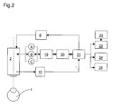
- Fig.2 shows the basic circuit diagram of all components:
- the from Refractometer 20 measured data are via an evaluation and Control unit 21 processed and stored.
- the data output takes place, for example, via a monitor 22
- Patient's eye 1 shown optionally with that from the refractometer measured optical data of the patient's eye and any further patient data.
- These can in turn be made using an image printer 23 or a pure data printer 24 printed or in the Patient file 25 are transmitted.
- the one for the operation necessary patient data are retrieved from the patient file if necessary 25 transferred to the evaluation and control unit 21.
- the evaluation and control unit 21 prepares the data of the video documentation device 10, preferably a digital camera, and provides them via an image reflection device 6 Reflection of data to the surgeon (29) in the microscope image Available.
Landscapes
- Health & Medical Sciences (AREA)
- Life Sciences & Earth Sciences (AREA)
- Surgery (AREA)
- Engineering & Computer Science (AREA)
- General Health & Medical Sciences (AREA)
- Veterinary Medicine (AREA)
- Biomedical Technology (AREA)
- Heart & Thoracic Surgery (AREA)
- Medical Informatics (AREA)
- Molecular Biology (AREA)
- Public Health (AREA)
- Animal Behavior & Ethology (AREA)
- Ophthalmology & Optometry (AREA)
- Biophysics (AREA)
- Physics & Mathematics (AREA)
- Nuclear Medicine, Radiotherapy & Molecular Imaging (AREA)
- Oral & Maxillofacial Surgery (AREA)
- Pathology (AREA)
- Eye Examination Apparatus (AREA)
- Microscoopes, Condenser (AREA)
Abstract
Description
Die Erfindung betrifft ein Ophthalmo-Operationsmikroskop mit einer Vorrichtung zur'in situ'-Ermittlung der optischen Daten eines Patientenauges während der Operation.The invention relates to an ophthalmic surgical microscope with a Device for 'in situ' determination of the optical data of a Patient's eye during surgery.
Bei Trübung oder starker Verformung der Linse eines Patientenauges werden heute üblicherweise die optischen Daten des Auges vor der Opera-tion mittels eines Refraktometers, beispielsweise mit dem 'The Welch Allyn Sure Sight ™' der Fa. Welch Allyn, NY 13153 (US), vergleiche Prospekt SM2275Rev. B, vor der Operation bestimmt. Aufgrund der gewonnenen Ergebnisse wird die Dimension der zu implantierenden IOL (Intra Ocular Lens) bestimmt. Dann wird im Laufe der Operation die IOL ins Auge eingesetzt. Nach dem Heilungsprozess - d.h. einige Tage danach - wird erneut mittels eines Refraktometers gemessen, die verbliebene Restfehlsichtigkeit bestimmt und bei Bedarf mittels einer Brille korrigiert.In the event of clouding or severe deformation of the lens of a patient's eye Today, the optical data of the eye in front of the Operation using a refractometer, for example with the 'The Welch Allyn Sure Sight ™ from Welch Allyn, NY 13153 (US), compare brochure SM2275Rev. B, determined before surgery. Based on the results obtained, the dimension of the implanting IOL (Intra Ocular Lens). Then in the course IOL in the eye of the operation. After the healing process - i.e. a few days later - again using a refractometer measured, the remaining residual ametropia determined and if necessary corrected with glasses.
Der Erfinder erkannte, dass diese bekannten Systeme nachteilig sind in
Bezug auf die folgenden Punkte:
Aufgabe der Erfindung ist es nun, eine Vorrichtung zu schaffen, welche es ermöglicht, die optischen Daten eines Patientenauges während der Operation zu bestimmen, ohne den Operationsvorgang selbst unterbrechen zu müssen.The object of the invention is now to provide a device which it enables the optical data of a patient's eye during the To determine surgery without the operation itself to have to interrupt.
Gelöst wird diese Aufgabe durch die nachfolgend beschriebene Vorrichtung:This task is solved by the following Contraption:
In ein standardmäßiges Operationsmikroskop wird ein Refraktometer (Auto-Refractive-Generator und -Analysator) integriert, welches die Bestimmung der optischen Daten des Patientenauges 'in situ' - d.h. während der Operation - erlaubt. Dies geschieht vorzugsweise auf folgendem Wege:A refractometer is placed in a standard surgical microscope (Auto Refractive Generator and Analyzer) integrated, which the Determination of the optical data of the patient's eye 'in situ' - i.e. during the operation - allowed. This is preferably done on following way:
Das von einem Refraktometer generierte Licht wird über eine Optik und beispielsweise einen Strahlenteiler in den Hauptstrahlengang eines Mikroskops eingespiegelt und auf das Patientenauge projiziert. Das von der Netzhaut des Patientenauges reflektierte Refraktometer-Licht wird wiederum mittels beispielsweise eines Strahlenteilers aus dem Strahlengang des Mikroskops ausgespiegelt und über eine Optik auf eine Analyseeinheit des Refraktometers abgebildet. Das Refraktometer bzw. dessen Auswertungseinheit bestimmt damit laufend die Qualität der Korrektur durch die ins Auge implantierte Linse und teilt dies über ein Display, eine Vorrichtung zur Einspiegelung von Daten und/oder über Signalton/Signallicht dem Operateur mit. Die Ein- und Ausspiegelung der Refraktometer-Strahlengänge erfolgt beispielsweise direkt oberhalb des Zooms oder zwischen dem Zoom und dem Hauptobjektiv. Es lassen sich mit dem Grundprinzip der Erfindung verschiedene Varianten aufbauen.The light generated by a refractometer is transmitted through optics and for example a beam splitter in the main beam path of a Mirrored microscope and projected onto the patient's eye. That from the refractometer light is reflected in the retina of the patient's eye again using, for example, a beam splitter from the Beam path of the microscope mirrored and on an optic an analysis unit of the refractometer mapped. The refractometer or its evaluation unit continuously determines the quality correction by the lens implanted in the eye and communicates this a display, a device for reflecting data and / or to the surgeon via signal tone / signal light. The inputs and The refractometer beam paths are reflected, for example directly above the zoom or between the zoom and the main lens. It can be done with the basic principle of the invention build different variants.
Durch die vorgängig beschriebene Vorrichtung werden die folgenden Verbesserungen erreicht:
- Durch die 'in situ'-Ermittlung der optischen Daten des Patientenauges während der Operation lassen sich durch den Chirurgen frühzeitig Gegenmaßnahmen bei Abweichungen von den Soll-Werten einleiten.
- Durch die frühzeitige Messung und Korrektur von potentiellen Abweichungen lässt sich die übrigbleibende Fehlsichtigkeit nach dem Heilungsprozess minimieren.
- Insgesamt kann damit sowohl die Qualität des Operations-Ergebnisses wie auch die Gefahr einer größeren Abweichung während der Operation auf ein Minimum reduziert werden.
- Gemäß einer Weiterentwicklung der Erfindung kann der Chirurg bei Abweichungen über einem festzulegenden Schwellenwert während der Operation mittels eines Warnmechanismus - beispielsweise eines Signaltons und/oder einer Blinkleuchte und/oder eines Einspiegelungmoduls - auf eine akute Gefahr aufmerksam gemacht werden.
- The 'in situ' determination of the optical data of the patient's eye during the operation enables the surgeon to take countermeasures at an early stage in the event of deviations from the target values.
- By early measurement and correction of potential deviations, the remaining ametropia after the healing process can be minimized.
- Overall, the quality of the operation result as well as the risk of a larger deviation during the operation can be reduced to a minimum.
- According to a further development of the invention, the surgeon can be made aware of an acute danger in the event of deviations above a threshold value to be determined during the operation by means of a warning mechanism - for example a signal tone and / or a flashing light and / or a reflection module.
Anhand von schematischen Zeichnungen wird die Erfindung näher erläutert. Es zeigen dabei:
- Fig.1:
- eine erfindungsgemäße Integration eines Refraktometers in ein Operationsmikroskop;
- Fig.2:
- das prinzipielle Schaltbild aller Komponenten.
- Fig.1:
- an inventive integration of a refractometer in a surgical microscope;
- Figure 2:
- the basic circuit diagram of all components.
Fig.1 zeigt das vom Patientenauge 1 ausgehende Licht, welches über
ein Hauptobjektiv 3 und über einen Zoom 4 auf den Tubus 5 mit
Okularen geleitet wird. Im rechten Hauptstrahlengang des Mikroskops 2
ist beispielsweise zwischen dem Zoom 4 und dem Tubus 5 ein
Strahlenteiler 11 angeordnet, welcher das Licht für eine Video-Dokumentationsvorrichtung
10 ausspiegelt. Im linken
Hauptstrahlengang ist beispielsweise zwischen dem Zoom 4 und dem
Tubus 5 ein Strahlenteiler 7 zur Einspiegelung der von einer
Bildeinspiegelungs-Vorrichtung 6 generierten Daten in den
Betrachtungsbereich des Chirurgen angeordnet. Zusätzlich ist ein von
einer Beleuchtung 8 ausgehender Beleuchtungsstrahlengang 9
ersichtlich, welcher das Licht über einen Strahlenteiler 18 sowie einen
Umlenkspiegel 17 auf das Patientenauge 1 projiziert.1 shows the light emanating from the patient's
Das von einem Refraktometer 20 generierte Licht wird
erfindungsgemäß über eine Optik 19 für den Refraktometer-Strahlengang
12 an der Position A - direkt über dem Zoom 4
gelegen - mittels des Strahlenteilers 13 beispielsweise in den rechten
Hauptstrahlengang des Mikroskops 2 eingeblendet. Dieses Licht wird
über den Zoom 4 und das Hauptobjektiv 3 auf der Hornhaut des
Patientenauges 1 abgebildet. Das von dort reflektierte Refraktometer-Licht
wird wiederum über das Hauptobjektiv 3 und den Zoom 4 auf den
Strahlenteiler 13 geleitet, welcher das Refraktometer-Licht ausspiegelt
und über die Optik 19 für den Refraktometer-Strahlengang 12 zur
Analyse auf die Messeinheit des Refraktometers 20 leitet.The light generated by a
Als Variante wird das Refraktometer-Licht an der Position B, die direkt
über dem Hauptobjektiv 3 liegt, über einen Umlenkspiegel 15 für den
Refraktometer-Strahlengang 14 auf das Patientenauge 1 projiziert und
registriert.As a variant, the refractometer light is at position B, which is direct
lies above the
Als weitere Variante wird das Refraktometer-Licht an der Position C, die
zentral über dem Hauptopjektiv 3 liegt, mittels des Umlenkspiegels 17
für den Refraktometer-Strahlengang 16 und die Beleuchtung 9 mit der
Beleuchtungsoptik 26 auf den Strahlenteiler 18 umgelenkt, welcher den
Beleuchtungsstrahlengang 9 und den Refraktometer-Strahlengang 16
zusammenführt. Der Refraktometer-Strahlengang wird über eine Optik
19 für den Refraktometer-Strahlengang auf das Refraktometer 20
geleitet.As a further variant, the refractometer light is at position C, the
is located centrally above the
Fig.2 zeigt das prinzipielle Schaltbild aller Komponenten: Die vom
Refraktometer 20 gemessenen Daten werden über eine Auswertungsund
Steuereinheit 21 verarbeitet und gespeichert. Die Datenausgabe
erfolgt beispielsweise über einen Monitor 22. Dort wird das
Patientenauge 1 abgebildet, wahlweise mit den vom Refraktometer
gemessenen optischen Daten des Patientenauges und eventueller
weiterer Patientendaten. Diese können wiederum über einen Bildprinter
23 oder einen reinen Datenprinter 24 ausgedruckt oder in die
Patientendatei 25 übermittelt werden. Die für die Operation
notwendigen Patientendaten werden bei Bedarf aus der Patientendatei
25 in die Auswertungs- und Steuereinheit 21 übertragen.Fig.2 shows the basic circuit diagram of all components: The from
Die Auswertungs- und Steuereinheit 21 bereitet die Daten der Video-Dokumentations-Vorrichtung
10, vorzugsweise einer Digital-Kamera,
auf und stellt sie über eine Bildeinspiegelungs-Vorrichtung 6 zur
Einspiegelung von Daten dem Operateur (29) im Mikroskopbild zur
Verfügung.The evaluation and
Mit Hilfe von Shuttern 27 - vgl. Fig. 1 - kann beispielsweise derjenige Beobachterstrahlengang (28), in den die Daten nicht eingespiegelt werden, abgedunkelt werden. Dies ist wahlweise aber auch in demjenigen Strahlengang möglich, in den die Daten eingespiegelt werden. Dies ermöglicht eine bessere und kontrastreichere Datendarstellung. Hierfür bieten sich die Möglichkeiten an, die in den Patentanmeldungen der Anmelderin DE 10118703 und DE 10118702 offenbart ist. With the help of shutters 27 - cf. Fig. 1 - for example, one Observer beam path (28), in which the data is not reflected be darkened. This is optionally also in possible beam path into which the data is reflected become. This enables better and higher contrast Data representation. The options available in the Patent applications of the applicant DE 10118703 and DE 10118702 is disclosed.
- 11
- Patientenaugepatient's eye
- 22
- Operationsmikroskopsurgical microscope
- 33
- Hauptobjektivmain objective
- 44
- Zoomzoom
- 55
- Tubus mit OkularenTube with eyepieces
- 66
- Bildeinspiegelungs-VorrichtungBildeinspiegelungs device
- 77
- Strahlenteiler für (6)Beam splitter for (6)
- 88th
- Beleuchtunglighting
- 99
- BeleuchtungsstrahlengangIllumination beam path
- 1010
- Video-Dokumentations-VorrichtungVideo documentation device
- 1111
- Strahlenteiler für (10)Beam splitter for (10)
- 1212
- Refraktometer-Strahlengang an der Position A (Ein-/Ausspiegelung)Refractometer beam path at position A (mirroring in / out)
- 1313
- Strahlenteiler für (12)Beam splitter for (12)
- 1414
- Refraktometer-Strahlengang an der Position B (Ein-/Ausspiegelung)Refractometer beam path at position B (mirroring in / out)
- 1515
- Umlenkspiegel für (14)Deflecting mirror for (14)
- 1616
- Refraktometer-Strahlengang an der Position C (Ein-/Ausspiegelung)Refractometer beam path at position C (mirroring in / out)
- 1717
- Umlenkspiegel für (16) und (8)Deflecting mirror for (16) and (8)
- 1818
- Strahlenteiler für (16) Beam splitter for (16)
- 1919
- Optik für Refraktometer-Strahlengang (Positionen A, B und/oder C)Optics for refractometer beam path (positions A, B and / or C)
- 2020
- Refraktometerrefractometer
- 2121
- Auswertungs- und SteuereinheitEvaluation and control unit
- 2222
- Monitormonitor
- 2323
- Bildprinterimage Printer
- 2424
- Datenprinterdata Printer
- 2525
- Patientendateipatient file
- 2626
- Beleuchtungsoptikillumination optics
- 2727
- Shutter (Blende(n))Shutter (aperture (s))
- 2828
- (Teil-)Strahlengänge für (29)(Partial) beam paths for (29)
- 2929
- Beobachter (Chirurg)Observer (surgeon)
Claims (12)
Applications Claiming Priority (2)
| Application Number | Priority Date | Filing Date | Title |
|---|---|---|---|
| DE10202509A DE10202509A1 (en) | 2002-01-23 | 2002-01-23 | Ophthalmic surgical microscope |
| DE10202509 | 2002-01-23 |
Publications (2)
| Publication Number | Publication Date |
|---|---|
| EP1338238A2 true EP1338238A2 (en) | 2003-08-27 |
| EP1338238A3 EP1338238A3 (en) | 2004-07-28 |
Family
ID=7712873
Family Applications (1)
| Application Number | Title | Priority Date | Filing Date |
|---|---|---|---|
| EP03001157A Withdrawn EP1338238A3 (en) | 2002-01-23 | 2003-01-21 | Ophthalmic operation microscope |
Country Status (4)
| Country | Link |
|---|---|
| US (1) | US20030139736A1 (en) |
| EP (1) | EP1338238A3 (en) |
| JP (1) | JP2003265515A (en) |
| DE (1) | DE10202509A1 (en) |
Cited By (4)
| Publication number | Priority date | Publication date | Assignee | Title |
|---|---|---|---|---|
| WO2007028564A1 (en) * | 2005-09-07 | 2007-03-15 | Carl Zeiss Surgical Gmbh | Ophthalmic operating microscope comprising a measuring unit |
| DE102010008146A1 (en) | 2010-02-12 | 2011-08-18 | Carl Zeiss Surgical GmbH, 73447 | Measuring system and method for determining the refraction of an eye, the radius of curvature of the cornea or the internal pressure of an eye |
| DE102009053208A1 (en) | 2008-11-06 | 2011-08-18 | Leica Instruments (Singapore) Pte. Ltd. | Device for facilitating eye operation e.g. cataract extraction to treat grey starling of patient and/or intraocular lens replacement, has machine human interface transmitting information for quality assurance of handle to surgeon |
| DE102010015691A1 (en) | 2010-04-21 | 2011-10-27 | Carl Zeiss Microlmaging Gmbh | Observation device for use as comparator for co-observation of e.g. three-dimensional stereoscopic image of patient, has beam combiner arranged downstream of beam splitter for coupling of partial optical path in main optical path |
Families Citing this family (21)
| Publication number | Priority date | Publication date | Assignee | Title |
|---|---|---|---|---|
| US7556378B1 (en) | 2003-04-10 | 2009-07-07 | Tsontcho Ianchulev | Intraoperative estimation of intraocular lens power |
| AU2005234778B2 (en) | 2004-04-20 | 2011-04-21 | Alcon Inc. | Integrated surgical microscope and wavefront sensor |
| US7911689B2 (en) * | 2005-09-22 | 2011-03-22 | Olympus Corporation | Microscope |
| US8820929B2 (en) * | 2006-01-20 | 2014-09-02 | Clarity Medical Systems, Inc. | Real-time measurement/display/record/playback of wavefront data for use in vision correction procedures |
| US7594729B2 (en) | 2007-10-31 | 2009-09-29 | Wf Systems, Llc | Wavefront sensor |
| CH699887A1 (en) * | 2008-11-08 | 2010-05-14 | Leica Instr Singapore Pte Ltd | Method for positioning artificial interocular lens into eye of patient during e.g. cataract extraction, involves positioning artificial interocular lens by adjusting alignment of interocular lens using angular and lateral positions of lens |
| US8550624B2 (en) | 2008-11-06 | 2013-10-08 | Wavetec Vision Systems, Inc. | Optical angular measurement system for ophthalmic applications and method for positioning of a toric intraocular lens with increased accuracy |
| US8876290B2 (en) | 2009-07-06 | 2014-11-04 | Wavetec Vision Systems, Inc. | Objective quality metric for ocular wavefront measurements |
| CN102497833B (en) | 2009-07-14 | 2014-12-03 | 波技术视觉系统公司 | Ophthalmic surgery measurement system |
| EP2453822B1 (en) | 2009-07-14 | 2014-08-20 | WaveTec Vision Systems, Inc. | Determination of the effective lens position of an intraocular lens using aphakic refractive power |
| DE102010016623A1 (en) | 2010-04-23 | 2011-10-27 | Leica Microsystems (Schweiz) Ag | Illumination device for an ophthalmic surgical microscope |
| EP3597100A1 (en) | 2011-12-05 | 2020-01-22 | Bioptigen, Inc. | Optical imaging systems having input beam shape control and path length control |
| US8777412B2 (en) | 2012-04-05 | 2014-07-15 | Bioptigen, Inc. | Surgical microscopes using optical coherence tomography and related methods |
| US9072462B2 (en) | 2012-09-27 | 2015-07-07 | Wavetec Vision Systems, Inc. | Geometric optical power measurement device |
| JP6373366B2 (en) | 2013-06-04 | 2018-08-15 | バイオプティジェン,インコーポレイテッドBioptigen, Inc. | Method of operating scanning beam type system and optical scanning beam type system |
| EP3027151B1 (en) | 2013-07-29 | 2019-09-11 | Bioptigen, Inc. | Procedural optical coherence tomography (oct) for surgery and related systems and methods |
| CN105612453B (en) | 2013-08-28 | 2018-03-27 | 拜尔普泰戈恩公司 | The HUD of surgery microscope is integrated for optical coherence tomography |
| DE102017124548B3 (en) | 2017-10-20 | 2018-07-26 | Carl Zeiss Meditec Ag | Microscope with an OCT device and a wavefront measuring device |
| DE102017124545B3 (en) | 2017-10-20 | 2019-01-24 | Carl Zeiss Meditec Ag | microscope |
| AU2021210962A1 (en) | 2020-01-22 | 2022-08-04 | Photonic Medical Inc. | Open view, multi-modal, calibrated digital loupe with depth sensing |
| DE202020000635U1 (en) | 2020-02-17 | 2020-06-19 | Carl Zeiss Microscopy Gmbh | Binocular digital tube for a microscope |
Citations (6)
| Publication number | Priority date | Publication date | Assignee | Title |
|---|---|---|---|---|
| US5249004A (en) * | 1989-12-28 | 1993-09-28 | Kabushiki Kaisha Topcon | Microscope for an operation |
| DE4310561A1 (en) * | 1993-03-26 | 1994-09-29 | Klaus Prof Dipl Phys Dietrich | Device and method of determining the visual acuity and refraction, and for observation of the eye surface |
| US5576780A (en) * | 1992-05-26 | 1996-11-19 | Cain Research Pty. Ltd. | Method for evaluation of length of focus of the eye |
| WO2000019885A1 (en) * | 1998-10-07 | 2000-04-13 | Tracey Technologies, L.L.C. | Device for measuring aberration refraction of the eye |
| WO2001027659A2 (en) * | 1999-10-13 | 2001-04-19 | Leica Microsystems Ag | Stereo operating microscope comprising a single-mirror device providing information |
| US6304372B1 (en) * | 1995-05-17 | 2001-10-16 | Leica Microsystems Ag | Microscope including a fade-in element and related method of using a microscope |
Family Cites Families (7)
| Publication number | Priority date | Publication date | Assignee | Title |
|---|---|---|---|---|
| DE2643344A1 (en) * | 1976-09-25 | 1978-03-30 | Zeiss Carl Fa | DEVICE FOR DETERMINING CORNEAL TASTIGMATISM IN THE HUMAN EYE |
| US4544243A (en) * | 1984-05-24 | 1985-10-01 | Cooper Lasersonics, Inc. | Heads up display for microscope using remotely controlled instrument |
| JPS62268523A (en) * | 1986-05-17 | 1987-11-21 | キヤノン株式会社 | Ophthalmic apparatus |
| JPH09135811A (en) * | 1995-11-15 | 1997-05-27 | Nikon Corp | Ophthalmic device |
| US6193710B1 (en) * | 1998-07-16 | 2001-02-27 | Visx, Incorporated | Method for scanning non-overlapping patterns of laser energy with diffractive optics |
| US6419671B1 (en) * | 1999-12-23 | 2002-07-16 | Visx, Incorporated | Optical feedback system for vision correction |
| US6550917B1 (en) * | 2000-02-11 | 2003-04-22 | Wavefront Sciences, Inc. | Dynamic range extension techniques for a wavefront sensor including use in ophthalmic measurement |
-
2002
- 2002-01-23 DE DE10202509A patent/DE10202509A1/en not_active Withdrawn
-
2003
- 2003-01-13 US US10/341,111 patent/US20030139736A1/en not_active Abandoned
- 2003-01-21 EP EP03001157A patent/EP1338238A3/en not_active Withdrawn
- 2003-01-23 JP JP2003014499A patent/JP2003265515A/en not_active Withdrawn
Patent Citations (6)
| Publication number | Priority date | Publication date | Assignee | Title |
|---|---|---|---|---|
| US5249004A (en) * | 1989-12-28 | 1993-09-28 | Kabushiki Kaisha Topcon | Microscope for an operation |
| US5576780A (en) * | 1992-05-26 | 1996-11-19 | Cain Research Pty. Ltd. | Method for evaluation of length of focus of the eye |
| DE4310561A1 (en) * | 1993-03-26 | 1994-09-29 | Klaus Prof Dipl Phys Dietrich | Device and method of determining the visual acuity and refraction, and for observation of the eye surface |
| US6304372B1 (en) * | 1995-05-17 | 2001-10-16 | Leica Microsystems Ag | Microscope including a fade-in element and related method of using a microscope |
| WO2000019885A1 (en) * | 1998-10-07 | 2000-04-13 | Tracey Technologies, L.L.C. | Device for measuring aberration refraction of the eye |
| WO2001027659A2 (en) * | 1999-10-13 | 2001-04-19 | Leica Microsystems Ag | Stereo operating microscope comprising a single-mirror device providing information |
Cited By (9)
| Publication number | Priority date | Publication date | Assignee | Title |
|---|---|---|---|---|
| WO2007028564A1 (en) * | 2005-09-07 | 2007-03-15 | Carl Zeiss Surgical Gmbh | Ophthalmic operating microscope comprising a measuring unit |
| DE102009053208A1 (en) | 2008-11-06 | 2011-08-18 | Leica Instruments (Singapore) Pte. Ltd. | Device for facilitating eye operation e.g. cataract extraction to treat grey starling of patient and/or intraocular lens replacement, has machine human interface transmitting information for quality assurance of handle to surgeon |
| DE102009053208B4 (en) | 2008-11-06 | 2022-05-19 | Leica Instruments (Singapore) Pte. Ltd. | Device for monitoring the implantation of an IOL (orientation monitoring) |
| DE102010008146A1 (en) | 2010-02-12 | 2011-08-18 | Carl Zeiss Surgical GmbH, 73447 | Measuring system and method for determining the refraction of an eye, the radius of curvature of the cornea or the internal pressure of an eye |
| US10080493B2 (en) | 2010-02-12 | 2018-09-25 | Carl Zeiss Meditec Ag | Measurement system and method for establishing the refraction of an eye, the radius of curvature of the cornea or the internal pressure of an eye |
| US11039743B2 (en) | 2010-02-12 | 2021-06-22 | Carl Zeiss Meditec Ag | Measurement system and method for establishing the refraction of an eye, the radius of curvature of the cornea or the internal pressure of an eye |
| US11039744B2 (en) | 2010-02-12 | 2021-06-22 | Carl Zeiss Meditec Ag | Measurement system and method for establishing the refraction of an eye, the radius of curvature of the cornea or the internal pressure of an eye |
| DE102010008146B4 (en) | 2010-02-12 | 2022-03-31 | Carl Zeiss Meditec Ag | Measuring system and method for determining the intraocular pressure and method and system for adjusting the intraocular pressure |
| DE102010015691A1 (en) | 2010-04-21 | 2011-10-27 | Carl Zeiss Microlmaging Gmbh | Observation device for use as comparator for co-observation of e.g. three-dimensional stereoscopic image of patient, has beam combiner arranged downstream of beam splitter for coupling of partial optical path in main optical path |
Also Published As
| Publication number | Publication date |
|---|---|
| EP1338238A3 (en) | 2004-07-28 |
| DE10202509A1 (en) | 2003-07-31 |
| US20030139736A1 (en) | 2003-07-24 |
| JP2003265515A (en) | 2003-09-24 |
Similar Documents
| Publication | Publication Date | Title |
|---|---|---|
| EP1338238A2 (en) | Ophthalmic operation microscope | |
| JP5248926B2 (en) | Eye refractive power measuring device | |
| DE102010008146A1 (en) | Measuring system and method for determining the refraction of an eye, the radius of curvature of the cornea or the internal pressure of an eye | |
| DE60115126T2 (en) | Fundus camera with visible and invisible illumination | |
| DE102005032501A1 (en) | Instrument for the examination of a patient's eye combines the functions of a slit lamp and an ophthalmoscope, to examine the eye structure from the front to the back | |
| DE102011088038B4 (en) | Surgical microscope system for ophthalmology and associated detection unit | |
| DE10242983B4 (en) | Ophthalmic surgical microscope with object illumination | |
| DE10302401A1 (en) | surgical microscope | |
| DE19731301C2 (en) | Device for controlling a microscope by means of gaze direction analysis | |
| DE102006061932A1 (en) | Arrangement of ophthalmic devices for improving fundus images | |
| DE19502337C2 (en) | Device and method for testing visual functions | |
| EP1396747A1 (en) | Illumination for a surgical microscope in order to protect human tissue | |
| DE2544561A1 (en) | Ophthalmoscope or fundus camera with fibre optic illumination= - and only indirect illumination of the entrance pupil | |
| WO2009143976A1 (en) | Optical system for ophthalmology appliances, in particular fundus cameras | |
| DE10314944A1 (en) | Illumination and radiation unit for ophthalmic devices | |
| WO2005039404A1 (en) | Illumination unit for fundus cameras and/or ophthalmoscopes | |
| DE102017105580A1 (en) | surgical microscope | |
| JP2006330040A (en) | Observation apparatus | |
| DE202010008225U1 (en) | Optical instrument with diopter correction | |
| DE3338400A1 (en) | VISUALITY EXAMINER | |
| DE3124305C2 (en) | Device for observing the fundus | |
| DE10009532A1 (en) | Quality assurance method for eye operations involves using binocular observation instrument to observe surface of eye and test card projected onto retina through eye lens | |
| DE102006053581B4 (en) | Refractive treatment device with slit illumination | |
| DE102007036683B4 (en) | Apparatus and method for automatically focusing a non-mydriatic fundus camera | |
| DE102021107297A1 (en) | Optical system for eye surgery and method for avoiding excessive light intensity on a digital image sensor of a surgical microscope |
Legal Events
| Date | Code | Title | Description |
|---|---|---|---|
| PUAI | Public reference made under article 153(3) epc to a published international application that has entered the european phase |
Free format text: ORIGINAL CODE: 0009012 |
|
| AK | Designated contracting states |
Designated state(s): AT BE BG CH CY CZ DE DK EE ES FI FR GB GR HU IE IT LI LU MC NL PT SE SI SK TR |
|
| AX | Request for extension of the european patent |
Extension state: AL LT LV MK RO |
|
| RIC1 | Information provided on ipc code assigned before grant |
Ipc: 7A 61B 3/103 B Ipc: 7A 61B 19/00 B Ipc: 7A 61B 3/13 A |
|
| PUAL | Search report despatched |
Free format text: ORIGINAL CODE: 0009013 |
|
| RIC1 | Information provided on ipc code assigned before grant |
Ipc: 7G 02B 21/18 B Ipc: 7A 61B 3/103 B Ipc: 7A 61B 19/00 B Ipc: 7A 61B 3/13 A |
|
| AK | Designated contracting states |
Kind code of ref document: A3 Designated state(s): AT BE BG CH CY CZ DE DK EE ES FI FR GB GR HU IE IT LI LU MC NL PT SE SI SK TR |
|
| AX | Request for extension of the european patent |
Extension state: AL LT LV MK RO |
|
| 17P | Request for examination filed |
Effective date: 20050128 |
|
| AKX | Designation fees paid |
Designated state(s): CH DE FR GB LI |
|
| STAA | Information on the status of an ep patent application or granted ep patent |
Free format text: STATUS: THE APPLICATION IS DEEMED TO BE WITHDRAWN |
|
| 18D | Application deemed to be withdrawn |
Effective date: 20060707 |