EP1338193A1 - Dispositif de fixation de fil, notamment pour un piquet de vigne - Google Patents
Dispositif de fixation de fil, notamment pour un piquet de vigne Download PDFInfo
- Publication number
- EP1338193A1 EP1338193A1 EP03290329A EP03290329A EP1338193A1 EP 1338193 A1 EP1338193 A1 EP 1338193A1 EP 03290329 A EP03290329 A EP 03290329A EP 03290329 A EP03290329 A EP 03290329A EP 1338193 A1 EP1338193 A1 EP 1338193A1
- Authority
- EP
- European Patent Office
- Prior art keywords
- wire
- stake
- vine
- profiled
- take
- Prior art date
- Legal status (The legal status is an assumption and is not a legal conclusion. Google has not performed a legal analysis and makes no representation as to the accuracy of the status listed.)
- Granted
Links
Images

Classifications
-
- E—FIXED CONSTRUCTIONS
- E04—BUILDING
- E04H—BUILDINGS OR LIKE STRUCTURES FOR PARTICULAR PURPOSES; SWIMMING OR SPLASH BATHS OR POOLS; MASTS; FENCING; TENTS OR CANOPIES, IN GENERAL
- E04H17/00—Fencing, e.g. fences, enclosures, corrals
- E04H17/02—Wire fencing, e.g. made of wire mesh
- E04H17/10—Wire fencing, e.g. made of wire mesh characterised by the way of connecting wire to posts; Droppers
- E04H17/124—Wire fencing, e.g. made of wire mesh characterised by the way of connecting wire to posts; Droppers connecting by one or more clamps, clips, screws, wedges or ties
-
- A—HUMAN NECESSITIES
- A01—AGRICULTURE; FORESTRY; ANIMAL HUSBANDRY; HUNTING; TRAPPING; FISHING
- A01G—HORTICULTURE; CULTIVATION OF VEGETABLES, FLOWERS, RICE, FRUIT, VINES, HOPS OR SEAWEED; FORESTRY; WATERING
- A01G17/00—Cultivation of hops, vines, fruit trees, or like trees
- A01G17/04—Supports for hops, vines, or trees
- A01G17/06—Trellis-work
Definitions
- the invention relates to a wire fixing device, in particular to wire fixation on a vine stake.
- the invention is particularly useful in its application to the fixing of wire vineyard fence.
- the vines are usually planted in parallel lines, so that align the vine branches by training them on a trellising system comprising stakes regularly spaced supporting fixed wires and lifting wires.
- These trellises can be carried out using generally round wooden stakes, or using profiled stakes, generally of constant section.
- Profiled posts include hot-rolled metal posts or cold sections and having a constant section in L, in T in C or in ⁇ or in a another shape having an edge of substantially constant thickness; and understand stakes made of plastic material having an L, C, ⁇ or in another form having an edge of substantially constant thickness.
- An object of the invention is to provide a new means of fixing wire on profiled stakes made of metal or plastic.
- Another object of the invention is to simplify the fixing of wire while keeping the advantages of the known technique and by providing a new means of attachment simple and economical take-up wire.
- the subject of the invention is a device for fixing a wire, in particular a wire on profiled vine stake having a free edge, said device having a end of take-up wire support or fixed wire support, characterized by the fact that the device comprises means for pinching said free edge of the stake vine profile.
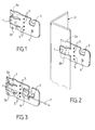
- a device according to the invention comprises a end intended to be fixed on the P profile or vine stake and another end intended to support a fixed wire or a take-up wire.
- the end intended to be fixed to the stake P has substantially a shape pliers with a central jaw 1 and two lateral jaws 2a, 2b, intended for grip the edge of the profile or stake P of the vine, preferably applying pressure elastic on it.
- the other end of the device has a wire receiving conformation 3 take-up, for example in the form of a hook and an orifice 4 for the passage of fixed wire.
- a weakening line 5 allowing folding of one end of the device by relative to the other can advantageously be provided to orient the end of wire reception in relation to stake P.
- This line of weakening 5 can be constituted by aligned holes facilitating manual folding of the device.
- FIG. 3 another embodiment of the device according to the invention comprises elements identical or functionally equivalent to elements of the device of FIGS. 1 and 2, identified by reference numbers identical.
- the device of figure 3 differs from the device of figure 1 by the presence a holding tab 6 for the passage of a take-up wire F.
- Figure 4 shows a device according to the invention mounted on a profile having a T-section
- Figure 5 shows a device according to the invention mounted on a C-shaped profile
- the 6 shows a device according to the invention mounted on a device having a section in ⁇ .
- another device has a clamp-like end with a larger jaw 11 and two smaller width tabs 12a, 12b, as well as a thread receiving notch 13 take-up, a fixed wire passage orifice 14, and a weakening line 15 allowing the bending of the wire support end relative to the end of fixing on the stake.
- the device further comprises a striking surface 16 allowing the use a hammer for securing the clamp comprising the elements 11, 12a, 12b on a vine stake not shown.
- This striking surface device 16 allows rapid attachment to any stake dimension.
- FIG. 8 another device according to the invention comprises elements identical or similar to the elements in FIG. 7 and identified by identical reference figures.
- the device of FIG. 8 comprises a non-return harpoon 19a or 19b produced by cutting on each tab 12a or 12b, so as to obtain a hooking more effective on a stake edge.
- the device of Figure 8 also has a wire receiving portion orientable with respect to the fixing part on the stake, so as to grip the device by this wire receiving part for striking the striking surface 16 during insertion on a stake edge not shown.
- the wire receiving part may include a tongue 17 for holding take-up wire similar to the tongue 6 of the device of FIG. 3.
- each embodiment described can include one or more non-return harpoons such as the non-return harpoons 19a or 19b in FIG. 8.
Landscapes
- Engineering & Computer Science (AREA)
- Architecture (AREA)
- Life Sciences & Earth Sciences (AREA)
- Civil Engineering (AREA)
- Structural Engineering (AREA)
- Botany (AREA)
- Environmental Sciences (AREA)
- Catching Or Destruction (AREA)
- Basic Packing Technique (AREA)
- Toys (AREA)
Abstract
Description
- lesdits moyens de pincement sont disposés à l'opposé de l'extrémité de support de fil releveur ou de maintien de fil fixe,
- des moyens de pincement peuvent comporter des harpons anti-retour,
- lesdits moyens de pincement comportent deux mâchoires aptes à enserrer le bord de piquet profilé de vigne,
- le dispositif comporte une ligne d'affaiblissement pour faciliter le pliage de l'extrémité de support ou de maintien,
- le dispositif comporte une surface de frappe permettant son enfoncement au marteau,
- le dispositif vient de matière d'un seul tenant et est fabriqué en un matériau métallique présentant de bonnes propriétés élastiques,
- le dispositif est réalisé par découpe, pliage ou mise en forme de feuillard métallique.
- La figure 1 représente schématiquement une vue en perspective d'un dispositif selon l'invention.
- La figure 2 représente schématiquement, une vue en perspective d'un dispositif selon l'invention assemblé à un piquet en forme de cornière.
- La figure 3 représente schématiquement, un autre mode de réalisation de dispositif selon l'invention.
- Les figures 4 à 6 représentent schématiquement, des vues en perspective de dispositif selon l'invention assemblé à des piquets profilés de différentes sections.
- la figure 7 représente schématiquement, un mode de réalisation préféré de l'invention.
- la figure 8 représente schématiquement une vue en perspective d'un autre mode de réalisation de dispositif selon l'invention.
Claims (7)
- Dispositif de fixation de fil, notamment de fil sur piquet profilé (P) de vigne comportant un bord libre, ledit dispositif présentant une extrémité de support (3) de fil releveur ou de maintien (4) de fil fixe, le dispositif comportant des moyens de pincement dudit bord libre de piquet profilé de vigne, caractérisé par le fait que lesdits moyens de pincement (1, 2b ; 11, 12a,12b) sont disposés à l'opposé de l'extrémité de support (3) de fil releveur ou de maintien de fil fixe.
- Dispositif selon la revendication 1, caractérisé par le fait que les moyens de pincement (12a, 12b) comportent un ou plusieurs harpon(s) anti-retour (19a, 19b).
- Dispositif selon la revendication 1 ou la revendication 2, caractérisé par le fait que lesdits moyens de pincement (1, 2a, 2b ; 11, 12a, 12b) comportent deux mâchoires (1, 2a, 2b ; 11, 12a, 12b) aptes à enserrer le bord de piquet profilé (P) de vigne.
- Dispositif selon l'une quelconque des revendications 1 à 3, caractérisé par le fait que le dispositif comporte une ligne (5) d'affaiblissement pour faciliter le pliage de l'extrémité de support ou de maintien.
- Dispositif selon l'une quelconque des revendications précédentes, caractérisé par le fait que le dispositif comporte une surface de frappe (16) permettant son enfoncement au marteau.
- Dispositif selon l'une quelconque des revendications précédentes, caractérisé par le fait que le dispositif vient de matière d'un seul tenant et est fabriqué en un matériau métallique présentant de bonnes propriétés élastiques.
- Dispositif selon la revendication 6, caractérisé par le fait que le dispositif est réalisé par découpe, pliage ou mise en forme de feuillard métallique.
Applications Claiming Priority (2)
| Application Number | Priority Date | Filing Date | Title |
|---|---|---|---|
| FR0202191A FR2836006B1 (fr) | 2002-02-21 | 2002-02-21 | Dispositif de fixation de fil, notamment de fixation de fil sur un piquet de vigne |
| FR0202191 | 2002-02-21 |
Publications (2)
| Publication Number | Publication Date |
|---|---|
| EP1338193A1 true EP1338193A1 (fr) | 2003-08-27 |
| EP1338193B1 EP1338193B1 (fr) | 2007-01-17 |
Family
ID=27636376
Family Applications (1)
| Application Number | Title | Priority Date | Filing Date |
|---|---|---|---|
| EP03290329A Expired - Lifetime EP1338193B1 (fr) | 2002-02-21 | 2003-02-11 | Dispositif de fixation de fil, notamment pour un piquet de vigne |
Country Status (3)
| Country | Link |
|---|---|
| EP (1) | EP1338193B1 (fr) |
| DE (1) | DE60311159D1 (fr) |
| FR (1) | FR2836006B1 (fr) |
Cited By (2)
| Publication number | Priority date | Publication date | Assignee | Title |
|---|---|---|---|---|
| GB2535605A (en) * | 2014-12-23 | 2016-08-24 | Gripple Ltd | Improvements in or relating to clamping devices |
| EP2467009B1 (fr) * | 2009-08-21 | 2018-11-07 | Onesteel Wire PTY Limited | Système de montage pour montant |
Citations (7)
| Publication number | Priority date | Publication date | Assignee | Title |
|---|---|---|---|---|
| US1454254A (en) * | 1922-07-10 | 1923-05-08 | Roney Robert Lee | Clip for fastening wire fence fabrics to posts, etc. |
| US4346871A (en) * | 1978-05-10 | 1982-08-31 | Mauduit Francois M | Structure for affixing metallic wire to support posts |
| FR2566064A1 (fr) * | 1984-02-20 | 1985-12-20 | Paoletti Louis | Cavalier pour porter et guider ou fixer un fil sur un bord de paroi |
| EP0072420B1 (fr) * | 1981-08-05 | 1986-01-29 | Manfred Gebhardt | Dispositif de support de fils tendus pour l'utilisation en viticulture et en fruticulture |
| US4982932A (en) * | 1988-08-15 | 1991-01-08 | Wayne Baker | Fence clip assembly |
| FR2686640A1 (fr) * | 1992-01-29 | 1993-07-30 | Villanova Michel | Dispositif de pose et de fixation d'elements filiformes sur des montants verticaux afin de constituer des clotures, grillages, separations et autres. |
| US6050549A (en) * | 1998-02-03 | 2000-04-18 | Foy; Bill D. | Fence clip system |
Family Cites Families (2)
| Publication number | Priority date | Publication date | Assignee | Title |
|---|---|---|---|---|
| FR2820610B1 (fr) * | 2001-02-09 | 2003-08-15 | Alain Fidler | Ensemble pour le palissage, notamment des vignes |
| FR2820609B1 (fr) * | 2001-02-09 | 2003-09-26 | Alain Perchat | Dispositif ecarteur mobile auto repositionnable pour fils releveurs et piquet pour supporter un dispositif |
-
2002
- 2002-02-21 FR FR0202191A patent/FR2836006B1/fr not_active Expired - Fee Related
-
2003
- 2003-02-11 EP EP03290329A patent/EP1338193B1/fr not_active Expired - Lifetime
- 2003-02-11 DE DE60311159T patent/DE60311159D1/de not_active Expired - Fee Related
Patent Citations (7)
| Publication number | Priority date | Publication date | Assignee | Title |
|---|---|---|---|---|
| US1454254A (en) * | 1922-07-10 | 1923-05-08 | Roney Robert Lee | Clip for fastening wire fence fabrics to posts, etc. |
| US4346871A (en) * | 1978-05-10 | 1982-08-31 | Mauduit Francois M | Structure for affixing metallic wire to support posts |
| EP0072420B1 (fr) * | 1981-08-05 | 1986-01-29 | Manfred Gebhardt | Dispositif de support de fils tendus pour l'utilisation en viticulture et en fruticulture |
| FR2566064A1 (fr) * | 1984-02-20 | 1985-12-20 | Paoletti Louis | Cavalier pour porter et guider ou fixer un fil sur un bord de paroi |
| US4982932A (en) * | 1988-08-15 | 1991-01-08 | Wayne Baker | Fence clip assembly |
| FR2686640A1 (fr) * | 1992-01-29 | 1993-07-30 | Villanova Michel | Dispositif de pose et de fixation d'elements filiformes sur des montants verticaux afin de constituer des clotures, grillages, separations et autres. |
| US6050549A (en) * | 1998-02-03 | 2000-04-18 | Foy; Bill D. | Fence clip system |
Cited By (4)
| Publication number | Priority date | Publication date | Assignee | Title |
|---|---|---|---|---|
| EP2467009B1 (fr) * | 2009-08-21 | 2018-11-07 | Onesteel Wire PTY Limited | Système de montage pour montant |
| GB2535605A (en) * | 2014-12-23 | 2016-08-24 | Gripple Ltd | Improvements in or relating to clamping devices |
| GB2535605B (en) * | 2014-12-23 | 2018-04-18 | Gripple Ltd | Clamping devices for retaining elongate members on support arrangements |
| US10631472B2 (en) | 2014-12-23 | 2020-04-28 | Gripple Limited | Clamping devices |
Also Published As
| Publication number | Publication date |
|---|---|
| DE60311159D1 (de) | 2007-03-08 |
| FR2836006A1 (fr) | 2003-08-22 |
| FR2836006B1 (fr) | 2004-07-09 |
| EP1338193B1 (fr) | 2007-01-17 |
Similar Documents
| Publication | Publication Date | Title |
|---|---|---|
| EP0876756A1 (fr) | Ecarteur pour relevage de vigne | |
| FR2714707A1 (fr) | Attache réglable. | |
| FR2540169A1 (fr) | Piquet de palissage | |
| EP3599821B1 (fr) | Dispositif d'accrochage de fils pour les vignes | |
| FR2820610A1 (fr) | Ensemble pour le palissage, notamment des vignes | |
| FR2979400A1 (fr) | Structure de fixation utilisant des pinces | |
| EP1338193B1 (fr) | Dispositif de fixation de fil, notamment pour un piquet de vigne | |
| FR2930303A1 (fr) | Assemblage de colliers autoserrants pour la liaison de pieces,colliers autoserrants correspondants et application de cet assemblage | |
| EP3231729B1 (fr) | Collier de serrage | |
| EP1342405B1 (fr) | Dispositif de fixation de fil, notamment de fil de vigne | |
| FR2731583A1 (fr) | Lien pour arbre fruitier palisse | |
| FR2834860A1 (fr) | Attache pour realiser des arcures de branches d'arbres fruitiers | |
| EP0118322B1 (fr) | Attache perfectionnée formant écrou | |
| EP1065333B1 (fr) | Dispositif de fixation de fil | |
| FR2880927A1 (fr) | Element elastique de fixation et ensemble coherent de tels elements | |
| FR2825576A1 (fr) | Dispositif d'accrochage de l'extremite d'un fil de palissage | |
| CH571617A5 (en) | Mounting and fixation of textile screen - involves posts with parallel rotatable rails each receiving adjacent panel ends | |
| FR2799611A1 (fr) | Dispositif de maintien pour fils de palissage et plus particulierement pour fil de pieds | |
| FR2981415A3 (fr) | Element de lien pour fixer ensemble deux corps oblongs. | |
| FR2844846A3 (fr) | Structure perfectionnee de boulon antivol | |
| FR2810501A1 (fr) | Dispositif d'accrochage des extremites des fils de palissage dits fils releveurs | |
| FR3018156A1 (fr) | Piece de fixation de tuteur sur un fil | |
| FR2518868A1 (fr) | Dispositif de fixation, entre un fil de fer tendu horizontalement et le sol, de ficelles verticales destinees a servir de tuteurs a des plantes grimpantes | |
| FR2898768A1 (fr) | Dispositif de piquet et ecarteur pour le palissage de la vigne | |
| FR2890528A1 (fr) | Attache de maintien pour pieds de vigne |
Legal Events
| Date | Code | Title | Description |
|---|---|---|---|
| PUAI | Public reference made under article 153(3) epc to a published international application that has entered the european phase |
Free format text: ORIGINAL CODE: 0009012 |
|
| AK | Designated contracting states |
Designated state(s): AT BE BG CH CY CZ DE DK EE ES FI FR GB GR HU IE IT LI LU MC NL PT SE SI SK TR |
|
| AX | Request for extension of the european patent |
Extension state: AL LT LV MK RO |
|
| 17P | Request for examination filed |
Effective date: 20031105 |
|
| AKX | Designation fees paid |
Designated state(s): AT BE BG CH CY CZ DE DK EE ES FI FR GB GR HU IE IT LI LU MC NL PT SE SI SK TR |
|
| GRAP | Despatch of communication of intention to grant a patent |
Free format text: ORIGINAL CODE: EPIDOSNIGR1 |
|
| GRAS | Grant fee paid |
Free format text: ORIGINAL CODE: EPIDOSNIGR3 |
|
| GRAA | (expected) grant |
Free format text: ORIGINAL CODE: 0009210 |
|
| AK | Designated contracting states |
Kind code of ref document: B1 Designated state(s): AT BE BG CH CY CZ DE DK EE ES FI FR GB GR HU IE IT LI LU MC NL PT SE SI SK TR |
|
| PG25 | Lapsed in a contracting state [announced via postgrant information from national office to epo] |
Ref country code: FI Free format text: LAPSE BECAUSE OF FAILURE TO SUBMIT A TRANSLATION OF THE DESCRIPTION OR TO PAY THE FEE WITHIN THE PRESCRIBED TIME-LIMIT Effective date: 20070117 Ref country code: IE Free format text: LAPSE BECAUSE OF FAILURE TO SUBMIT A TRANSLATION OF THE DESCRIPTION OR TO PAY THE FEE WITHIN THE PRESCRIBED TIME-LIMIT Effective date: 20070117 Ref country code: AT Free format text: LAPSE BECAUSE OF FAILURE TO SUBMIT A TRANSLATION OF THE DESCRIPTION OR TO PAY THE FEE WITHIN THE PRESCRIBED TIME-LIMIT Effective date: 20070117 Ref country code: SI Free format text: LAPSE BECAUSE OF FAILURE TO SUBMIT A TRANSLATION OF THE DESCRIPTION OR TO PAY THE FEE WITHIN THE PRESCRIBED TIME-LIMIT Effective date: 20070117 Ref country code: NL Free format text: LAPSE BECAUSE OF FAILURE TO SUBMIT A TRANSLATION OF THE DESCRIPTION OR TO PAY THE FEE WITHIN THE PRESCRIBED TIME-LIMIT Effective date: 20070117 Ref country code: DK Free format text: LAPSE BECAUSE OF FAILURE TO SUBMIT A TRANSLATION OF THE DESCRIPTION OR TO PAY THE FEE WITHIN THE PRESCRIBED TIME-LIMIT Effective date: 20070117 |
|
| REG | Reference to a national code |
Ref country code: GB Ref legal event code: FG4D Free format text: NOT ENGLISH |
|
| REG | Reference to a national code |
Ref country code: CH Ref legal event code: EP |
|
| PG25 | Lapsed in a contracting state [announced via postgrant information from national office to epo] |
Ref country code: CH Free format text: LAPSE BECAUSE OF NON-PAYMENT OF DUE FEES Effective date: 20070228 Ref country code: LI Free format text: LAPSE BECAUSE OF NON-PAYMENT OF DUE FEES Effective date: 20070228 Ref country code: MC Free format text: LAPSE BECAUSE OF NON-PAYMENT OF DUE FEES Effective date: 20070228 |
|
| REG | Reference to a national code |
Ref country code: IE Ref legal event code: FG4D Free format text: LANGUAGE OF EP DOCUMENT: FRENCH |
|
| REF | Corresponds to: |
Ref document number: 60311159 Country of ref document: DE Date of ref document: 20070308 Kind code of ref document: P |
|
| PG25 | Lapsed in a contracting state [announced via postgrant information from national office to epo] |
Ref country code: SE Free format text: LAPSE BECAUSE OF FAILURE TO SUBMIT A TRANSLATION OF THE DESCRIPTION OR TO PAY THE FEE WITHIN THE PRESCRIBED TIME-LIMIT Effective date: 20070417 |
|
| PG25 | Lapsed in a contracting state [announced via postgrant information from national office to epo] |
Ref country code: BG Free format text: LAPSE BECAUSE OF EXPIRATION OF PROTECTION Effective date: 20070418 |
|
| PG25 | Lapsed in a contracting state [announced via postgrant information from national office to epo] |
Ref country code: ES Free format text: LAPSE BECAUSE OF FAILURE TO SUBMIT A TRANSLATION OF THE DESCRIPTION OR TO PAY THE FEE WITHIN THE PRESCRIBED TIME-LIMIT Effective date: 20070428 |
|
| PG25 | Lapsed in a contracting state [announced via postgrant information from national office to epo] |
Ref country code: PT Free format text: LAPSE BECAUSE OF FAILURE TO SUBMIT A TRANSLATION OF THE DESCRIPTION OR TO PAY THE FEE WITHIN THE PRESCRIBED TIME-LIMIT Effective date: 20070618 |
|
| NLV1 | Nl: lapsed or annulled due to failure to fulfill the requirements of art. 29p and 29m of the patents act | ||
| GBV | Gb: ep patent (uk) treated as always having been void in accordance with gb section 77(7)/1977 [no translation filed] |
Effective date: 20070117 |
|
| REG | Reference to a national code |
Ref country code: IE Ref legal event code: FD4D |
|
| REG | Reference to a national code |
Ref country code: CH Ref legal event code: PL |
|
| PLBE | No opposition filed within time limit |
Free format text: ORIGINAL CODE: 0009261 |
|
| STAA | Information on the status of an ep patent application or granted ep patent |
Free format text: STATUS: NO OPPOSITION FILED WITHIN TIME LIMIT |
|
| PG25 | Lapsed in a contracting state [announced via postgrant information from national office to epo] |
Ref country code: GB Free format text: LAPSE BECAUSE OF FAILURE TO SUBMIT A TRANSLATION OF THE DESCRIPTION OR TO PAY THE FEE WITHIN THE PRESCRIBED TIME-LIMIT Effective date: 20070117 Ref country code: SK Free format text: LAPSE BECAUSE OF FAILURE TO SUBMIT A TRANSLATION OF THE DESCRIPTION OR TO PAY THE FEE WITHIN THE PRESCRIBED TIME-LIMIT Effective date: 20070117 |
|
| 26N | No opposition filed |
Effective date: 20071018 |
|
| BERE | Be: lapsed |
Owner name: THEVENIN, PATRICK Effective date: 20070228 Owner name: GISSINGER, JEAN-EDOUARD Effective date: 20070228 Owner name: THEVENIN, STEPHANE Effective date: 20070228 |
|
| PG25 | Lapsed in a contracting state [announced via postgrant information from national office to epo] |
Ref country code: BE Free format text: LAPSE BECAUSE OF NON-PAYMENT OF DUE FEES Effective date: 20070228 Ref country code: CZ Free format text: LAPSE BECAUSE OF FAILURE TO SUBMIT A TRANSLATION OF THE DESCRIPTION OR TO PAY THE FEE WITHIN THE PRESCRIBED TIME-LIMIT Effective date: 20070117 |
|
| PG25 | Lapsed in a contracting state [announced via postgrant information from national office to epo] |
Ref country code: DE Free format text: LAPSE BECAUSE OF NON-PAYMENT OF DUE FEES Effective date: 20070901 |
|
| PG25 | Lapsed in a contracting state [announced via postgrant information from national office to epo] |
Ref country code: GR Free format text: LAPSE BECAUSE OF FAILURE TO SUBMIT A TRANSLATION OF THE DESCRIPTION OR TO PAY THE FEE WITHIN THE PRESCRIBED TIME-LIMIT Effective date: 20070418 Ref country code: IT Free format text: LAPSE BECAUSE OF FAILURE TO SUBMIT A TRANSLATION OF THE DESCRIPTION OR TO PAY THE FEE WITHIN THE PRESCRIBED TIME-LIMIT Effective date: 20070117 |
|
| PG25 | Lapsed in a contracting state [announced via postgrant information from national office to epo] |
Ref country code: EE Free format text: LAPSE BECAUSE OF FAILURE TO SUBMIT A TRANSLATION OF THE DESCRIPTION OR TO PAY THE FEE WITHIN THE PRESCRIBED TIME-LIMIT Effective date: 20070117 |
|
| PG25 | Lapsed in a contracting state [announced via postgrant information from national office to epo] |
Ref country code: CY Free format text: LAPSE BECAUSE OF FAILURE TO SUBMIT A TRANSLATION OF THE DESCRIPTION OR TO PAY THE FEE WITHIN THE PRESCRIBED TIME-LIMIT Effective date: 20070117 |
|
| PG25 | Lapsed in a contracting state [announced via postgrant information from national office to epo] |
Ref country code: LU Free format text: LAPSE BECAUSE OF NON-PAYMENT OF DUE FEES Effective date: 20070211 |
|
| PG25 | Lapsed in a contracting state [announced via postgrant information from national office to epo] |
Ref country code: TR Free format text: LAPSE BECAUSE OF FAILURE TO SUBMIT A TRANSLATION OF THE DESCRIPTION OR TO PAY THE FEE WITHIN THE PRESCRIBED TIME-LIMIT Effective date: 20070117 Ref country code: HU Free format text: LAPSE BECAUSE OF FAILURE TO SUBMIT A TRANSLATION OF THE DESCRIPTION OR TO PAY THE FEE WITHIN THE PRESCRIBED TIME-LIMIT Effective date: 20070718 |
|
| REG | Reference to a national code |
Ref country code: FR Ref legal event code: PLFP Year of fee payment: 14 |
|
| REG | Reference to a national code |
Ref country code: FR Ref legal event code: PLFP Year of fee payment: 15 |
|
| PGFP | Annual fee paid to national office [announced via postgrant information from national office to epo] |
Ref country code: FR Payment date: 20170217 Year of fee payment: 15 |
|
| REG | Reference to a national code |
Ref country code: FR Ref legal event code: ST Effective date: 20181031 |
|
| PG25 | Lapsed in a contracting state [announced via postgrant information from national office to epo] |
Ref country code: FR Free format text: LAPSE BECAUSE OF NON-PAYMENT OF DUE FEES Effective date: 20180228 |