EP1337918B1 - A data processing apparatus and method for saving return state - Google Patents
A data processing apparatus and method for saving return state Download PDFInfo
- Publication number
- EP1337918B1 EP1337918B1 EP01967554A EP01967554A EP1337918B1 EP 1337918 B1 EP1337918 B1 EP 1337918B1 EP 01967554 A EP01967554 A EP 01967554A EP 01967554 A EP01967554 A EP 01967554A EP 1337918 B1 EP1337918 B1 EP 1337918B1
- Authority
- EP
- European Patent Office
- Prior art keywords
- stack
- mode
- return state
- data processing
- state data
- Prior art date
- Legal status (The legal status is an assumption and is not a legal conclusion. Google has not performed a legal analysis and makes no representation as to the accuracy of the status listed.)
- Expired - Lifetime
Links
Images







Classifications
-
- G—PHYSICS
- G06—COMPUTING OR CALCULATING; COUNTING
- G06F—ELECTRIC DIGITAL DATA PROCESSING
- G06F9/00—Arrangements for program control, e.g. control units
- G06F9/06—Arrangements for program control, e.g. control units using stored programs, i.e. using an internal store of processing equipment to receive or retain programs
- G06F9/46—Multiprogramming arrangements
- G06F9/461—Saving or restoring of program or task context
- G06F9/462—Saving or restoring of program or task context with multiple register sets
-
- G—PHYSICS
- G06—COMPUTING OR CALCULATING; COUNTING
- G06F—ELECTRIC DIGITAL DATA PROCESSING
- G06F9/00—Arrangements for program control, e.g. control units
- G06F9/06—Arrangements for program control, e.g. control units using stored programs, i.e. using an internal store of processing equipment to receive or retain programs
- G06F9/30—Arrangements for executing machine instructions, e.g. instruction decode
- G06F9/30098—Register arrangements
- G06F9/3012—Organisation of register space, e.g. banked or distributed register file
- G06F9/30123—Organisation of register space, e.g. banked or distributed register file according to context, e.g. thread buffers
Definitions
- the present invention relates to a data processing apparatus and method for saving return state, and more specifically to the saving of the return state in a data processing apparatus incorporating a processing unit having a plurality of modes of operation, with each mode of operation having a corresponding stack storing data associated with that mode.
- Such a data processing apparatus it is known to provide instructions which are arranged to save return state data on the stack associated with a current mode of operation.
- a typical example of where such instructions are used is upon occurrence of an exception, in which event the return state data is saved on the stack associated with the exception mode of operation.
- This procedure may be required for a variety of reasons.
- such a data processing apparatus may typically support multi-tasking, and when a context switch is to be performed in order to enable another task to execute, the stack or stacks associated with the modes of operation of the current task need to be swapped in order to enable that new task to execute.
- this swapping is usually performed by swapping the stack pointer or stack pointers of the various stacks.
- it is typically required that the return state data is saved on a stack which will be swapped when the context switch occurs.
- a context switch may require the swapping of six separate stacks, and each task may have to reserve memory for six separate stacks.
- An example of such an approach will be discussed later with reference to figures 2A and 2B .
- Figures 2A and 2B show a system with five rather than six stacks, since they illustrate an example of a typical system where it is assumed that the FIQ mode is reserved for a single high priority interrupt which will not cause a context switch.
- An alternative, more commonly used, approach is to share the various exception stacks amongst the tasks, and to then transfer any data on an exception stack to either the user stack or a single per process privileged mode stack on entry to an exception. Taking the earlier example of the processor currently produced by ARM Limited, this would equate to transferring data from the FIQ, Abort, IRQ or Undefined stacks to the User or Supervisor stacks. This approach ensures that all exception stacks (FIQ, Abort, IRQ and Undefined in the example of the ARM processor) remain empty at all points where a context switch may be required.
- the data saved on entry to an exception is usually that data which is required for the task to continue execution from the point at which the exception occurred. This data is termed the "return state data".
- the above-described second approach requires that on entry to an exception, the return state is saved on the stack associated with the exception mode of operation, the processor user or privileged mode is entered, and the return state data is then read back from the stack associated with the exception mode of operation and saved on the stack associated with the user or privileged mode.
- the return state cannot simply be saved from the user or privileged mode after the user or privileged mode has been entered, because the return state is not accessible from that mode. This process will be discussed in more detail later with reference to the example of figures 3A and 3B .
- This process of saving the return state data on the stack belonging to the exception mode of operation, changing mode, recovering the return state data from the stack belonging to the exception mode of operation, and saving the return state data on the user or privileged mode stack requires a significant number of instructions wich adversely affects code size and performance of the data processing apparatus.
- interrupts cannot be re-enable until the return state data is saved on the user or privileged mode stack in case a further interrupt arrives and overwrites the return state data before it an be saved.
- BOB SMTIH "Re: Using the int instruction in prot mode at ring 3" NEWSGROUP MESSAGE, [Online] 30 July 1997 (1997-07-30), XP002197347 comp.lang.asm.x86 Retrieved from the Internet: 33DF4272.FEA1E1E1A1%40intrepid.net&output-gp lain> [retrieved on 2002-04-23 ] relates to protection mechanisms.
- a CPU having four privileged levels, PL0 to PL3 and three stacks for PL0,PL1 and PL3 are disclosed. During a ring transition from PL3 to PL0, the CPU switches stacks since a return frame is written on the PL0 stack.
- the present invention provides a data processing apparatus, comprising: a processing unit for executing data processing instructions, the processing unit having a plurality of modes of operation, each mode of operation having a different corresponding stack for storing data associated with that mode; the processing unit being responsive to a return state data processing instruction to write return state data of the processing unit from its current mode of operation to a stack corresponding to a mode of operation different from the current mode of operation whilst remaining in the current mode of operation.
- a return state data processing instruction is provided which is used to cause the processing unit to write the return state data of the processing unit from its current mode of operation to a stack corresponding to a different mode of operation to the current mode of operation.
- the present invention enables code sizes to be reduced and performance to be improved.
- the invention may be used in a variety of implementations, but is of particular benefit in real time operating systems, particularly those requiring fast context switching, for example multi-tasking operating systems such as Linux.
- the return state data processing instruction is involved upon occurence of an exception.
- the exception may be any suitable exception, and for example can be any of the standard exceptions occuring within a data processing apparatus, including interrupts of all types, aborts of all types, undefined instruction exceptions, address exceptions, software interrupts and any other exceptions that may be generated. More particularly, in preferred embodiments, the exception is one or more of Data Abort, Prefetch Abort, Address Exception, Undefined Instruction, Reset, Software Interrupt, Interrupt Request or Fast Interrupt Request.
- the exception causing the data processing instruction to be invoked may be any of a predetermined set of exceptions, and that predetermined set of instructions may include one or more interrupts.
- the preferred embodiment of the present invention enables code size to be reduced, by reducing the number of instructions required at the start of an exception handler. Furthermore, the preferred embodiment enables the performance to be improved, by reducing the number of cycles required at the start of the exception handler. As these cycles typically occur at a critical point where interrupts are disabled, this has the advantage of significantly reducing interrupt latency.
- the preferred embodiment of the invention may be used in a variety of implementations, but is of particular benefit in real time operating systems, particularly those requiring very low interrupt latency, for example operating systems controlling disk drives.
- the data processing apparatus further comprises: a set of registers, including a plurality of return state registers for storing the return state data of the processing unit for each mode of operation, the processing unit being able only to access return state registers containing the return state data of the processing unit from its current mode of operation. This requires the return state to be saved to an appropriate stack prior to changing the mode of operation, since once the mode of operation has been changed, those return state registers will not be accessible except by re-entering the original exception mode.
- each stack has a stack pointer associated therewith identifying a location within the stack, the stack pointer for a particular stack only being accessible from the corresponding mode of operation. Accordingly, in any particular mode of operation, the processing unit will typically only be able to access its corresponding stack, since it will typically only have access to that stack's stack pointer.
- the set of registers preferably further include a plurality of stack pointer registers for storing the stack pointers for each stack, the processing unit being able only to access the stack point register containing the stack pointer for the stack corresponding to its current mode of operation. Hence, the processing unit in its current mode of operation can only access the stack point register in order to obtain the stack pointer for its corresponding stack.
- the return state data processing instruction may take a variety of forms.
- the return state data processing instruction includes a stack identifier field for identifying the stack to which the return state data of the processing unit is to be written.
- the stack identifier field is arranged to specify a stack pointer for the stack to which the return state data of the processing unit is to be written, thereby enabling the processing unit to access an appropriate location in that stack when writing the return state data to that stack.
- the return state data processing instruction includes an optional update field, which is set to indicate that the stack pointer is to be updated once the return state data has been written to the stack.
- an optional update field which is set to indicate that the stack pointer is to be updated once the return state data has been written to the stack.
- the stack pointer will be updated, but there may be circumstances where it is not appropriate to update the stack pointer, and accordingly this optional update field provides the flexibility for either leaving the stack pointer at its current value, or updating it to take account of the return state data written to the stack.
- different types of stack may be provided, which use different address modes for determining how the stack pointer is updated. Examples of four different stack types are:
- the return state data processing instruction includes an address mode field for identifying the address mode of the stack to which the return state data is to be written, this field being used by the processing unit to determine the address mode relevant to the destination stack.
- the return state data processing instruction includes a condition field for specifying a condition for execution of the return state data processing instruction, such that the return state data processing instruction is only executed by the processing unit if the condition is met.
- the processing unit when an exception occurs, the processing unit will be placed into a corresponding exception mode of operation, and hence as an example, if an interrupt occurs, the processing unit will be placed into an interrupt mode of operation, if an abort occurs, the processing unit will be placed into an abort mode of operation, etc. Accordingly, the current mode of operation at the time the return state data processing instruction is executed is an exception mode of operation.
- the different mode of operation whose stack is used to store the return state data is a privileged mode of operation, for example a system wide privileged mode of operation.
- the different mode of operation may be the mode of operation of the processing unit prior to entry into the exception mode.
- the return state data may take a variety of forms.
- the return state data comprises a saved program counter and a saved processor status, these being the program counter and processor status of the mode of operation which was exited to enter the current, i.e. exception, mode of operation.
- the present invention provides a method of operating a data processing apparatus comprising a processing unit for executing data processing instructions, the processing unlit having a plurality of modes of operation, each mode of operation having a different corresponding stack for storing data associated with that mode, the method comprising the step of causing the processing unit to respond to a return state data processing instruction by writing return state data of the processing unit from its current mode of operation to a stack corresponding to a mode of operation different from current mode of operation whilst remaining in the current mode of operation.
- the present invention provides a computer program operable to configure a data processing apparatus to perform a method in accordance with the second aspect of the present invention.
- the invention also relates to a carrier medium comprising such a computer program.
- the carrier medium may be any suitable device, for example a CDROM, a diskette, etc, or indeed may be a transmission medium such as an optical fibre, radio signal, etc.
- FIGS 1A and 1B are block diagrams illustrating an example system having six modes of operation and a corresponding six stacks.
- the FIQ mode is reserved for high priority interrupts which do not cause context switching, and accordingly only five modes of operation and their corresponding five stacks are shown in the figures and discussed in the following description.
- five stacks 100, 110, 120, 130 and 140 are illustrated.
- Each stack has an associated stack pointer register 105,115,125,135 and 145, each stack point register being accessible only from the mode of operation associated with that stack.
- FIG. 1B illustrates the registers accessible in each of the five modes of operation, namely a user mode, a privileged mode, an interrupt mode, an abort mode, and an undefined mode.
- certain registers are accessible from any of the modes.
- the stack pointers for the five modes are named in this example as SP, SP_SVC, SP_IRQ, SP_ABT and SP_UND, and it is clear that in any particular mode of operation, the processor can only access the register containing the stack pointer for the stack associated with that mode of operation. Accordingly, the processor can only access the stack belonging to that mode of operation.
- the privileged mode, and each of the exception modes have associated return state data which is accessible only from the mode of operation associated with that return state.
- the return state is named as LR_SYC, LR_IRQ, LR_ABT, LR_UND and also SPSR_SVC, SPSR_IRQ, SPSR_ABT and SPSR_UND, LR standing for "Link Register”, and SPSR standing for "Saved Processor Status Register”.
- the user mode also has a link register, but this is not used for storing return state information as there is no return state for the user mode since this is not an exception mode. That is to say, there is no exception which will cause entry to user mode, and therefore there is no need for user mode to store any return state data.
- Figure 2A illustrates, in block diagram form, a first prior art system configuration, in this example the system having three tasks, each task having five stacks corresponding to the five modes of operation.
- task 1 has a process stack 200, a system stack 210, an interrupt stack 220, an abort stack 230 and an undefined stack 240
- task 2 has a process stack 202, a system stack 212, an interrupt stack 222, an abort stack 232 and an undefined stack 242
- task 3 has a process stack 204, a system stack 214, an interrupt stack 224, an abort stack 234 and an undefined stack 244.
- Return state data is saved on the stack corresponding to the exception. For example, on occurrence of an interrupt, a task will enter the interrupt mode of operation, and the return state information will be saved on the interrupt stack. As will be appreciated from figure 2A , this imposes additional overhead in terms of memory consumption by having to maintain five stacks per task.
- Figure 2B shows part of the task control block for each task, a task control block being an area of memory where a task saves all the information necessary for context switching.
- the stack pointers for each of the five stacks need to be stored, and hence the control block 250 for task 1 will have to store five stack pointers, the control block 260 for task 2 will have to store five stack pointers, and the control block 270 for task 3 will have to store five stack pointers. Accordingly, it will be appreciated that having five stacks per task imposes additional overhead both in terms of memory consumption by virtue of the additional memory needed in each task control block, and performance by virtue of the additional time taken to save and restore the additional registers in the task control block.
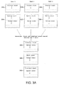
- a second, more commonly used, approach is to provide a system where certain exception stacks are shared between the task, an example of such a system being illustrated in figure 3A .
- a system is shown having 2 stacks per task, and an additional 3 stacks shared system wide between the three tasks.
- the system illustrated in figure 3A has the same five execution modes as the system illustrated in figure 2A , although it will be appreciated that other embodiments may have more or fewer execution modes.
- any data on the corresponding exception stack is transferred to either the user/process stack or the system stack of the relevant task, thereby ensuring that all of the shared exception stacks remain empty at all points where a context switch may be required.
- FIG 3B shows the task control blocks 360, 370 and 380 for tasks 1, 2 and 3 respectively.
- the letter in parenthesis next to each instruction shows the number of memory or data cycles required for each instruction, where M equals one memory cycle, and D equals one data cycle.
- the number of cycles are illustrated up to the point marked "***INTERRUPT RE-ENABLE***", which is the point where interrupts can be re-enabled.
- the number of cycles between the start of the interrupt handler and this point determines the interrupt latency, a high number of cycles leading to a high interrupt latency, whilst a low number of cycles leads to a low interrupt latency.
- Not shown in the code fragment above are a number of additional cycles required by the hardware to deliver control to the first instruction of the interrupt handler. This number of cycles is the same with or without the use of preferred embodiments of the present invention, and so is omitted here for clarity.
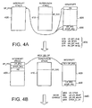
- the processor has entered an interrupt mode of operation, where it has access to registers 420.
- the return state data of the processor from this interrupt mode of operation is stored in the return state registers, identified in figure 4A as registers 430.
- the return state data comprises the registers LR_IRQ and SPSR_IRQ.
- Figure 4A also illustrates two of the stacks, namely the interrupt stack 400 accessible from the interrupt mode of operation, and the supervisor stack 410, the supervisor stack 410 not being accessible from the interrupt mode of operation, since in the interrupt mode of operation the processor is unable to access the register containing the supervisor stack pointer SP_SVC.
- the first process that needs to be performed is to save the return state, i.e. the contents of registers 430, onto the interrupt stack 400.
- the contents of register R ⁇ are also saved to be interrupt stack 400, so that register R ⁇ can be used as a temporary register.
- This operation is performed by the four instructions identified by the reference 435 in figure 4A and set out in the above code fragment.
- the initial SUB instruction set out in the above code fragment is merely required since in the disclosed implementation the link register LR_IRQ needs to be adjusted in order for it to correctly point to the return address.
- the next step is to store the stack pointer SP_IRQ of the interrupt stack into register R ⁇ , which is now being used as a temporary register. This will enable that stack pointer to be accessible once the interrupt mode of operation is exited.
- the processor mode is changed to the system mode, this being performed by the four instructions referenced by reference numeral 445 in figure 4B . Accordingly, as shown in figure 4C , the processor is now in the supervisor mode of operation, where it has access to the registers 450. Since register R ⁇ is shared between the modes of operation, register R ⁇ still contains the stack pointer for the interrupt stack 400. However, the return state is now the return state of the processor from the supervisor mode of operation, as stored in registers 440.
- the process now stores the content of one of the registers on the supervisor stack, so that it can be used as a temporary register.
- the contents of register R1 are stored onto the supervisor stack.
- the process then recovers the return state information and the saved R ⁇ value from the interrupt stack 400, and saves it onto the supervisor stack 410.
- These processes are performed by the seven instructions referenced by numeral 455 in figure 4C .
- the SUB instruction is used to decrement the supervisor stack pointer by eight 4 byte words.
- a STR instruction is used to store the contents of R1 into a particular location in the supervisor stack 410.
- An LDR and STR instruction is then used to store LR_IRQ into a particular location on the supervisor stack, with the following LDR and STR instruction being used to store SPSR_IRQ into a particular location on the supervisor stack.
- the temporary register R1 is used for this purpose.
- the final LDR instruction is used to store the value of R ⁇ stored on the interrupt stack 400 into the temporary register R1.
- the subsequent STR instruction required to then store that value onto the supervisor stack is not immediately performed, since at this point it is now safe to re-enable interrupts, and the re-enablement of interrupts is given priority in order to minimise the interrupt latency. It should be noted that at no previous point was it safe to re-enable interrupts since there was data stored on the interrupt stack 400 which could be overwritten if a second interrupt was allowed to be serviced before all of that data had been recovered from the interrupt stack 400.
- the first STR instruction stores the contents of R1 into a specified location in the supervisor stack, this register actually containing the original R ⁇ data, the contents of R1 having already been moved into the supervisor stack by one of the instructions executed in figure 4C .
- the contents of registers R2, R3, R12 and LR_SVC are then also moved to the supervisor stack. 410.
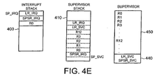
- Figure 4E then illustrates the final state of the supervisor stack 410 at this point. It should be noted that in figures 4D and 4E , the interrupt stack 400 is still shown as containing the three pieces of data originally moved to the interrupt stack in figure 4A . However, it will be clear that this data is now redundant since it is stored on the supervisor stack, and accordingly to all intents and purposes the interrupt stack 400 can be considered to be empty. Accordingly, at this point, it is now safe to continue and service the interrupt, this typically taking place via a context switch to another task.
- the interrupt handler takes eleven D type cycles and nine N type cycles before interrupts can be re-enabled, leading to a relatively high interrupt latency. Also significant is the number of instructions taken before interrupts can be re-enabled. As can be seen from the above enclosed code fragment in combination with figures 4A to 4E , twenty instructions need to be executed before interrupts can be re-enabled using this prior art approach.
- the letters in parenthesis show the number of cycles, the letters 2M next to the SRSDB instruction indicating two memory cycles.
- the code fragment starts with a SUB instruction identical to that included in the prior art code fragment discussed earlier, as mentioned earlier this instruction being required to ensure that the interrupt link register LR_IRQ points to the correct return address.
- a new instruction provided in accordance with preferred embodiments namely an SRS instruction, is performed to directly save the return state data onto the supervisor stack 510 whilst operating in the interrupt mode of operation.
- the format of this instruction will be discussed in detail later.
- the letters DB are appended to the SRS instruction to denote the address mode of the supervisor stack, in this example "Decrement Before”.
- the instruction also includes a field identifying the stack to which the return state data is to be saved, this field in this example containing the stack pointer SP_SVC for the supervisor stack 510.
- the exclamation mark at the end of the instruction indicates that the stack pointer should be updated once the return state data has been saved.
- the contents of the interrupt stack and supervisor stack are as illustrated in figure 5B .
- the contents of registers LR_IRQ and SPSR_IRQ have been added to the supervisor stack 510, and the supervisor stack pointer SP_SVC has been updated.
- the supervisor stack pointer SP_SVC has been updated.
- interrupt stack 500 is empty, a context switch is permissible without the need to context switch the interrupt stack, i.e. without the need to have a separate interrupt stack per task, and accordingly this process can be employed within a system such as that shown in figure 3A and 3B .
- Figure 5C shows the registers 550 accessible from the supervisor mode of operation, including the registers 560 containing the return state from the supervisor mode of operation.
- the process can continue to save the remainder of the process contest Since the registers involved can be stored in sequential locations of the supervisor stack, it is possible to perform this operation via a single STM instruction, this instruction being referenced by the reference numeral 570 in figure 5C , and the process being illustrated schematically by the various lines between the supervisor registers 550 and the supervisor stack 510.
- the letters DB appended to the STM instruction identify that the supervisor stack is operating in Decrement Before address mode, the exclamation mark after the stack pointer ID in the STM instruction indicating that the stack pointer should be adjusted.
- the registers to be stored are then identified in the instruction.
- Figure 5D illustrates the content of the supervisor stack 510 after the STM instruction has been performed. It will be noted that the contents of the supervisor stack 510 are the same as the contents of the supervisor stack 410 illustrated earlier with reference to figure 4E , albeit with a slightly different ordering of the data, and accordingly it can be seen that the process of preferred embodiments illustrated with reference to figures 5A to 5D produces the same result as the prior art process illustrated with reference to figures 4A to 4E . However, as is apparent from the code fragment enclosed earlier, the technique of the preferred embodiment, which incorporates the new SRS instruction, ensures that the interrupt handler only takes five D type cycles and two M type cycles before interrupts can be re-enabled.
- the interrupt handler using the approach of the preferred embodiment only needs to execute six instructions before re-enabling interrupts, as opposed to the twenty instructions that needed to be performed in accordance with the prior art approach.
- the interrupt handler takes fewer D type cycles, fewer M type cycles and fewer instructions. It should also be noted that M type cycles may be much slower than D type cycles on a slow memory system and also that for each instruction executed there may be an additional memory fetch performed to fetch the instruction itself.
- the SRS instruction saves the return state of the processor to a stack specified by ⁇ fully_qualified_stack_pointer> which specifies a stack belonging to one of the available modes on the processor. If the ⁇ fully_qualified_stack_pointer> is followed with the "
- the ⁇ fully_qualified_stack_pointer> may take any of the values SP_USER, SP_FIQ, SP_IRQ, SP_SVC, SP_ABT or SP_UND.
- ⁇ COND> specifies one of a number of conditions which must be true in order for the operation to execute.
- the CPSR register accessible by the processor contains four flags, referred to hereafter as N,Z,V,C.
- the flag N is set to one if the result of the last arithmetic operation was negative
- the flag Z is set to one if the result of the last arithmetic operation was zero
- the flag V is set to one if the result of the last arithmetic operation overflowed
- the flag C is set to one if the result of the last arithmetic operation resulted in a carry.
- a table is provided illustrating the various values that the ⁇ COND> field may take, along with a description of each value, and a determination as to what this equates to in terms of the N,Z,V and C flags available in the CPSR register.
- that table in effect describes how the processor will determine whether to execute the instruction based on the N,Z,V and C flags present in the CPSR register.
- the processor will check to see whether the flag N has been set to one and if so will execute the instruction, otherwise, the instruction will not execute. If the ⁇ COND> field is not specified, this is equivalent to specifying a ⁇ COND> symbol of "AL", indicating that the operation should always be executed.
- the ⁇ addr_mode> field specifies an addressing mode for the operation, the various addressing modes available in the preferred embodiment being set out above in association with the abbreviated Backus-Naur form of the instruction.
- the ⁇ fully_qualified_stack_pointer> field specifies the fully qualified name of a stack pointer belonging to one of the execution modes of the processor.
- SRS instructions that may be derived from the abbreviated Backus_Naur form: SRSDB SP_SVC! SRSEQDB SP_SVC! SRSEQDB SP_SVC
- FIG. 6 is a block diagram illustrating a system incorporating a data processing apparatus in accordance with preferred embodiments of the present invention.
- the data processing apparatus takes a form of a CPU core 60 provided within a CPU 10.
- the CPU core 60 will incorporate a processing unit for executing data processing instructions, and a set of registers 70 accessible by that processing unit.
- the CPU 10 will typically include the CPU core 60, and a number of other optional elements, such as a Memory Management Unit (MMU) 45 and a cache 50.
- MMU Memory Management Unit
- CPU 10 will typically be connected to other elements via a bus 30, and hence may be connected to a Read Only Memory (ROM) 40 and a Random Access Memory (RAM) 20.
- ROM Read Only Memory
- RAM Random Access Memory
- the ROM 40 may be arranged to store, amongst other things, instructions 80 to be executed by the CPU core 60.
- the stacks 90 provided for each mode of operation of the processing unit may be stored within the RAM 20.
- use of the preferred embodiment results in a number of advantages.
- use of the preferred embodiment of the present invention enables the code size to be reduced.
- the preferred embodiment may be used to reduce the number of instructions at the start of an interrupt handler from twenty to six. Additionally, use of the preferred embodiment will typically result in improved performance.
- the preferred embodiment reduces the number of cycles at the start of the interrupt handler from 127 to 37. The reduction in the number of cycles also enables the interrupt latency to be reduced, since these cycles typically occur at a critical point where interrupts are disabled.
- a further surprising advantage of employing the technique of the preferred embodiment is that it may be used to reduce power consumption of a processor, power consumption being extremely important in battery powered devices such a mobile telephones and Personal Digital Assistants (PDAs).
- PDAs Personal Digital Assistants
Landscapes
- Engineering & Computer Science (AREA)
- Software Systems (AREA)
- Theoretical Computer Science (AREA)
- Physics & Mathematics (AREA)
- General Engineering & Computer Science (AREA)
- General Physics & Mathematics (AREA)
- Executing Machine-Instructions (AREA)
- Advance Control (AREA)
Description
- The present invention relates to a data processing apparatus and method for saving return state, and more specifically to the saving of the return state in a data processing apparatus incorporating a processing unit having a plurality of modes of operation, with each mode of operation having a corresponding stack storing data associated with that mode.
- Within such a data processing apparatus, it is known to provide instructions which are arranged to save return state data on the stack associated with a current mode of operation. A typical example of where such instructions are used is upon occurrence of an exception, in which event the return state data is saved on the stack associated with the exception mode of operation. This procedure may be required for a variety of reasons. For example, such a data processing apparatus may typically support multi-tasking, and when a context switch is to be performed in order to enable another task to execute, the stack or stacks associated with the modes of operation of the current task need to be swapped in order to enable that new task to execute. In systems where the stacks are accessed using stack pointers, this swapping is usually performed by swapping the stack pointer or stack pointers of the various stacks. In such a data processing apparatus, it is typically required that the return state data is saved on a stack which will be swapped when the context switch occurs.
- In order to facilitate context switching, it is required that all stacks that are non-empty at the time of the context switch are swapped. On a processor with multiple stacks, this can require swapping every stack belonging to a particular task. Additionally, if this approach is used, a separate stack per mode of operation has to be maintained for each task, and this leads to increased memory consumption and increased time taken to swap each stack belonging to each task. For example, the current processor produced by ARM Limited has six separate stacks corresponding to six modes of operation, namely System/User, FIQ (Fast Interrupt Request), Supervisor, Abort, IRQ (Interrupt ReQuest) and Undefined, where FIQ and IRQ are two interrupt modes of operation. Therefore, using the above approach, a context switch may require the swapping of six separate stacks, and each task may have to reserve memory for six separate stacks. An example of such an approach will be discussed later with reference to
figures 2A and2B .Figures 2A and2B show a system with five rather than six stacks, since they illustrate an example of a typical system where it is assumed that the FIQ mode is reserved for a single high priority interrupt which will not cause a context switch. - An alternative, more commonly used, approach is to share the various exception stacks amongst the tasks, and to then transfer any data on an exception stack to either the user stack or a single per process privileged mode stack on entry to an exception. Taking the earlier example of the processor currently produced by ARM Limited, this would equate to transferring data from the FIQ, Abort, IRQ or Undefined stacks to the User or Supervisor stacks. This approach ensures that all exception stacks (FIQ, Abort, IRQ and Undefined in the example of the ARM processor) remain empty at all points where a context switch may be required.
- The data saved on entry to an exception is usually that data which is required for the task to continue execution from the point at which the exception occurred. This data is termed the "return state data".
- The above-described second approach requires that on entry to an exception, the return state is saved on the stack associated with the exception mode of operation, the processor user or privileged mode is entered, and the return state data is then read back from the stack associated with the exception mode of operation and saved on the stack associated with the user or privileged mode. The return state cannot simply be saved from the user or privileged mode after the user or privileged mode has been entered, because the return state is not accessible from that mode. This process will be discussed in more detail later with reference to the example of
figures 3A and3B . - This process of saving the return state data on the stack belonging to the exception mode of operation, changing mode, recovering the return state data from the stack belonging to the exception mode of operation, and saving the return state data on the user or privileged mode stack, requires a significant number of instructions wich adversely affects code size and performance of the data processing apparatus.
- Additionally, it should be noted that this processing is required at a critical point in interrupt handling when interrupts are disabled, therefore leading to significant interrupt latency. It should be noted that interrupts cannot be re-enable until the return state data is saved on the user or privileged mode stack in case a further interrupt arrives and overwrites the return state data before it an be saved.
- BOB SMTIH:"Re: Using the int instruction in prot mode at ] relates to protection mechanisms. A CPU having four privileged levels, PL0 to PL3 and three stacks for PL0,PL1 and PL3 are disclosed. During a ring transition from PL3 to PL0, the CPU switches stacks since a return frame is written on the PL0 stack.
- Accordingly, it is desirable to provide a more technique for saving the return state data upon occurence of an exception.
- Viewed from a first aspect, the present invention provides a data processing apparatus, comprising: a processing unit for executing data processing instructions, the processing unit having a plurality of modes of operation, each mode of operation having a different corresponding stack for storing data associated with that mode; the processing unit being responsive to a return state data processing instruction to write return state data of the processing unit from its current mode of operation to a stack corresponding to a mode of operation different from the current mode of operation whilst remaining in the current mode of operation.
- In accordance with the present invention, a return state data processing instruction is provided which is used to cause the processing unit to write the return state data of the processing unit from its current mode of operation to a stack corresponding to a different mode of operation to the current mode of operation.
- It has been found that the present invention enables code sizes to be reduced and performance to be improved. The invention may be used in a variety of implementations, but is of particular benefit in real time operating systems, particularly those requiring fast context switching, for example multi-tasking operating systems such as Linux.
- In preferred embodiments, the return state data processing instruction is involved upon occurence of an exception.
- It will be appreciated that the exception may be any suitable exception, and for example can be any of the standard exceptions occuring within a data processing apparatus, including interrupts of all types, aborts of all types, undefined instruction exceptions, address exceptions, software interrupts and any other exceptions that may be generated. More particularly, in preferred embodiments, the exception is one or more of Data Abort, Prefetch Abort, Address Exception, Undefined Instruction, Reset, Software Interrupt, Interrupt Request or Fast Interrupt Request.
- Hence, in preferred embodiments, the exception causing the data processing instruction to be invoked may be any of a predetermined set of exceptions, and that predetermined set of instructions may include one or more interrupts.
- It has been found that the preferred embodiment of the present invention enables code size to be reduced, by reducing the number of instructions required at the start of an exception handler. Furthermore, the preferred embodiment enables the performance to be improved, by reducing the number of cycles required at the start of the exception handler. As these cycles typically occur at a critical point where interrupts are disabled, this has the advantage of significantly reducing interrupt latency. The preferred embodiment of the invention may be used in a variety of implementations, but is of particular benefit in real time operating systems, particularly those requiring very low interrupt latency, for example operating systems controlling disk drives.
- In preferred embodiments, the data processing apparatus further comprises: a set of registers, including a plurality of return state registers for storing the return state data of the processing unit for each mode of operation, the processing unit being able only to access return state registers containing the return state data of the processing unit from its current mode of operation. This requires the return state to be saved to an appropriate stack prior to changing the mode of operation, since once the mode of operation has been changed, those return state registers will not be accessible except by re-entering the original exception mode.
- It will be appreciated that the stacks may be implemented in a variety of ways. However, in preferred embodiments, each stack has a stack pointer associated therewith identifying a location within the stack, the stack pointer for a particular stack only being accessible from the corresponding mode of operation. Accordingly, in any particular mode of operation, the processing unit will typically only be able to access its corresponding stack, since it will typically only have access to that stack's stack pointer.
- In preferred embodiments where a set of registers is provided within the data processing apparatus, the set of registers preferably further include a plurality of stack pointer registers for storing the stack pointers for each stack, the processing unit being able only to access the stack point register containing the stack pointer for the stack corresponding to its current mode of operation. Hence, the processing unit in its current mode of operation can only access the stack point register in order to obtain the stack pointer for its corresponding stack.
- It will be appreciated that the return state data processing instruction provided in accordance with the present invention may take a variety of forms. However, in preferred embodiments the return state data processing instruction includes a stack identifier field for identifying the stack to which the return state data of the processing unit is to be written.
- In preferred embodiments, where each stack has a stack pointer associated therewith, it is apparent that the processing unit needs to have knowledge of the stack pointer in order to write the return state data to the appropriate location(s) within the destination stack. Accordingly, in preferred embodiments, the stack identifier field is arranged to specify a stack pointer for the stack to which the return state data of the processing unit is to be written, thereby enabling the processing unit to access an appropriate location in that stack when writing the return state data to that stack.
- Further, in preferred embodiments, the return state data processing instruction includes an optional update field, which is set to indicate that the stack pointer is to be updated once the return state data has been written to the stack. Typically the stack pointer will be updated, but there may be circumstances where it is not appropriate to update the stack pointer, and accordingly this optional update field provides the flexibility for either leaving the stack pointer at its current value, or updating it to take account of the return state data written to the stack.
- In preferred embodiments, different types of stack may be provided, which use different address modes for determining how the stack pointer is updated. Examples of four different stack types are:
- Full Ascending - The stack grows upwards in memory and the stack pointer points to the last word pushed onto the stack;
- Empty Ascending - The stack grows upwards in memory and the stack pointer points one word above the last word pushed onto the stack;
- Full Descending - The stack grows downwards in memory and the stack pointer points to the last word pushed onto the stack; and
- Empty Descending - The stack grows downwards in memory and the stack pointer points one word below the last word pushed onto the stack.
- Hence, in preferred embodiments the return state data processing instruction includes an address mode field for identifying the address mode of the stack to which the return state data is to be written, this field being used by the processing unit to determine the address mode relevant to the destination stack.
- Depending on the exception occurring and other system state, it may be necessary to always invoke the return state data processing instruction, or instead to only invoke the return state data processing instruction if a particular condition exists. Accordingly, in preferred embodiments, the return state data processing instruction includes a condition field for specifying a condition for execution of the return state data processing instruction, such that the return state data processing instruction is only executed by the processing unit if the condition is met.
- In preferred embodiments, when an exception occurs, the processing unit will be placed into a corresponding exception mode of operation, and hence as an example, if an interrupt occurs, the processing unit will be placed into an interrupt mode of operation, if an abort occurs, the processing unit will be placed into an abort mode of operation, etc. Accordingly, the current mode of operation at the time the return state data processing instruction is executed is an exception mode of operation. In a preferred embodiment, the different mode of operation whose stack is used to store the return state data is a privileged mode of operation, for example a system wide privileged mode of operation. In an alternative embodiment, the different mode of operation may be the mode of operation of the processing unit prior to entry into the exception mode.
- It will be appreciated that the return state data may take a variety of forms. However, in preferred embodiments, the return state data comprises a saved program counter and a saved processor status, these being the program counter and processor status of the mode of operation which was exited to enter the current, i.e. exception, mode of operation.
- Viewed from a second aspect, the present invention provides a method of operating a data processing apparatus comprising a processing unit for executing data processing instructions, the processing unlit having a plurality of modes of operation, each mode of operation having a different corresponding stack for storing data associated with that mode, the method comprising the step of causing the processing unit to respond to a return state data processing instruction by writing return state data of the processing unit from its current mode of operation to a stack corresponding to a mode of operation different from current mode of operation whilst remaining in the current mode of operation.
- Viewed from a third aspect, the present invention provides a computer program operable to configure a data processing apparatus to perform a method in accordance with the second aspect of the present invention. The invention also relates to a carrier medium comprising such a computer program. The carrier medium may be any suitable device, for example a CDROM, a diskette, etc, or indeed may be a transmission medium such as an optical fibre, radio signal, etc.
- The present invention will be described further, by way of example only, with reference to a preferred embodiment thereof as illustrates in the accompanying drawings, in which:
-
Figure 1A is a diagram illustrating an example system configuration containing multiple stacks, each stack being associated with one or more modes of operation; -
Figure 1B illustrates the registers associated with each mode of operation in the system configuration offigure 1A ; -
Figure 2A shows an example known system configuration having three tasks, with each task having five separate stacks; -
Figure 2B shows a portion of the task control blocks associated with the system shown infigure 2A ; -
Figure 3A shows an example known system configuration having three tasks, each task having two separate stacks but with three exception stacks beings shared between the three tasks; -
Figure 3B shows a portion of the task control blocks associated with the system shown infigure 3A ; -
Figures 4A to 4E illustrate a sequence of instructions invoked upon occurrence of an exception in accordance with a prior art approach: -
Figures 5A to 5D illustrate a sequence of instructions performed upon occurrence of an exception in accordance with preferred embodiments of the present invention; and -
Figure 6 is a block diagram illustrating an example structure of a system incorporating a data processing apparatus in accordance with preferred embodiments of the present invention. -
Figures 1A and1B are block diagrams illustrating an example system having six modes of operation and a corresponding six stacks. However, the FIQ mode is reserved for high priority interrupts which do not cause context switching, and accordingly only five modes of operation and their corresponding five stacks are shown in the figures and discussed in the following description. Hence, with reference toFigure 1A , fivestacks figure 1B , which illustrates the registers accessible in each of the five modes of operation, namely a user mode, a privileged mode, an interrupt mode, an abort mode, and an undefined mode. As is clear fromfigure 1B , certain registers are accessible from any of the modes. However, the stack pointers for the five modes are named in this example as SP, SP_SVC, SP_IRQ, SP_ABT and SP_UND, and it is clear that in any particular mode of operation, the processor can only access the register containing the stack pointer for the stack associated with that mode of operation. Accordingly, the processor can only access the stack belonging to that mode of operation. - The privileged mode, and each of the exception modes (interrupt, abort and undefined) have associated return state data which is accessible only from the mode of operation associated with that return state. With reference to
figure 1B , the return state is named as LR_SYC, LR_IRQ, LR_ABT, LR_UND and also SPSR_SVC, SPSR_IRQ, SPSR_ABT and SPSR_UND, LR standing for "Link Register", and SPSR standing for "Saved Processor Status Register". The user mode also has a link register, but this is not used for storing return state information as there is no return state for the user mode since this is not an exception mode. That is to say, there is no exception which will cause entry to user mode, and therefore there is no need for user mode to store any return state data. -
Figure 2A illustrates, in block diagram form, a first prior art system configuration, in this example the system having three tasks, each task having five stacks corresponding to the five modes of operation. Accordingly,task 1 has aprocess stack 200, asystem stack 210, an interruptstack 220, anabort stack 230 and anundefined stack 240,task 2 has aprocess stack 202, a system stack 212, an interruptstack 222, anabort stack 232 and an undefined stack 242, andtask 3 has a process stack 204, a system stack 214, an interrupt stack 224, an abort stack 234 and an undefined stack 244. - Return state data is saved on the stack corresponding to the exception. For example, on occurrence of an interrupt, a task will enter the interrupt mode of operation, and the return state information will be saved on the interrupt stack. As will be appreciated from
figure 2A , this imposes additional overhead in terms of memory consumption by having to maintain five stacks per task. -
Figure 2B shows part of the task control block for each task, a task control block being an area of memory where a task saves all the information necessary for context switching. As part of this information, the stack pointers for each of the five stacks need to be stored, and hence thecontrol block 250 fortask 1 will have to store five stack pointers, the control block 260 fortask 2 will have to store five stack pointers, and the control block 270 fortask 3 will have to store five stack pointers. Accordingly, it will be appreciated that having five stacks per task imposes additional overhead both in terms of memory consumption by virtue of the additional memory needed in each task control block, and performance by virtue of the additional time taken to save and restore the additional registers in the task control block. - With the aim of improving upon this known technique, a second, more commonly used, approach is to provide a system where certain exception stacks are shared between the task, an example of such a system being illustrated in
figure 3A . In accordance with the example offigure 3A , a system is shown having 2 stacks per task, and an additional 3 stacks shared system wide between the three tasks. For the purposes of illustration, it is assumed that the system illustrated infigure 3A has the same five execution modes as the system illustrated infigure 2A , although it will be appreciated that other embodiments may have more or fewer execution modes. - On occurrence of an exception, any data on the corresponding exception stack is transferred to either the user/process stack or the system stack of the relevant task, thereby ensuring that all of the shared exception stacks remain empty at all points where a context switch may be required. As a result of this, it is only necessary to store the stack pointers for the user/process and system modes in the corresponding task control block, this being illustrated by
figure 3B which shows the task control blocks 360, 370 and 380 fortasks - As will be apparent from
figures 3A and3B , significant advantages are obtained through use of this approach in terms of memory consumption and performance. The system illustrated infigures 3A and3B requires Nt x 2 + 3 stacks, whereas the system illustrated infigures 2A and2B requires Nt x 5 stacks, where Nt is the number of tasks in the system. Further, the system illustrated infigures 2A and2B requires Nt x 5 words of context block information, whereas the system illustrated infigures 3A and3B requires Nt x 2 words of context block information. In performance terms, a context switch between tasks on a system as illustrated infigures 2A and2B requires five word loads and stores, whereas a context switch between tasks on the system as illustrated infigures 3A and3B requires two word loads and stores. - To provide an example of the code necessary at the start of an interrupt to implement the system illustrated in
figures 3A and3B using a known technique, set out below is a code fragment written in ARM assembler:

- The letter in parenthesis next to each instruction shows the number of memory or data cycles required for each instruction, where M equals one memory cycle, and D equals one data cycle. The number of cycles are illustrated up to the point marked "***INTERRUPT RE-ENABLE***", which is the point where interrupts can be re-enabled. The number of cycles between the start of the interrupt handler and this point determines the interrupt latency, a high number of cycles leading to a high interrupt latency, whilst a low number of cycles leads to a low interrupt latency. Not shown in the code fragment above are a number of additional cycles required by the hardware to deliver control to the first instruction of the interrupt handler. This number of cycles is the same with or without the use of preferred embodiments of the present invention, and so is omitted here for clarity.
- To help illustrate the process being performed by the various instructions illustrated in the above code fragment,
figures 4A to 4E are enclosed, and these figures will now be discussed. - In this example, it is assumed that an interrupt exception has occurred and accordingly the processor has entered an interrupt mode of operation, where it has access to
registers 420. The return state data of the processor from this interrupt mode of operation is stored in the return state registers, identified infigure 4A as registers 430. In particular, the return state data comprises the registers LR_IRQ and SPSR_IRQ. -
Figure 4A also illustrates two of the stacks, namely the interruptstack 400 accessible from the interrupt mode of operation, and thesupervisor stack 410, thesupervisor stack 410 not being accessible from the interrupt mode of operation, since in the interrupt mode of operation the processor is unable to access the register containing the supervisor stack pointer SP_SVC. - The first process that needs to be performed is to save the return state, i.e. the contents of
registers 430, onto the interruptstack 400. In addition to saving the return state, the contents of register R∅ are also saved to be interruptstack 400, so that register R∅ can be used as a temporary register. This operation is performed by the four instructions identified by thereference 435 infigure 4A and set out in the above code fragment. The initial SUB instruction set out in the above code fragment is merely required since in the disclosed implementation the link register LR_IRQ needs to be adjusted in order for it to correctly point to the return address. - Accordingly, with reference to
figure 4B , we are now at a point where the contents of LR_IRQ, SPSR_IRQ and RØ are stored on the interruptstack 400. The stack pointer SP_IRQ of the interruptstack 400 is not decremented, because the return state and RØ data just saved on the interrupt stack will be loaded off the interrupt stack as soon as the process changes mode. It is safe to not decrement the stack pointer because it is not possible for any further interrupts to be serviced between saving the data and reading it after changing modes, because at this time interrupts are disabled. - As illustrated in
figure 4B , the next step is to store the stack pointer SP_IRQ of the interrupt stack into register RØ, which is now being used as a temporary register. This will enable that stack pointer to be accessible once the interrupt mode of operation is exited. - At this point, the processor mode is changed to the system mode, this being performed by the four instructions referenced by
reference numeral 445 infigure 4B . Accordingly, as shown infigure 4C , the processor is now in the supervisor mode of operation, where it has access to theregisters 450. Since register R∅ is shared between the modes of operation, register R∅ still contains the stack pointer for the interruptstack 400. However, the return state is now the return state of the processor from the supervisor mode of operation, as stored inregisters 440. - The process now stores the content of one of the registers on the supervisor stack, so that it can be used as a temporary register. In this example, the contents of register R1 are stored onto the supervisor stack. The process then recovers the return state information and the saved R∅ value from the interrupt
stack 400, and saves it onto thesupervisor stack 410. These processes are performed by the seven instructions referenced by numeral 455 infigure 4C . In particular, the SUB instruction is used to decrement the supervisor stack pointer by eight 4 byte words. Then, a STR instruction is used to store the contents of R1 into a particular location in thesupervisor stack 410. An LDR and STR instruction is then used to store LR_IRQ into a particular location on the supervisor stack, with the following LDR and STR instruction being used to store SPSR_IRQ into a particular location on the supervisor stack. It can be seen that the temporary register R1 is used for this purpose. The final LDR instruction is used to store the value of R∅ stored on the interruptstack 400 into the temporary register R1. However, the subsequent STR instruction required to then store that value onto the supervisor stack is not immediately performed, since at this point it is now safe to re-enable interrupts, and the re-enablement of interrupts is given priority in order to minimise the interrupt latency. It should be noted that at no previous point was it safe to re-enable interrupts since there was data stored on the interruptstack 400 which could be overwritten if a second interrupt was allowed to be serviced before all of that data had been recovered from the interruptstack 400. - Accordingly, transitioning now to
figure 4D , the enablement of interrupts is performed by the three instructions referenced by the numeral 465 infigure 4D , and included in the earlier code fragment In effect, these instructions read the CPSR register, clear the interrupt disable bit, and then write back the relevant data to the CPSR register, thereby re-enabling interrupts. - At this point, we can now continue saving the remainder of the process context, this being performed by the five STR instructions referenced by the numeral 475 in
figure 4D . In particular, it should be noted that the first STR instruction stores the contents of R1 into a specified location in the supervisor stack, this register actually containing the original R∅ data, the contents of R1 having already been moved into the supervisor stack by one of the instructions executed infigure 4C . The contents of registers R2, R3, R12 and LR_SVC are then also moved to the supervisor stack. 410. It should be noted that the contents of the other registers will automatically be saved by any code subsequently called which obeys the ATPCS (ARM Thumb Procedure Calling Standard), and accordingly do not need to be explicitly saved to the supervisor stack at this point (unless the code does not obey the ATPCS). -
Figure 4E then illustrates the final state of thesupervisor stack 410 at this point. It should be noted that infigures 4D and4E , the interruptstack 400 is still shown as containing the three pieces of data originally moved to the interrupt stack infigure 4A . However, it will be clear that this data is now redundant since it is stored on the supervisor stack, and accordingly to all intents and purposes the interruptstack 400 can be considered to be empty. Accordingly, at this point, it is now safe to continue and service the interrupt, this typically taking place via a context switch to another task. - As can be seen, using this known prior art technique, the interrupt handler takes eleven D type cycles and nine N type cycles before interrupts can be re-enabled, leading to a relatively high interrupt latency. Also significant is the number of instructions taken before interrupts can be re-enabled. As can be seen from the above enclosed code fragment in combination with
figures 4A to 4E , twenty instructions need to be executed before interrupts can be re-enabled using this prior art approach. - Having now described the process necessary at the start of an interrupt to implement a system such as that show in
figures 3A and3B in accordance with known prior art techniques, a discussion will now follow of the process necessary at the start of an interrupt to implement such a system in accordance with preferred embodiments of the present invention. In particular, to assist in the discussion, there is set out below a code fragment illustrating the code necessary at the start of an interrupt to implement a system such as that shown infigure 3A and3B in accordance with a preferred embodiment of the present invention:
 ; Save the return state directly onto the SVC stack using the SRS
 ; instruction.
 (D)      SUB      lr, lr, #4      ; Adjust LR_IRQ to point to return
                                      address
 (2M)      SRSDB   sp_svc!         ; Save return status on SVC stack

 ; Now change processor to system (SVC) mode, re-enabling interrupts
 ; at the same time. It is safe to re-enable interrupts at this time
 ; because the return state has been saved on the SVC stack. Therefore
 ; the interrupt stack is empty and a context switch is permissible
 ; without the need to context switch the interrupt stack (i.e.
 ; without the need to have a separate interrupt stack per task).
 (D)      MRS       lr, cpsr           ; Read cpsr
 (D)      BIC       lr, lr, #0x1f+0x80 ; Mask out mode bits and
                                         clear interrupt
 (D)      ORR       lr, lr, #0x13      ; Or in mode bits for SVC
                                         mode
 (D)     MSR        cpsr_c, lr         ; Write back new mode and
                                         interrupt bits

 ; *** INTERRUPT RE-ENABLE ***
 ; Cycle count before RE-ENABLING interrupts = 5 * D + 2 * M
 ;
 ; Interrupts are now re-enabled. Continue to save the remainder of
 ; the process context.
       STMDB sp!, {r0-r3, r12, 1r}

         ...                     ; Now continue and service the interrupt
- Without the technique of the preferred embodiment:

- With the technique of the preferred embodiment:

       SRS{<COND>}<addr_mode> <fully_qualified_stack_pointer>{!}
       <COND> ::=
               EQ |NE | CS | CC | MI | PL | VS | VC | HI | LS |GE |
               LT | GT | LE | AL | HS | LO
       <addr_mode> ::=
               IA | IB | DA | DB | FD | ED | FA | EA
       <fully_qualified_stack_pointer> ::=
              SP_USER | SP_FIQ | SP_IRQ | SP-SVC |SP_ABT | SP_UND
       <COND>        Description             Condition

       EQ            EQuals                  Z
       NE            Not Equal               !Z
       CS            Carry Set               C
       HS            unsigned Higher or Same C
       CC            Carry Clear             !C
       LO            unsigned Lower          !C
       MI            MInus                   N
       PL            Plus                    !N
       VS            overflow set            V
       VC            overflow clear          !V
       HI            unsigned HIgher         C & !Z
       LS            unsigned Lower or Same  !C |Z
       GE            Greater or Equal        !(N ^ V)
       LT            Less Than               N ^ V
       GT            Greater Than            !Z & !(N ^ V)
       LE            Less than or Equal      Z | (N ^ V)
       AL            ALways                  1

       <addr_mode>   Description
       IA            Increment After (equivalent to EA)
       EA            Empty Ascending (equivalent to IA)
       IB            Increment Before (equivalent to FA)
       FA            Full Ascending (equivalent to IB)
       DB            Decrement Before (equivalent to FD)
       FD            Full Descending (equivalent to DB) DA Decrement After (equivalent to ED)
       ED            Empty Descending (equivalent to DA)

       <fully_qualified_stack_pointer>       Description
       SP_USER                       The User mode stack pointer
       SP_FIQ                        The Fast Interrupt Request stack pointer
       SP_IRQ                        The Interrupt ReQuest stack pointer
       SP_SVC                        The Supervisor stack pointer
       SP_ABT                        The Abort stack pointer
       SP_UND                        The Undefined stack pointer
| SRSDB | SP_SVC! |
| SRSEQDB | SP_SVC! |
| SRSEQDB | SP_SVC |
- Without the technique of preferred embodiments:


- With the technique of preferred embodiments:


Claims (18)
- A data processing apparatus, comprising:a processing unit (10) for executing data processing instructions, the processing unit having a plurality of modes of operation characterized in that each mode of operation has a different corresponding stack (100, 110,120, 130, 140, 500, 510) for storing data associated with that mode; and in thatthe processing unit is responsive to a return state data processing instruction to write return state data of the processing unit from its current mode of operation to a stack (510) corresponding to a mode of operation different from the current mode of operation whilst remaining in the current mode of operation.
- A data processing apparatus as claimed in Claim 1, wherein the return state data processing instruction is invoked upon occurrence of an exception.
- A data processing apparatus as claimed in Claim 2, wherein the exception is any of a predetermined set of exceptions.
- A data processing apparatus as claimed in Claim 3, wherein the predetermined set of exceptions includes one or more interrupts.
- A data processing apparatus as claimed in any preceding claim, further comprising:a set of registers, including a plurality of return state registers for storing the return state data of the processing unit for each mode of operation, the processing unit being able only to access return state registers containing the return state data of the processing unit from its current mode of operation.
- A data processing apparatus as claimed in any preceding claim, wherein each stack has a stack pointer (SP_IRQ, SP_SVC) associated therewith identifying a location within the stack, the stack pointer for a particular stack only being accessible from the corresponding mode of operation.
- A data processing apparatus as claimed in Claim 6 when dependent on Claim 5, wherein the set of registers include a plurality of stack pointer registers for storing the stack pointers for each stack, the processing unit being able only to access the stack point register containing the stack pointer for the stack corresponding to its current mode of operation.
- A data processing apparatus as claimed in any preceding claim, wherein the return state data processing instruction includes a stack identifier field for identifying the stack to which the return state data of the processing unit is to be written.
- A data processing apparatus as claimed in Claim 8, wherein the stack identifier field is arranged to specify a stack pointer for the stack to which the return state data of the processing unit is to be written, thereby enabling the processing unit to access an appropriate location in that stack when writing the return state data to that stack.
- A data processing apparatus as claimed in Claim 9, wherein the return state data processing instruction includes an optional update field, which is set to indicate that the stack pointer is to be updated once the return state data has been written to the stack.
- A data processing apparatus as claimed in any of claims 8 to 10, wherein the return state data processing instruction includes an address mode field for identifying the address mode of the stack to which the return state data is to be written.
- A data processing apparatus as claimed in any of claims 8 to 11, wherein the return state data processing instruction includes a condition field for specifying a condition for execution of the return state data processing instruction, such that the return state data processing instruction is only executed by the processing unit if the condition is met.
- A data processing apparatus as claimed in any preceding claim, wherein the current mode of operation is an exception mode, and the different mode of operation is privileged mode of operation.
- A data processing apparatus as claimed in any preceding claim, wherein the current mode of operation is an exception mode, and the different mode of operation is the mode of operation of the processing unit prior to entry into the exception mode.
- A data processing apparatus as claimed in any preceding claim, wherein the return state data comprises a saved program counter and a saved processor status.
- A method of operating a data processing apparatus comprising a processing unit (10) for executing data processing instructions, the processing unit having a plurality of modes of operation, each mode of operation having a different correspondind stack (100, 110, 120, 130, 140, 500, 510) for storing data associated with that mode, the method comprising the step of:causing the processing unit to respond to a return state data processing instruction by writing return state data of the processing unit from its current mode of operation to a stack (510) corresponding to a mode of operation different from the current mode of operation whilst remaining in the current mode of operation.
- A computer program operable to configure a data processing apparatus to perform a method as claimed in Claim 16.
- A carrier medium comprising a computer program as claimed in Claim 17.
Applications Claiming Priority (3)
| Application Number | Priority Date | Filing Date | Title |
|---|---|---|---|
| GB0028869A GB2369464B (en) | 2000-11-27 | 2000-11-27 | A data processing apparatus and method for saving return state |
| GB0028869 | 2000-11-27 | ||
| PCT/GB2001/004252 WO2002042914A1 (en) | 2000-11-27 | 2001-09-24 | A data processing apparatus and method for saving return state |
Publications (2)
| Publication Number | Publication Date |
|---|---|
| EP1337918A1 EP1337918A1 (en) | 2003-08-27 |
| EP1337918B1 true EP1337918B1 (en) | 2009-08-12 |
Family
ID=9903938
Family Applications (1)
| Application Number | Title | Priority Date | Filing Date |
|---|---|---|---|
| EP01967554A Expired - Lifetime EP1337918B1 (en) | 2000-11-27 | 2001-09-24 | A data processing apparatus and method for saving return state |
Country Status (13)
| Country | Link |
|---|---|
| US (1) | US6904517B2 (en) |
| EP (1) | EP1337918B1 (en) |
| JP (2) | JP5295475B2 (en) |
| KR (1) | KR100848603B1 (en) |
| CN (1) | CN1227589C (en) |
| AU (1) | AU2001287927A1 (en) |
| DE (1) | DE60139567D1 (en) |
| GB (1) | GB2369464B (en) |
| IL (2) | IL155407A0 (en) |
| MY (1) | MY127357A (en) |
| RU (1) | RU2275679C2 (en) |
| TW (1) | TW556093B (en) |
| WO (1) | WO2002042914A1 (en) |
Families Citing this family (31)
| Publication number | Priority date | Publication date | Assignee | Title |
|---|---|---|---|---|
| DE69734399D1 (en) * | 1996-01-24 | 2006-03-02 | Sun Microsystems Inc | METHOD AND DEVICE FOR STACKING CACHE STORAGE |
| US6880030B2 (en) * | 2000-12-13 | 2005-04-12 | Wind River Systems, Inc. | Unified exception handling for hierarchical multi-interrupt architectures |
| US7313797B2 (en) * | 2002-09-18 | 2007-12-25 | Wind River Systems, Inc. | Uniprocessor operating system design facilitating fast context switching |
| US7496896B2 (en) * | 2003-07-17 | 2009-02-24 | Computer Associates Think, Inc. | Accessing return values and exceptions |
| JP2008522277A (en) * | 2004-11-30 | 2008-06-26 | コーニンクレッカ フィリップス エレクトロニクス エヌ ヴィ | Efficient switching between prioritized tasks |
| US7853960B1 (en) | 2005-02-25 | 2010-12-14 | Vmware, Inc. | Efficient virtualization of input/output completions for a virtual device |
| US7877629B2 (en) * | 2005-06-01 | 2011-01-25 | Sanmina-Sci | Facilitating handling of exceptions in a program implementing a M-on-N threading model |
| TW200719141A (en) * | 2005-11-07 | 2007-05-16 | Cheertek Inc | Flash memory access method and circuit of an embedded system |
| JP4961781B2 (en) * | 2006-03-14 | 2012-06-27 | ソニー株式会社 | Information processing apparatus, its activation method, and program |
| US7797681B2 (en) * | 2006-05-11 | 2010-09-14 | Arm Limited | Stack memory selection upon exception in a data processing system |
| RU2340933C2 (en) * | 2006-10-19 | 2008-12-10 | Общество с ограниченной ответственностью "Юникор микросистемы" | Method of computation process context switching during program interrupt or subroutine jump |
| EP2150889A1 (en) * | 2007-04-10 | 2010-02-10 | Cambridge Consultants Limited | Data processing apparatus |
| US7979685B1 (en) * | 2007-11-27 | 2011-07-12 | Oracle America, Inc. | Multiple instruction execution mode resource-constrained device |
| WO2010004242A2 (en) * | 2008-07-10 | 2010-01-14 | Cambridge Consultants Limited | Data processing apparatus, for example using vector pointers |
| US7853827B2 (en) * | 2008-08-29 | 2010-12-14 | International Business Machines Corporation | Isotropic processor |
| GB2478733B (en) * | 2010-03-15 | 2013-08-14 | Advanced Risc Mach Ltd | Apparatus and method for handling exception events |
| US20120054773A1 (en) * | 2010-08-31 | 2012-03-01 | International Business Machines Corporation | Processor support for secure device driver architecture |
| US9405637B2 (en) | 2011-01-18 | 2016-08-02 | Texas Instruments Incorporated | Locking/unlocking CPUs to operate in safety mode or performance mode without rebooting |
| US9477834B2 (en) | 2012-02-08 | 2016-10-25 | Arm Limited | Maintaining secure data isolated from non-secure access when switching between domains |
| US9202071B2 (en) | 2012-02-08 | 2015-12-01 | Arm Limited | Exception handling in a data processing apparatus having a secure domain and a less secure domain |
| GB2499287A (en) * | 2012-02-08 | 2013-08-14 | Advanced Risc Mach Ltd | Exception handling in data processing with different security domains |
| US9116711B2 (en) | 2012-02-08 | 2015-08-25 | Arm Limited | Exception handling in a data processing apparatus having a secure domain and a less secure domain |
| US9213828B2 (en) | 2012-02-08 | 2015-12-15 | Arm Limited | Data processing apparatus and method for protecting secure data and program code from non-secure access when switching between secure and less secure domains |
| US10210349B2 (en) | 2012-02-08 | 2019-02-19 | Arm Limited | Data processing apparatus and method using secure domain and less secure domain |
| US9672164B2 (en) | 2012-05-31 | 2017-06-06 | Nxp Usa, Inc. | Methods and systems for transitioning between a user state and a supervisor state based on a next instruction fetch address |
| CN103268145B (en) * | 2013-03-06 | 2016-08-17 | 上海云间半导体科技有限公司 | For the method preserving the virtual address of access instruction |
| GB2538091B (en) * | 2015-05-07 | 2018-03-14 | Advanced Risc Mach Ltd | Verifying correct code execution context |
| GB2543306B (en) * | 2015-10-14 | 2019-05-01 | Advanced Risc Mach Ltd | Exception handling |
| CN109409083B (en) * | 2018-09-21 | 2021-04-13 | 中国科学院信息工程研究所 | Device for detecting return address tampering in stack |
| CN109409086B (en) * | 2018-09-21 | 2021-04-13 | 中国科学院信息工程研究所 | Device for detecting falsified return address in stack based on newly added instruction |
| CN115080122A (en) * | 2022-07-22 | 2022-09-20 | 飞腾信息技术有限公司 | Processor, device, method and chip for saving and restoring context data |
Family Cites Families (52)
| Publication number | Priority date | Publication date | Assignee | Title |
|---|---|---|---|---|
| US3889243A (en) | 1973-10-18 | 1975-06-10 | Ibm | Stack mechanism for a data processor |
| US4236204A (en) | 1978-03-13 | 1980-11-25 | Motorola, Inc. | Instruction set modifier register |
| US4587632A (en) | 1980-05-27 | 1986-05-06 | At&T Bell Laboratories | Lookahead stack oriented computer |
| US4922414A (en) | 1982-12-17 | 1990-05-01 | Symbolics Inc. | Symbolic language data processing system |
| US4926322A (en) * | 1987-08-03 | 1990-05-15 | Compag Computer Corporation | Software emulation of bank-switched memory using a virtual DOS monitor and paged memory management |
| DE3726192A1 (en) | 1987-08-06 | 1989-02-16 | Otto Mueller | STACK CONTROL |
| JPH01258040A (en) * | 1988-04-07 | 1989-10-16 | Fujitsu Ltd | Saving restoring processing system for stack information |
| US5136696A (en) | 1988-06-27 | 1992-08-04 | Prime Computer, Inc. | High-performance pipelined central processor for predicting the occurrence of executing single-cycle instructions and multicycle instructions |
| US5440749A (en) | 1989-08-03 | 1995-08-08 | Nanotronics Corporation | High performance, low cost microprocessor architecture |
| JP3212656B2 (en) * | 1991-02-08 | 2001-09-25 | 株式会社日立製作所 | Data processing system and microcomputer |
| US5303378A (en) * | 1991-05-21 | 1994-04-12 | Compaq Computer Corporation | Reentrant protected mode kernel using virtual 8086 mode interrupt service routines |
| JP2585905B2 (en) * | 1991-10-18 | 1997-02-26 | 松下電器産業株式会社 | Multitask execution device |
| US5640548A (en) * | 1992-10-19 | 1997-06-17 | Motorola, Inc. | Method and apparatus for unstacking registers in a data processing system |
| US5455775A (en) | 1993-01-25 | 1995-10-03 | International Business Machines Corporation | Computer design system for mapping a logical hierarchy into a physical hierarchy |
| GB2289353B (en) * | 1994-05-03 | 1997-08-27 | Advanced Risc Mach Ltd | Data processing with multiple instruction sets |
| US5638525A (en) | 1995-02-10 | 1997-06-10 | Intel Corporation | Processor capable of executing programs that contain RISC and CISC instructions |
| US5752035A (en) | 1995-04-05 | 1998-05-12 | Xilinx, Inc. | Method for compiling and executing programs for reprogrammable instruction set accelerator |
| US5619665A (en) | 1995-04-13 | 1997-04-08 | Intrnational Business Machines Corporation | Method and apparatus for the transparent emulation of an existing instruction-set architecture by an arbitrary underlying instruction-set architecture |
| US5838948A (en) | 1995-12-01 | 1998-11-17 | Eagle Design Automation, Inc. | System and method for simulation of computer systems combining hardware and software interaction |
| JP3801643B2 (en) | 1996-01-24 | 2006-07-26 | サン・マイクロシステムズ・インコーポレイテッド | Instruction folding processing for arithmetic machines using stacks |
| US6038643A (en) | 1996-01-24 | 2000-03-14 | Sun Microsystems, Inc. | Stack management unit and method for a processor having a stack |
| DE69713400T2 (en) | 1996-01-24 | 2002-10-31 | Sun Microsystems, Inc. | Processor with area check for matrix access |
| US5925123A (en) | 1996-01-24 | 1999-07-20 | Sun Microsystems, Inc. | Processor for executing instruction sets received from a network or from a local memory |
| US5742802A (en) | 1996-02-16 | 1998-04-21 | International Business Machines Corporation | Method and system for efficiently mapping guest instruction in an emulation assist unit |
| US5761491A (en) * | 1996-04-15 | 1998-06-02 | Motorola Inc. | Data processing system and method for storing and restoring a stack pointer |
| US6031992A (en) | 1996-07-05 | 2000-02-29 | Transmeta Corporation | Combining hardware and software to provide an improved microprocessor |
| JPH10105415A (en) * | 1996-09-25 | 1998-04-24 | Nippon Denki Micom Technol Kk | Real-time OS |
| US5926832A (en) | 1996-09-26 | 1999-07-20 | Transmeta Corporation | Method and apparatus for aliasing memory data in an advanced microprocessor |
| DK0938703T3 (en) | 1996-11-13 | 2003-08-18 | Paran Arik | Accelerator for real-time programming language |
| US5953741A (en) | 1996-11-27 | 1999-09-14 | Vlsi Technology, Inc. | Stack cache for stack-based processor and method thereof |
| US5937193A (en) | 1996-11-27 | 1999-08-10 | Vlsi Technology, Inc. | Circuit arrangement for translating platform-independent instructions for execution on a hardware platform and method thereof |
| US5875336A (en) | 1997-03-31 | 1999-02-23 | International Business Machines Corporation | Method and system for translating a non-native bytecode to a set of codes native to a processor within a computer system |
| US6003038A (en) * | 1997-03-31 | 1999-12-14 | Sun Microsystems, Inc. | Object-oriented processor architecture and operating method |
| US6009499A (en) | 1997-03-31 | 1999-12-28 | Sun Microsystems, Inc | Pipelined stack caching circuit |
| US6088786A (en) | 1997-06-27 | 2000-07-11 | Sun Microsystems, Inc. | Method and system for coupling a stack based processor to register based functional unit |
| US5892966A (en) | 1997-06-27 | 1999-04-06 | Sun Microsystems, Inc. | Processor complex for executing multimedia functions |
| US6003126A (en) | 1997-07-01 | 1999-12-14 | International Business Machines | Special instruction register including allocation field utilized for temporary designation of physical registers as general registers |
| US6317872B1 (en) | 1997-07-11 | 2001-11-13 | Rockwell Collins, Inc. | Real time processor optimized for executing JAVA programs |
| DE69839913D1 (en) | 1997-10-02 | 2008-10-02 | Koninkl Philips Electronics Nv | DATA PROCESSING DEVICE FOR PROCESSING COMMAND |
| WO1999018484A2 (en) | 1997-10-02 | 1999-04-15 | Koninklijke Philips Electronics N.V. | A processing device for executing virtual machine instructions |
| US6009509A (en) | 1997-10-08 | 1999-12-28 | International Business Machines Corporation | Method and system for the temporary designation and utilization of a plurality of physical registers as a stack |
| US6000029A (en) | 1997-11-03 | 1999-12-07 | Motorola, Inc. | Method and apparatus for affecting subsequent instruction processing in a data processor |
| JPH11143732A (en) * | 1997-11-06 | 1999-05-28 | Hitachi Ltd | Microcomputer and emulator |
| US6070173A (en) | 1997-11-26 | 2000-05-30 | International Business Machines Corporation | Method and apparatus for assisting garbage collection process within a java virtual machine |
| US6122638A (en) | 1997-11-26 | 2000-09-19 | International Business Machines Corporation | Object-oriented processor and method for caching intermediate data in an object-oriented processor |
| US6151671A (en) * | 1998-02-20 | 2000-11-21 | Intel Corporation | System and method of maintaining and utilizing multiple return stack buffers |
| US6148391A (en) | 1998-03-26 | 2000-11-14 | Sun Microsystems, Inc. | System for simultaneously accessing one or more stack elements by multiple functional units using real stack addresses |
| US6374286B1 (en) | 1998-04-06 | 2002-04-16 | Rockwell Collins, Inc. | Real time processor capable of concurrently running multiple independent JAVA machines |
| FR2779842B1 (en) * | 1998-06-15 | 2001-07-13 | Schlumberger Ind Sa | METHOD FOR MANAGING THE EXECUTION OF A PROGRAM IN AN INTEGRATED CIRCUIT DEVICE |
| US6338134B1 (en) | 1998-12-29 | 2002-01-08 | International Business Machines Corporation | Method and system in a superscalar data processing system for the efficient processing of an instruction by moving only pointers to data |
| RU2145116C1 (en) * | 1999-02-10 | 2000-01-27 | Акционерное общество закрытого типа "Стинс Коман" | Method for running transactions and/or game using information carrier, system which implements said method and game device |
| JP4072271B2 (en) * | 1999-02-19 | 2008-04-09 | 株式会社日立製作所 | A computer running multiple operating systems |
-
2000
- 2000-11-27 GB GB0028869A patent/GB2369464B/en not_active Expired - Lifetime
-
2001
- 2001-09-24 KR KR1020037007021A patent/KR100848603B1/en not_active Expired - Lifetime
- 2001-09-24 AU AU2001287927A patent/AU2001287927A1/en not_active Abandoned
- 2001-09-24 EP EP01967554A patent/EP1337918B1/en not_active Expired - Lifetime
- 2001-09-24 JP JP2002545371A patent/JP5295475B2/en not_active Expired - Lifetime
- 2001-09-24 CN CNB018194648A patent/CN1227589C/en not_active Expired - Lifetime
- 2001-09-24 WO PCT/GB2001/004252 patent/WO2002042914A1/en not_active Ceased
- 2001-09-24 DE DE60139567T patent/DE60139567D1/en not_active Expired - Lifetime
- 2001-09-24 RU RU2003115617/09A patent/RU2275679C2/en not_active IP Right Cessation
- 2001-10-24 TW TW090126321A patent/TW556093B/en not_active IP Right Cessation
- 2001-10-25 MY MYPI20014955A patent/MY127357A/en unknown
- 2001-11-02 US US09/985,268 patent/US6904517B2/en not_active Expired - Lifetime
-
2002
- 2002-09-24 IL IL15540702A patent/IL155407A0/en active IP Right Grant
-
2003
- 2003-04-13 IL IL155407A patent/IL155407A/en unknown
-
2011
- 2011-07-19 JP JP2011158231A patent/JP2011216118A/en active Pending
Also Published As
| Publication number | Publication date |
|---|---|
| IL155407A0 (en) | 2003-11-23 |
| US20020099933A1 (en) | 2002-07-25 |
| CN1227589C (en) | 2005-11-16 |
| KR100848603B1 (en) | 2008-07-28 |
| GB0028869D0 (en) | 2001-01-10 |
| GB2369464B (en) | 2005-01-05 |
| AU2001287927A1 (en) | 2002-06-03 |
| US6904517B2 (en) | 2005-06-07 |
| EP1337918A1 (en) | 2003-08-27 |
| DE60139567D1 (en) | 2009-09-24 |
| RU2275679C2 (en) | 2006-04-27 |
| JP2004514987A (en) | 2004-05-20 |
| CN1476559A (en) | 2004-02-18 |
| KR20030072550A (en) | 2003-09-15 |
| IL155407A (en) | 2008-03-20 |
| JP2011216118A (en) | 2011-10-27 |
| JP5295475B2 (en) | 2013-09-18 |
| MY127357A (en) | 2006-11-30 |
| GB2369464A (en) | 2002-05-29 |
| TW556093B (en) | 2003-10-01 |
| WO2002042914A1 (en) | 2002-05-30 |
Similar Documents
| Publication | Publication Date | Title |
|---|---|---|
| US6904517B2 (en) | Data processing apparatus and method for saving return state | |
| JP5680679B2 (en) | Apparatus and method for handling exception events | |
| US5161226A (en) | Microprocessor inverse processor state usage | |
| US5701493A (en) | Exception handling method and apparatus in data processing systems | |
| EP3754492A1 (en) | Interrupt system for risc-v architecture | |
| EP0538817A2 (en) | High-speed processor capable of handling multiple interrupts | |
| EP0464615A2 (en) | Microcomputer equipped with DMA controller | |
| JPH09212371A (en) | Register save and restore system | |
| JPH10207717A (en) | Microcomputer | |
| JP3970609B2 (en) | Processor system | |
| WO2001038970A2 (en) | Buffer memories, methods and systems for buffering having seperate buffer memories for each of a plurality of tasks | |
| WO1998054643A2 (en) | Task and stack manager for digital video decoding | |
| JPH1083349A (en) | Cache memory bank controller | |
| JP3655930B2 (en) | Method and apparatus for unstacking registers in a data processing system | |
| JP3539984B2 (en) | Processor | |
| JPS6290728A (en) | Interruption processing method | |
| JP2005275703A (en) | Processor and context switching method | |
| EP0915416A2 (en) | System for allowing a two word instruction to be executed in a single cycle and method therefor | |
| JPH044630B2 (en) | ||
| JP3209560B2 (en) | Interrupt management method for microprocessor system | |
| JPH03182945A (en) | Transfer system for data in main storage | |
| EP1104899A2 (en) | Data processing apparatus and method of controlling the same | |
| JP2004021610A (en) | Task managing device | |
| JPH05298119A (en) | Context switch mechanism for microprocessor | |
| EP0401745A2 (en) | Data processor for high-speed access to stack area data |
Legal Events
| Date | Code | Title | Description |
|---|---|---|---|
| PUAI | Public reference made under article 153(3) epc to a published international application that has entered the european phase |
Free format text: ORIGINAL CODE: 0009012 |
|
| 17P | Request for examination filed |
Effective date: 20030425 |
|
| AK | Designated contracting states |
Designated state(s): AT BE CH CY DE DK ES FI FR GB GR IE IT LI LU MC NL PT SE TR |
|
| AX | Request for extension of the european patent |
Extension state: AL LT LV MK RO SI |
|
| RBV | Designated contracting states (corrected) |
Designated state(s): DE FR GB IT NL |
|
| GRAP | Despatch of communication of intention to grant a patent |
Free format text: ORIGINAL CODE: EPIDOSNIGR1 |
|
| GRAS | Grant fee paid |
Free format text: ORIGINAL CODE: EPIDOSNIGR3 |
|
| GRAA | (expected) grant |
Free format text: ORIGINAL CODE: 0009210 |
|
| AK | Designated contracting states |
Kind code of ref document: B1 Designated state(s): DE FR GB IT NL |
|
| REG | Reference to a national code |
Ref country code: GB Ref legal event code: FG4D |
|
| REF | Corresponds to: |
Ref document number: 60139567 Country of ref document: DE Date of ref document: 20090924 Kind code of ref document: P |
|
| NLV1 | Nl: lapsed or annulled due to failure to fulfill the requirements of art. 29p and 29m of the patents act | ||
| PG25 | Lapsed in a contracting state [announced via postgrant information from national office to epo] |
Ref country code: NL Free format text: LAPSE BECAUSE OF FAILURE TO SUBMIT A TRANSLATION OF THE DESCRIPTION OR TO PAY THE FEE WITHIN THE PRESCRIBED TIME-LIMIT Effective date: 20090812 |
|
| PLBE | No opposition filed within time limit |
Free format text: ORIGINAL CODE: 0009261 |
|
| STAA | Information on the status of an ep patent application or granted ep patent |
Free format text: STATUS: NO OPPOSITION FILED WITHIN TIME LIMIT |
|
| 26N | No opposition filed |
Effective date: 20100517 |
|
| PG25 | Lapsed in a contracting state [announced via postgrant information from national office to epo] |
Ref country code: IT Free format text: LAPSE BECAUSE OF FAILURE TO SUBMIT A TRANSLATION OF THE DESCRIPTION OR TO PAY THE FEE WITHIN THE PRESCRIBED TIME-LIMIT Effective date: 20090812 |
|
| REG | Reference to a national code |
Ref country code: FR Ref legal event code: PLFP Year of fee payment: 15 |
|
| REG | Reference to a national code |
Ref country code: FR Ref legal event code: PLFP Year of fee payment: 16 |
|
| REG | Reference to a national code |
Ref country code: FR Ref legal event code: PLFP Year of fee payment: 17 |
|
| REG | Reference to a national code |
Ref country code: FR Ref legal event code: PLFP Year of fee payment: 18 |
|
| PGFP | Annual fee paid to national office [announced via postgrant information from national office to epo] |
Ref country code: FR Payment date: 20200819 Year of fee payment: 20 Ref country code: GB Payment date: 20200819 Year of fee payment: 20 Ref country code: DE Payment date: 20200819 Year of fee payment: 20 |
|
| REG | Reference to a national code |
Ref country code: DE Ref legal event code: R071 Ref document number: 60139567 Country of ref document: DE |
|
| REG | Reference to a national code |
Ref country code: GB Ref legal event code: PE20 Expiry date: 20210923 |
|
| PG25 | Lapsed in a contracting state [announced via postgrant information from national office to epo] |
Ref country code: GB Free format text: LAPSE BECAUSE OF EXPIRATION OF PROTECTION Effective date: 20210923 |