EP1336730A2 - System zur Entfernung von Partikeln - Google Patents
System zur Entfernung von Partikeln Download PDFInfo
- Publication number
- EP1336730A2 EP1336730A2 EP03003042A EP03003042A EP1336730A2 EP 1336730 A2 EP1336730 A2 EP 1336730A2 EP 03003042 A EP03003042 A EP 03003042A EP 03003042 A EP03003042 A EP 03003042A EP 1336730 A2 EP1336730 A2 EP 1336730A2
- Authority
- EP
- European Patent Office
- Prior art keywords
- filter section
- upstream side
- electromagnetic wave
- case
- side filter
- Prior art date
- Legal status (The legal status is an assumption and is not a legal conclusion. Google has not performed a legal analysis and makes no representation as to the accuracy of the status listed.)
- Granted
Links
Images



Classifications
-
- F—MECHANICAL ENGINEERING; LIGHTING; HEATING; WEAPONS; BLASTING
- F01—MACHINES OR ENGINES IN GENERAL; ENGINE PLANTS IN GENERAL; STEAM ENGINES
- F01N—GAS-FLOW SILENCERS OR EXHAUST APPARATUS FOR MACHINES OR ENGINES IN GENERAL; GAS-FLOW SILENCERS OR EXHAUST APPARATUS FOR INTERNAL-COMBUSTION ENGINES
- F01N3/00—Exhaust or silencing apparatus having means for purifying, rendering innocuous, or otherwise treating exhaust
- F01N3/08—Exhaust or silencing apparatus having means for purifying, rendering innocuous, or otherwise treating exhaust for rendering innocuous
- F01N3/10—Exhaust or silencing apparatus having means for purifying, rendering innocuous, or otherwise treating exhaust for rendering innocuous by thermal or catalytic conversion of noxious components of exhaust
- F01N3/18—Exhaust or silencing apparatus having means for purifying, rendering innocuous, or otherwise treating exhaust for rendering innocuous by thermal or catalytic conversion of noxious components of exhaust characterised by methods of operation; Control
- F01N3/20—Exhaust or silencing apparatus having means for purifying, rendering innocuous, or otherwise treating exhaust for rendering innocuous by thermal or catalytic conversion of noxious components of exhaust characterised by methods of operation; Control specially adapted for catalytic conversion
- F01N3/2006—Periodically heating or cooling catalytic reactors, e.g. at cold starting or overheating
- F01N3/2013—Periodically heating or cooling catalytic reactors, e.g. at cold starting or overheating using electric or magnetic heating means
- F01N3/202—Periodically heating or cooling catalytic reactors, e.g. at cold starting or overheating using electric or magnetic heating means using microwaves
-
- B—PERFORMING OPERATIONS; TRANSPORTING
- B01—PHYSICAL OR CHEMICAL PROCESSES OR APPARATUS IN GENERAL
- B01D—SEPARATION
- B01D46/00—Filters or filtering processes specially modified for separating dispersed particles from gases or vapours
- B01D46/24—Particle separators, e.g. dust precipitators, using rigid hollow filter bodies
- B01D46/2403—Particle separators, e.g. dust precipitators, using rigid hollow filter bodies characterised by the physical shape or structure of the filtering element
- B01D46/2411—Filter cartridges
-
- B—PERFORMING OPERATIONS; TRANSPORTING
- B01—PHYSICAL OR CHEMICAL PROCESSES OR APPARATUS IN GENERAL
- B01D—SEPARATION
- B01D46/00—Filters or filtering processes specially modified for separating dispersed particles from gases or vapours
- B01D46/56—Filters or filtering processes specially modified for separating dispersed particles from gases or vapours with multiple filtering elements, characterised by their mutual disposition
- B01D46/62—Filters or filtering processes specially modified for separating dispersed particles from gases or vapours with multiple filtering elements, characterised by their mutual disposition connected in series
- B01D46/64—Filters or filtering processes specially modified for separating dispersed particles from gases or vapours with multiple filtering elements, characterised by their mutual disposition connected in series arranged concentrically or coaxially
-
- B—PERFORMING OPERATIONS; TRANSPORTING
- B01—PHYSICAL OR CHEMICAL PROCESSES OR APPARATUS IN GENERAL
- B01D—SEPARATION
- B01D46/00—Filters or filtering processes specially modified for separating dispersed particles from gases or vapours
- B01D46/66—Regeneration of the filtering material or filter elements inside the filter
- B01D46/80—Chemical processes for the removal of the retained particles, e.g. by burning
- B01D46/84—Chemical processes for the removal of the retained particles, e.g. by burning by heating only
-
- F—MECHANICAL ENGINEERING; LIGHTING; HEATING; WEAPONS; BLASTING
- F01—MACHINES OR ENGINES IN GENERAL; ENGINE PLANTS IN GENERAL; STEAM ENGINES
- F01N—GAS-FLOW SILENCERS OR EXHAUST APPARATUS FOR MACHINES OR ENGINES IN GENERAL; GAS-FLOW SILENCERS OR EXHAUST APPARATUS FOR INTERNAL-COMBUSTION ENGINES
- F01N13/00—Exhaust or silencing apparatus characterised by constructional features
- F01N13/009—Exhaust or silencing apparatus characterised by constructional features having two or more separate purifying devices arranged in series
- F01N13/0097—Exhaust or silencing apparatus characterised by constructional features having two or more separate purifying devices arranged in series the purifying devices are arranged in a single housing
-
- F—MECHANICAL ENGINEERING; LIGHTING; HEATING; WEAPONS; BLASTING
- F01—MACHINES OR ENGINES IN GENERAL; ENGINE PLANTS IN GENERAL; STEAM ENGINES
- F01N—GAS-FLOW SILENCERS OR EXHAUST APPARATUS FOR MACHINES OR ENGINES IN GENERAL; GAS-FLOW SILENCERS OR EXHAUST APPARATUS FOR INTERNAL-COMBUSTION ENGINES
- F01N3/00—Exhaust or silencing apparatus having means for purifying, rendering innocuous, or otherwise treating exhaust
- F01N3/02—Exhaust or silencing apparatus having means for purifying, rendering innocuous, or otherwise treating exhaust for cooling, or for removing solid constituents of, exhaust
- F01N3/021—Exhaust or silencing apparatus having means for purifying, rendering innocuous, or otherwise treating exhaust for cooling, or for removing solid constituents of, exhaust by means of filters
- F01N3/023—Exhaust or silencing apparatus having means for purifying, rendering innocuous, or otherwise treating exhaust for cooling, or for removing solid constituents of, exhaust by means of filters using means for regenerating the filters, e.g. by burning trapped particles
- F01N3/027—Exhaust or silencing apparatus having means for purifying, rendering innocuous, or otherwise treating exhaust for cooling, or for removing solid constituents of, exhaust by means of filters using means for regenerating the filters, e.g. by burning trapped particles using electric or magnetic heating means
- F01N3/028—Exhaust or silencing apparatus having means for purifying, rendering innocuous, or otherwise treating exhaust for cooling, or for removing solid constituents of, exhaust by means of filters using means for regenerating the filters, e.g. by burning trapped particles using electric or magnetic heating means using microwaves
-
- F—MECHANICAL ENGINEERING; LIGHTING; HEATING; WEAPONS; BLASTING
- F01—MACHINES OR ENGINES IN GENERAL; ENGINE PLANTS IN GENERAL; STEAM ENGINES
- F01N—GAS-FLOW SILENCERS OR EXHAUST APPARATUS FOR MACHINES OR ENGINES IN GENERAL; GAS-FLOW SILENCERS OR EXHAUST APPARATUS FOR INTERNAL-COMBUSTION ENGINES
- F01N3/00—Exhaust or silencing apparatus having means for purifying, rendering innocuous, or otherwise treating exhaust
- F01N3/02—Exhaust or silencing apparatus having means for purifying, rendering innocuous, or otherwise treating exhaust for cooling, or for removing solid constituents of, exhaust
- F01N3/021—Exhaust or silencing apparatus having means for purifying, rendering innocuous, or otherwise treating exhaust for cooling, or for removing solid constituents of, exhaust by means of filters
- F01N3/033—Exhaust or silencing apparatus having means for purifying, rendering innocuous, or otherwise treating exhaust for cooling, or for removing solid constituents of, exhaust by means of filters in combination with other devices
- F01N3/035—Exhaust or silencing apparatus having means for purifying, rendering innocuous, or otherwise treating exhaust for cooling, or for removing solid constituents of, exhaust by means of filters in combination with other devices with catalytic reactors
-
- B—PERFORMING OPERATIONS; TRANSPORTING
- B01—PHYSICAL OR CHEMICAL PROCESSES OR APPARATUS IN GENERAL
- B01D—SEPARATION
- B01D2273/00—Operation of filters specially adapted for separating dispersed particles from gases or vapours
- B01D2273/22—Making use of microwaves, e.g. for measurements
-
- B—PERFORMING OPERATIONS; TRANSPORTING
- B01—PHYSICAL OR CHEMICAL PROCESSES OR APPARATUS IN GENERAL
- B01D—SEPARATION
- B01D2279/00—Filters adapted for separating dispersed particles from gases or vapours specially modified for specific uses
- B01D2279/30—Filters adapted for separating dispersed particles from gases or vapours specially modified for specific uses for treatment of exhaust gases from IC Engines
-
- F—MECHANICAL ENGINEERING; LIGHTING; HEATING; WEAPONS; BLASTING
- F01—MACHINES OR ENGINES IN GENERAL; ENGINE PLANTS IN GENERAL; STEAM ENGINES
- F01N—GAS-FLOW SILENCERS OR EXHAUST APPARATUS FOR MACHINES OR ENGINES IN GENERAL; GAS-FLOW SILENCERS OR EXHAUST APPARATUS FOR INTERNAL-COMBUSTION ENGINES
- F01N2330/00—Structure of catalyst support or particle filter
- F01N2330/06—Ceramic, e.g. monoliths
-
- F—MECHANICAL ENGINEERING; LIGHTING; HEATING; WEAPONS; BLASTING
- F01—MACHINES OR ENGINES IN GENERAL; ENGINE PLANTS IN GENERAL; STEAM ENGINES
- F01N—GAS-FLOW SILENCERS OR EXHAUST APPARATUS FOR MACHINES OR ENGINES IN GENERAL; GAS-FLOW SILENCERS OR EXHAUST APPARATUS FOR INTERNAL-COMBUSTION ENGINES
- F01N2330/00—Structure of catalyst support or particle filter
- F01N2330/10—Fibrous material, e.g. mineral or metallic wool
-
- F—MECHANICAL ENGINEERING; LIGHTING; HEATING; WEAPONS; BLASTING
- F01—MACHINES OR ENGINES IN GENERAL; ENGINE PLANTS IN GENERAL; STEAM ENGINES
- F01N—GAS-FLOW SILENCERS OR EXHAUST APPARATUS FOR MACHINES OR ENGINES IN GENERAL; GAS-FLOW SILENCERS OR EXHAUST APPARATUS FOR INTERNAL-COMBUSTION ENGINES
- F01N2510/00—Surface coverings
- F01N2510/06—Surface coverings for exhaust purification, e.g. catalytic reaction
- F01N2510/065—Surface coverings for exhaust purification, e.g. catalytic reaction for reducing soot ignition temperature
-
- F—MECHANICAL ENGINEERING; LIGHTING; HEATING; WEAPONS; BLASTING
- F01—MACHINES OR ENGINES IN GENERAL; ENGINE PLANTS IN GENERAL; STEAM ENGINES
- F01N—GAS-FLOW SILENCERS OR EXHAUST APPARATUS FOR MACHINES OR ENGINES IN GENERAL; GAS-FLOW SILENCERS OR EXHAUST APPARATUS FOR INTERNAL-COMBUSTION ENGINES
- F01N3/00—Exhaust or silencing apparatus having means for purifying, rendering innocuous, or otherwise treating exhaust
- F01N3/02—Exhaust or silencing apparatus having means for purifying, rendering innocuous, or otherwise treating exhaust for cooling, or for removing solid constituents of, exhaust
- F01N3/021—Exhaust or silencing apparatus having means for purifying, rendering innocuous, or otherwise treating exhaust for cooling, or for removing solid constituents of, exhaust by means of filters
- F01N3/0212—Exhaust or silencing apparatus having means for purifying, rendering innocuous, or otherwise treating exhaust for cooling, or for removing solid constituents of, exhaust by means of filters with one or more perforated tubes surrounded by filtering material, e.g. filter candles
-
- F—MECHANICAL ENGINEERING; LIGHTING; HEATING; WEAPONS; BLASTING
- F01—MACHINES OR ENGINES IN GENERAL; ENGINE PLANTS IN GENERAL; STEAM ENGINES
- F01N—GAS-FLOW SILENCERS OR EXHAUST APPARATUS FOR MACHINES OR ENGINES IN GENERAL; GAS-FLOW SILENCERS OR EXHAUST APPARATUS FOR INTERNAL-COMBUSTION ENGINES
- F01N3/00—Exhaust or silencing apparatus having means for purifying, rendering innocuous, or otherwise treating exhaust
- F01N3/02—Exhaust or silencing apparatus having means for purifying, rendering innocuous, or otherwise treating exhaust for cooling, or for removing solid constituents of, exhaust
- F01N3/021—Exhaust or silencing apparatus having means for purifying, rendering innocuous, or otherwise treating exhaust for cooling, or for removing solid constituents of, exhaust by means of filters
- F01N3/022—Exhaust or silencing apparatus having means for purifying, rendering innocuous, or otherwise treating exhaust for cooling, or for removing solid constituents of, exhaust by means of filters characterised by specially adapted filtering structure, e.g. honeycomb, mesh or fibrous
- F01N3/0222—Exhaust or silencing apparatus having means for purifying, rendering innocuous, or otherwise treating exhaust for cooling, or for removing solid constituents of, exhaust by means of filters characterised by specially adapted filtering structure, e.g. honeycomb, mesh or fibrous the structure being monolithic, e.g. honeycombs
-
- F—MECHANICAL ENGINEERING; LIGHTING; HEATING; WEAPONS; BLASTING
- F01—MACHINES OR ENGINES IN GENERAL; ENGINE PLANTS IN GENERAL; STEAM ENGINES
- F01N—GAS-FLOW SILENCERS OR EXHAUST APPARATUS FOR MACHINES OR ENGINES IN GENERAL; GAS-FLOW SILENCERS OR EXHAUST APPARATUS FOR INTERNAL-COMBUSTION ENGINES
- F01N3/00—Exhaust or silencing apparatus having means for purifying, rendering innocuous, or otherwise treating exhaust
- F01N3/02—Exhaust or silencing apparatus having means for purifying, rendering innocuous, or otherwise treating exhaust for cooling, or for removing solid constituents of, exhaust
- F01N3/021—Exhaust or silencing apparatus having means for purifying, rendering innocuous, or otherwise treating exhaust for cooling, or for removing solid constituents of, exhaust by means of filters
- F01N3/022—Exhaust or silencing apparatus having means for purifying, rendering innocuous, or otherwise treating exhaust for cooling, or for removing solid constituents of, exhaust by means of filters characterised by specially adapted filtering structure, e.g. honeycomb, mesh or fibrous
- F01N3/0226—Exhaust or silencing apparatus having means for purifying, rendering innocuous, or otherwise treating exhaust for cooling, or for removing solid constituents of, exhaust by means of filters characterised by specially adapted filtering structure, e.g. honeycomb, mesh or fibrous the structure being fibrous
-
- Y—GENERAL TAGGING OF NEW TECHNOLOGICAL DEVELOPMENTS; GENERAL TAGGING OF CROSS-SECTIONAL TECHNOLOGIES SPANNING OVER SEVERAL SECTIONS OF THE IPC; TECHNICAL SUBJECTS COVERED BY FORMER USPC CROSS-REFERENCE ART COLLECTIONS [XRACs] AND DIGESTS
- Y02—TECHNOLOGIES OR APPLICATIONS FOR MITIGATION OR ADAPTATION AGAINST CLIMATE CHANGE
- Y02T—CLIMATE CHANGE MITIGATION TECHNOLOGIES RELATED TO TRANSPORTATION
- Y02T10/00—Road transport of goods or passengers
- Y02T10/10—Internal combustion engine [ICE] based vehicles
- Y02T10/12—Improving ICE efficiencies
Definitions
- the present invention relates to a particulate removal system in which a case provided partway along an exhaust system leading to an engine houses a filter that collects particulates contained in an exhaust gas, and an electromagnetic wave heating device for burning the particulates collected by the filter is connected to the case.
- the present invention has been achieved in view of the above-mentioned circumstances, and it is an object thereof to provide a particulate removal system that can burn and remove the particulates collected by a filter with excellent energy efficiency.
- a particulate removal system that includes a case provided partway along an exhaust system leading to an engine, a filter that collects particulates contained in an exhaust gas, the filter being housed within the case, and an electromagnetic wave heating device for burning the particulates collected by the filter, the electromagnetic wave heating device being connected to the case, wherein the filter is divided into two and arranged within the case as an upstream side filter section and a downstream side filter section, and the electromagnetic wave heating device is connected to the case on the upstream side of the upstream side filter section.
- the particulates collected by the upstream side filter section are burned and removed by the electromagnetic wave heating device, and the heat of combustion generated by burning of the particulates and the heat applied to the upstream side filter section by the electromagnetic wave heating device are transferred to the downstream side filter section, thereby enabling the particulates collected by the downstream side filter section to be burned and removed. That is, the thermal energy that the electromagnetic wave heating device needs to generate can be reduced, and it becomes possible to reduce the size of the electromagnetic wave heating device by virtue of the excellent energy efficiency.
- a particulate removal system wherein the upstream side filter section is of a fiber type and made of SiC, and the downstream side filter section is of a wall flow type and made of cordierite.
- the upstream side filter section employing the fiber can be set freely, setting a high collection efficiency can enhance the particulate collection performance, and employing the wall flow type for the downstream side filter section can enhance the durability thereof.
- the use of inexpensive cordierite can reduce the cost.
- a particulate removal system wherein an electromagnetic wave shielding plate is disposed between the upstream side and downstream side filter sections.
- electromagnetic waves can be effectively applied to the upstream side filter section, to thereby improve the energy efficiency as well as the durability of the downstream side filter section.
- a particulate removal system wherein a catalyst is carried on the surface of the filter.
- the ignition temperature of the particulates can be decreased, the energy input by the electromagnetic wave heating device can be reduced, thereby achieving even better energy efficiency.
- a particulate removal system wherein a catalyst is housed within the case on the upstream side of the upstream side filter section.
- a catalyst is housed within the case on the upstream side of the upstream side filter section.
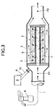
- FIG. 1 illustrates a first embodiment of the present invention.
- a metal case 2 is disposed partway along an exhaust system 1 leading to a diesel engine E.
- the case 2 houses a filter 3A for collecting particulates contained in the exhaust gas discharged from the diesel engine E.
- the filter 3A is of a fiber type formed by winding a fiber 7 around a bottomed perforated metal cylinder 6 which has, for example, its upstream end open and its downstream end closed.
- the fiber 7 is made of, for example, SiC.
- the exhaust gas discharged from the diesel engine E flows substantially uniformly from the inner periphery of the perforated metal cylinder 6 to the outer periphery of the fiber 7, the particulates contained in the exhaust gas being collected by the filter 3A substantially uniformly in the direction of the flow, which advantageously improves the removal efficiency when regenerating the filter 3A by burning and removing the particulates.
- an electromagnetic wave heating device 8 for burning and removing the particulates collected by the filter 3A, the device 8 including a microwave generator 9 and a waveguide 10 leading to the microwave generator 9.
- an electromagnetic wave shielding plate 11A for dividing the filter 3A into an upstream side filter section 4A and a downstream side filter section 5A is fixed within the case 2 so as to be disposed in a middle section of the filter 3A.
- the electromagnetic wave shielding plate 11A is formed by utilizing the property of microwaves that the microwaves guided from the microwave generator 9 to the interior of the case 2 via the waveguide 10 cannot pass through holes having a diameter that is smaller than the wavelength of the microwaves, for example, holes having a diameter of 50 mm or less.
- a plate having a large number of small holes such as, for example, a perforated metal plate is employed as the electromagnetic wave shielding plate 11A.
- the electromagnetic wave shielding plate 11A thereby prevents the microwaves from being transmitted from the upstream side filter section 4A to the downstream side filter section 5A.
- the pressure loss of the filter 3A increases as the amount of collected particulates increases during operation of the diesel engine E, the particulates collected by the filter 3A are burned and removed by means of the electromagnetic wave heating device 8.
- the filter 3A is divided into the upstream side filter section 4A and the downstream side filter section 5A within the case 2, and the electromagnetic wave heating device 8 is connected to the case 2 on the upstream side of the upstream side filter section 4A.
- the upstream side filter section 4A is heated by the electromagnetic wave heating device 8, and the particulates collected by the upstream side filter section 4A are burned and removed.
- the upstream side filter section 4A is heated by the electromagnetic wave heating device 8
- the upstream side filter section 4A is of the fiber type using SiC as in the first embodiment, it is known that the energy input by the electromagnetic wave heating device 8 can be converted into heat with substantially 100% efficiency.
- the SiC fiber 7 is directly heated by the electromagnetic wave heating device 8, and the particulates collected by the SiC fiber 7 can be directly burned and removed, thereby burning and removing the particulates collected by the upstream side filter section 4A with a high efficiency.
- the heat generated when the particulates are burned and converted into CO 2 and H 2 O is transmitted to the downstream side filter section 5A. Also transmitted to the downstream side filter section 5A is the heat generated in the upstream side filter section 4A by the microwaves from the electromagnetic wave heating device 8, thereby burning and removing the particulates collected by the downstream side filter section 5A.
- the electromagnetic wave heating device 8 only has to input energy sufficient to heat the upstream side filter section 4A, thus reducing the energy input by the electromagnetic wave heating device 8 and thereby achieving excellent energy efficiency. As a result, it becomes possible to reduce the size of the electromagnetic wave heating device 8.
- the electromagnetic wave shielding plate 11A is disposed between the upstream side and downstream side filter sections 4A and 5A, the microwaves from the electromagnetic wave heating device 8 can be applied effectively to the upstream side filter section 4A, thereby enhancing the energy efficiency.
- the total of the heat generated by burning of the particulates in the upstream side filter section 4A and transmitted to the downstream side filter section 5A, and the heat applied by the electromagnetic wave heating device 8 to the upstream side filter section 4A and transmitted to the downstream side filter section 5A, is required to be at a level that can maintain the temperature of the downstream side filter section 5A at or above the ignition temperature of the particulates. It is therefore necessary to set the volume ratio of the upstream side filter section 4A to the downstream side filter section 5A appropriately, and the maximum thermal efficiency can thus be obtained.
- a catalyst can be carried on the filter 3A, which can decrease the ignition temperature of the particulates, thus reducing the energy input by the electromagnetic wave heating device 8 and thereby achieving excellent energy efficiency.
- FIG. 2 illustrates a second embodiment of the present invention.
- a case 2 disposed partway along an exhaust system 1 leading to a diesel engine E houses a filter 3B for collecting particulates.
- This filter 3B is divided into an upstream side filter section 4B and a downstream side filter section 5B by means of an electromagnetic wave shielding plate 11B as in the first embodiment.
- the upstream side filter section 4B is of a fiber type formed by winding a fiber 7 made of SiC around a bottomed perforated metal cylinder 6' which has, for example, its upstream end open and its downstream end closed.
- the downstream side filter section 5B is of a wall flow type having a large number of through holes 12. The upstream ends and downstream ends of adjacent through holes 12 are alternately closed.
- the downstream side filter section 5B is made of, for example, cordierite having a pore size of 20 ⁇ m or less.
- An electromagnetic wave heating device 8 is connected to the case 2 on the upstream side of the upstream side filter section 4B.
- the cordierite forming the downstream side filter section 5B is less expensive than SiC, whereas SiC has a melting point higher than that of cordierite and is superior in terms of heat resistance.
- the upstream side filter section 4B has the advantage in that the collection efficiency can be set as desired by changing the amount of fiber 7 that is wound around it. It is therefore possible to achieve a reduction in cost by forming the upstream side filter section 4B, which is required to have a heat resistance, of the fiber type using the fiber 7 made of SiC, and forming the downstream side filter section 5B, which is less required to have a heat resistance, of the wall flow type using cordierite.
- the particulates collected by the filter 3B are burned and removed, it is only necessary to heat the upstream side filter section 4B by the electromagnetic wave heating device 8, as in the first embodiment.
- the heat generated by the burning of particulates in the upstream side filter section 4B and the heat generated in the upstream side filter section 4B by the microwaves from the electromagnetic wave heating device 8 are transmitted to the downstream side filter section 5B, so that it becomes possible to burn and remove the particulates collected by the downstream side filter section 5B. It is therefore possible to reduce the energy input by the electromagnetic wave heating device 8, achieve an excellent energy efficiency, and reduce the size of the electromagnetic wave heating device 8.
- the energy required for burning and removing particulates in the exhaust system of a 1.6 L diesel engine was compared between the particulate removal systems of the first and second embodiments, and a particulate removal system having a conventional structure as shown by a comparative example in FIG. 3 in which a filter 3 of the fiber type formed by winding a fiber 7 made of SiC around a bottomed perforated metal cylinder 6 is housed in a case 2 without dividing the filter 3 into two.
- the case 2 used had a diameter of 120 mm and a length of 142 mm, and the diesel engine E was operated at a vehicle speed of 60 km/h.
- a pressure P1 on the upstream side of the filters 3A, 3B, 3, a pressure P2 on the downstream side of the filters 3A, 3B, 3, and a temperature T in the upstream section of each of the filters 3A, 3B, 3 were detected; when P1 - P2 > 20 kPa, the power to the electromagnetic wave heating device 8 was turned ON; and when P1 - P2 ⁇ 0.5 kPa, the power to the electromagnetic wave heating device 8 was turned OFF.
- the electromagnetic wave heating device 8 required an energy of 140 kJ for burning and removing the particulates; in the particulate removal system of the second embodiment the electromagnetic wave heating device 8 required an energy of 123 kJ for burning and removing the particulates; and in the particulate removal system of the comparative example the electromagnetic wave heating device 8 required an energy of 204 kJ for burning and removing the particulates. That is, it has been confirmed that, in accordance with the particulate removal systems of the first and second embodiments, the energy required for burning and removing the particulates can be greatly reduced as compared with the conventional system.
- FIG. 4 illustrates a third embodiment of the present invention.
- a case 2 disposed partway along an exhaust system 1 leading to a diesel engine E houses a filter 3A divided into an upstream side filter section 4A and a downstream side filter section 5A, a catalyst 13 disposed on the upstream side of the upstream side filter section 4A, and an electromagnetic wave shielding plate 14 disposed between the catalyst 13 and the filter 3A.
- An electromagnetic wave heating device 8 is connected to the case 2 between the electromagnetic wave shielding plate 14 and the filter 3A.
- the same effects as in the first embodiment can be obtained. Moreover, since the exhaust gas temperature increases due to burning of unburned HCs and CO by the catalyst, an increase in the temperature of the filter 3A required for achieving a target temperature can be reduced as compared with the case where no catalyst is housed within the case 2, thereby heating the filter 3A with a higher efficiency. Since the catalyst 13 is also heated via the wall of the case 2 when heating the upstream side filter section 4A by means of the electromagnetic wave heating device 8, the catalyst 13 can be activated to improve the properties of the exhaust gas.
- the present invention is applied to a diesel engine E, but it is also possible to apply the present invention to a gasoline engine.
- a particulate removal system includes a case 2 provided partway along an exhaust system 1 leading to an engine E, a filter 3A that collects particulates contained in an exhaust gas, and an electromagnetic wave heating device 8 for burning the particulates collected by the filter 3A.
- the filter 3A is housed within the case 2, and the electromagnetic wave heating device 8 is connected to the case 2.
- the filter 3A is divided in two and arranged within the case 2 as an upstream side filter section 4A and a downstream side filter section 5A.
- the electromagnetic wave heating device 8 is connected to the case 2 on the upstream side of the upstream side filter section 4A.
Landscapes
- Engineering & Computer Science (AREA)
- Chemical & Material Sciences (AREA)
- Chemical Kinetics & Catalysis (AREA)
- Combustion & Propulsion (AREA)
- Mechanical Engineering (AREA)
- General Engineering & Computer Science (AREA)
- Health & Medical Sciences (AREA)
- Toxicology (AREA)
- Physics & Mathematics (AREA)
- Geometry (AREA)
- Processes For Solid Components From Exhaust (AREA)
- Exhaust Gas After Treatment (AREA)
- Filtering Materials (AREA)
- Filtering Of Dispersed Particles In Gases (AREA)
- Exhaust Gas Treatment By Means Of Catalyst (AREA)
Applications Claiming Priority (2)
| Application Number | Priority Date | Filing Date | Title |
|---|---|---|---|
| JP2002036298A JP2003239725A (ja) | 2002-02-14 | 2002-02-14 | パーティキュレート除去装置 |
| JP2002036298 | 2002-02-14 |
Publications (3)
| Publication Number | Publication Date |
|---|---|
| EP1336730A2 true EP1336730A2 (de) | 2003-08-20 |
| EP1336730A3 EP1336730A3 (de) | 2004-02-11 |
| EP1336730B1 EP1336730B1 (de) | 2007-03-28 |
Family
ID=27621413
Family Applications (1)
| Application Number | Title | Priority Date | Filing Date |
|---|---|---|---|
| EP03003042A Expired - Lifetime EP1336730B1 (de) | 2002-02-14 | 2003-02-12 | System zur Entfernung von Partikeln |
Country Status (3)
| Country | Link |
|---|---|
| EP (1) | EP1336730B1 (de) |
| JP (1) | JP2003239725A (de) |
| DE (1) | DE60312753T2 (de) |
Cited By (5)
| Publication number | Priority date | Publication date | Assignee | Title |
|---|---|---|---|---|
| CN102852598A (zh) * | 2011-06-29 | 2013-01-02 | 南京辉虎环保科技有限公司 | 附微波之引擎排气滤芯 |
| US20180008925A1 (en) * | 2016-07-08 | 2018-01-11 | Fujitsu Limited | Fine particle detector and exhaust gas purification apparatus |
| WO2019091755A1 (de) * | 2017-11-09 | 2019-05-16 | Continental Automotive Gmbh | System zur abgasbehandlung für ein kraftfahrzeug, verfahren und vorrichtung zum ermitteln eines zustands eines systems zur abgasbehandlung für ein kraftfahrzeug |
| US10576406B2 (en) | 2017-04-04 | 2020-03-03 | Fujitsu Limited | Exhaust purification device, internal combustion device, and power generation device |
| CN119633514A (zh) * | 2025-02-05 | 2025-03-18 | 江苏科海生物工程设备有限公司 | 一种化工废气处理净化设备 |
Families Citing this family (5)
| Publication number | Priority date | Publication date | Assignee | Title |
|---|---|---|---|---|
| JP4735341B2 (ja) * | 2006-03-06 | 2011-07-27 | 日産自動車株式会社 | エンジンの排気浄化装置 |
| JP2009240863A (ja) * | 2008-03-28 | 2009-10-22 | Nippon Spindle Mfg Co Ltd | フィルタ装置 |
| EP2987975B1 (de) * | 2014-08-23 | 2017-09-20 | Advanced Technology Emission Solutions Inc. | Katalysatorkonvertersystem und dazugehöriges steuerungsverfahren |
| JP6817134B2 (ja) * | 2017-04-17 | 2021-01-20 | 日本特殊陶業株式会社 | マイクロ波加熱用触媒材料、マイクロ波加熱用触媒体、及びマイクロ波加熱用触媒体の製造方法 |
| CN111412037A (zh) * | 2020-04-22 | 2020-07-14 | 扬州工业职业技术学院 | 一种基于微波加热再生的排气微粒捕集装置 |
Citations (2)
| Publication number | Priority date | Publication date | Assignee | Title |
|---|---|---|---|---|
| JPH06241020A (ja) | 1993-02-18 | 1994-08-30 | Toyota Motor Corp | 排気浄化装置 |
| JPH09241021A (ja) | 1996-03-11 | 1997-09-16 | Denki Kagaku Kogyo Kk | カルシウムアルミネートトライカーボネートハイドレート及びその合成方法 |
Family Cites Families (3)
| Publication number | Priority date | Publication date | Assignee | Title |
|---|---|---|---|---|
| US4346557A (en) * | 1980-05-07 | 1982-08-31 | General Motors Corporation | Incineration-cleanable composite diesel exhaust filter and vehicle equipped therewith |
| US5194078A (en) * | 1990-02-23 | 1993-03-16 | Matsushita Electric Industrial Co., Ltd. | Exhaust filter element and exhaust gas-treating apparatus |
| JPH06241022A (ja) * | 1993-02-18 | 1994-08-30 | Toyota Motor Corp | 排気浄化装置 |
-
2002
- 2002-02-14 JP JP2002036298A patent/JP2003239725A/ja not_active Withdrawn
-
2003
- 2003-02-12 EP EP03003042A patent/EP1336730B1/de not_active Expired - Lifetime
- 2003-02-12 DE DE60312753T patent/DE60312753T2/de not_active Expired - Fee Related
Patent Citations (2)
| Publication number | Priority date | Publication date | Assignee | Title |
|---|---|---|---|---|
| JPH06241020A (ja) | 1993-02-18 | 1994-08-30 | Toyota Motor Corp | 排気浄化装置 |
| JPH09241021A (ja) | 1996-03-11 | 1997-09-16 | Denki Kagaku Kogyo Kk | カルシウムアルミネートトライカーボネートハイドレート及びその合成方法 |
Cited By (6)
| Publication number | Priority date | Publication date | Assignee | Title |
|---|---|---|---|---|
| CN102852598A (zh) * | 2011-06-29 | 2013-01-02 | 南京辉虎环保科技有限公司 | 附微波之引擎排气滤芯 |
| US20180008925A1 (en) * | 2016-07-08 | 2018-01-11 | Fujitsu Limited | Fine particle detector and exhaust gas purification apparatus |
| US10850221B2 (en) * | 2016-07-08 | 2020-12-01 | Fujitsu Limited | Fine particle detector and exhaust gas purification apparatus |
| US10576406B2 (en) | 2017-04-04 | 2020-03-03 | Fujitsu Limited | Exhaust purification device, internal combustion device, and power generation device |
| WO2019091755A1 (de) * | 2017-11-09 | 2019-05-16 | Continental Automotive Gmbh | System zur abgasbehandlung für ein kraftfahrzeug, verfahren und vorrichtung zum ermitteln eines zustands eines systems zur abgasbehandlung für ein kraftfahrzeug |
| CN119633514A (zh) * | 2025-02-05 | 2025-03-18 | 江苏科海生物工程设备有限公司 | 一种化工废气处理净化设备 |
Also Published As
| Publication number | Publication date |
|---|---|
| EP1336730A3 (de) | 2004-02-11 |
| DE60312753T2 (de) | 2007-08-16 |
| DE60312753D1 (de) | 2007-05-10 |
| JP2003239725A (ja) | 2003-08-27 |
| EP1336730B1 (de) | 2007-03-28 |
Similar Documents
| Publication | Publication Date | Title |
|---|---|---|
| JP3378432B2 (ja) | ディーゼルエンジン用パティキュレートトラップ | |
| US4346557A (en) | Incineration-cleanable composite diesel exhaust filter and vehicle equipped therewith | |
| EP2180936B1 (de) | Einstellung der leistungsfähigkeit von partikelfiltern durch selektive verstopfung und verwendung von mehreren partikelfiltern zur verringerung von emissionen und verbesserung der thermischen robustheit | |
| US6447564B1 (en) | Regeneration system for an exhaust gas cleaning device | |
| US5144798A (en) | Regenerative particulate trap system for emission control | |
| US6709489B2 (en) | Microwave regenerated diesel particulate trap | |
| JPH0949421A (ja) | ディーゼルエンジン用パティキュレートトラップ | |
| EP1336730B1 (de) | System zur Entfernung von Partikeln | |
| CN1271318C (zh) | 用于过滤内燃机尾气中所含微粒的过滤体 | |
| WO1993018841A1 (en) | Ceramic filter construction and methods of filtering using such construction | |
| JPH09262414A (ja) | ディーゼルエンジン用パティキュレートトラップ | |
| JPH06257422A (ja) | ディーゼルエンジン用パティキュレートトラップ | |
| CN101397924A (zh) | 无线分区微粒物质过滤器再生控制系统 | |
| ZA200304232B (en) | Particulate filter for purifying exhaust gases of internal international combustion engines comprising hot spot ceramic ignitors. | |
| US20060156702A1 (en) | Method and apparatus for filtering exhaust particulates | |
| JP6539551B2 (ja) | 排ガス処理装置、触媒の昇温方法、ハニカム構造体の再生方法、及びアッシュ除去方法 | |
| US5782941A (en) | Particulate trap for diesel engine | |
| US20040099139A1 (en) | Carbon-concentrated microwave regenerated diesel particulate trap | |
| EP0837228A2 (de) | Abgasreiniger | |
| JP2008512594A (ja) | 内燃機関の排気ガス濾過構造体、及び関連の排気管路 | |
| JP2017047404A (ja) | 排ガス処理装置及びハニカム構造体の製造方法 | |
| JPS62149316A (ja) | 排ガスフイルタ− | |
| JP2000130150A (ja) | デイーゼル機関の排気微粒子フイルタ | |
| US20070044458A1 (en) | Exhaust particulate filter | |
| JPH06241022A (ja) | 排気浄化装置 |
Legal Events
| Date | Code | Title | Description |
|---|---|---|---|
| PUAI | Public reference made under article 153(3) epc to a published international application that has entered the european phase |
Free format text: ORIGINAL CODE: 0009012 |
|
| AK | Designated contracting states |
Designated state(s): AT BE BG CH CY CZ DE DK EE ES FI FR GB GR HU IE IT LI LU MC NL PT SE SI SK TR |
|
| AX | Request for extension of the european patent |
Extension state: AL LT LV MK RO |
|
| PUAL | Search report despatched |
Free format text: ORIGINAL CODE: 0009013 |
|
| AK | Designated contracting states |
Kind code of ref document: A3 Designated state(s): AT BE BG CH CY CZ DE DK EE ES FI FR GB GR HU IE IT LI LU MC NL PT SE SI SK TR |
|
| AX | Request for extension of the european patent |
Extension state: AL LT LV MK RO |
|
| RIC1 | Information provided on ipc code assigned before grant |
Ipc: 7F 01N 3/035 B Ipc: 7F 01N 3/022 B Ipc: 7F 01N 3/023 B Ipc: 7F 01N 3/028 A |
|
| 17P | Request for examination filed |
Effective date: 20040308 |
|
| AKX | Designation fees paid |
Designated state(s): DE FR GB |
|
| GRAP | Despatch of communication of intention to grant a patent |
Free format text: ORIGINAL CODE: EPIDOSNIGR1 |
|
| GRAS | Grant fee paid |
Free format text: ORIGINAL CODE: EPIDOSNIGR3 |
|
| GRAA | (expected) grant |
Free format text: ORIGINAL CODE: 0009210 |
|
| AK | Designated contracting states |
Kind code of ref document: B1 Designated state(s): DE FR GB |
|
| REG | Reference to a national code |
Ref country code: GB Ref legal event code: FG4D |
|
| REF | Corresponds to: |
Ref document number: 60312753 Country of ref document: DE Date of ref document: 20070510 Kind code of ref document: P |
|
| PLBE | No opposition filed within time limit |
Free format text: ORIGINAL CODE: 0009261 |
|
| STAA | Information on the status of an ep patent application or granted ep patent |
Free format text: STATUS: NO OPPOSITION FILED WITHIN TIME LIMIT |
|
| 26N | No opposition filed |
Effective date: 20080102 |
|
| PGFP | Annual fee paid to national office [announced via postgrant information from national office to epo] |
Ref country code: GB Payment date: 20080206 Year of fee payment: 6 Ref country code: DE Payment date: 20080207 Year of fee payment: 6 |
|
| PGFP | Annual fee paid to national office [announced via postgrant information from national office to epo] |
Ref country code: FR Payment date: 20080208 Year of fee payment: 6 |
|
| GBPC | Gb: european patent ceased through non-payment of renewal fee |
Effective date: 20090212 |
|
| REG | Reference to a national code |
Ref country code: FR Ref legal event code: ST Effective date: 20091030 |
|
| PG25 | Lapsed in a contracting state [announced via postgrant information from national office to epo] |
Ref country code: DE Free format text: LAPSE BECAUSE OF NON-PAYMENT OF DUE FEES Effective date: 20090901 |
|
| PG25 | Lapsed in a contracting state [announced via postgrant information from national office to epo] |
Ref country code: GB Free format text: LAPSE BECAUSE OF NON-PAYMENT OF DUE FEES Effective date: 20090212 Ref country code: FR Free format text: LAPSE BECAUSE OF NON-PAYMENT OF DUE FEES Effective date: 20090302 |