EP1336554A1 - Method and apparatus for assembling a radiator module for an automobile - Google Patents
Method and apparatus for assembling a radiator module for an automobile Download PDFInfo
- Publication number
- EP1336554A1 EP1336554A1 EP03002020A EP03002020A EP1336554A1 EP 1336554 A1 EP1336554 A1 EP 1336554A1 EP 03002020 A EP03002020 A EP 03002020A EP 03002020 A EP03002020 A EP 03002020A EP 1336554 A1 EP1336554 A1 EP 1336554A1
- Authority
- EP
- European Patent Office
- Prior art keywords
- radiator module
- positioning
- assembling
- radiator
- hand body
- Prior art date
- Legal status (The legal status is an assumption and is not a legal conclusion. Google has not performed a legal analysis and makes no representation as to the accuracy of the status listed.)
- Granted
Links
- 238000000034 method Methods 0.000 title claims description 31
- 230000002787 reinforcement Effects 0.000 claims abstract description 41
- 230000003028 elevating effect Effects 0.000 claims abstract description 36
- 230000007246 mechanism Effects 0.000 claims abstract description 25
- 238000010586 diagram Methods 0.000 description 4
- 238000001816 cooling Methods 0.000 description 1
- 230000002452 interceptive effect Effects 0.000 description 1
- 230000009191 jumping Effects 0.000 description 1
- 238000000926 separation method Methods 0.000 description 1
Images



Classifications
-
- B—PERFORMING OPERATIONS; TRANSPORTING
- B62—LAND VEHICLES FOR TRAVELLING OTHERWISE THAN ON RAILS
- B62D—MOTOR VEHICLES; TRAILERS
- B62D65/00—Designing, manufacturing, e.g. assembling, facilitating disassembly, or structurally modifying motor vehicles or trailers, not otherwise provided for
-
- B—PERFORMING OPERATIONS; TRANSPORTING
- B62—LAND VEHICLES FOR TRAVELLING OTHERWISE THAN ON RAILS
- B62D—MOTOR VEHICLES; TRAILERS
- B62D65/00—Designing, manufacturing, e.g. assembling, facilitating disassembly, or structurally modifying motor vehicles or trailers, not otherwise provided for
- B62D65/02—Joining sub-units or components to, or positioning sub-units or components with respect to, body shell or other sub-units or components
-
- Y—GENERAL TAGGING OF NEW TECHNOLOGICAL DEVELOPMENTS; GENERAL TAGGING OF CROSS-SECTIONAL TECHNOLOGIES SPANNING OVER SEVERAL SECTIONS OF THE IPC; TECHNICAL SUBJECTS COVERED BY FORMER USPC CROSS-REFERENCE ART COLLECTIONS [XRACs] AND DIGESTS
- Y10—TECHNICAL SUBJECTS COVERED BY FORMER USPC
- Y10S—TECHNICAL SUBJECTS COVERED BY FORMER USPC CROSS-REFERENCE ART COLLECTIONS [XRACs] AND DIGESTS
- Y10S269/00—Work holders
- Y10S269/909—Work holder for specific work
-
- Y—GENERAL TAGGING OF NEW TECHNOLOGICAL DEVELOPMENTS; GENERAL TAGGING OF CROSS-SECTIONAL TECHNOLOGIES SPANNING OVER SEVERAL SECTIONS OF THE IPC; TECHNICAL SUBJECTS COVERED BY FORMER USPC CROSS-REFERENCE ART COLLECTIONS [XRACs] AND DIGESTS
- Y10—TECHNICAL SUBJECTS COVERED BY FORMER USPC
- Y10T—TECHNICAL SUBJECTS COVERED BY FORMER US CLASSIFICATION
- Y10T29/00—Metal working
- Y10T29/49—Method of mechanical manufacture
- Y10T29/49826—Assembling or joining
-
- Y—GENERAL TAGGING OF NEW TECHNOLOGICAL DEVELOPMENTS; GENERAL TAGGING OF CROSS-SECTIONAL TECHNOLOGIES SPANNING OVER SEVERAL SECTIONS OF THE IPC; TECHNICAL SUBJECTS COVERED BY FORMER USPC CROSS-REFERENCE ART COLLECTIONS [XRACs] AND DIGESTS
- Y10—TECHNICAL SUBJECTS COVERED BY FORMER USPC
- Y10T—TECHNICAL SUBJECTS COVERED BY FORMER US CLASSIFICATION
- Y10T29/00—Metal working
- Y10T29/49—Method of mechanical manufacture
- Y10T29/49998—Work holding
-
- Y—GENERAL TAGGING OF NEW TECHNOLOGICAL DEVELOPMENTS; GENERAL TAGGING OF CROSS-SECTIONAL TECHNOLOGIES SPANNING OVER SEVERAL SECTIONS OF THE IPC; TECHNICAL SUBJECTS COVERED BY FORMER USPC CROSS-REFERENCE ART COLLECTIONS [XRACs] AND DIGESTS
- Y10—TECHNICAL SUBJECTS COVERED BY FORMER USPC
- Y10T—TECHNICAL SUBJECTS COVERED BY FORMER US CLASSIFICATION
- Y10T29/00—Metal working
- Y10T29/51—Plural diverse manufacturing apparatus including means for metal shaping or assembling
- Y10T29/5191—Assembly
-
- Y—GENERAL TAGGING OF NEW TECHNOLOGICAL DEVELOPMENTS; GENERAL TAGGING OF CROSS-SECTIONAL TECHNOLOGIES SPANNING OVER SEVERAL SECTIONS OF THE IPC; TECHNICAL SUBJECTS COVERED BY FORMER USPC CROSS-REFERENCE ART COLLECTIONS [XRACs] AND DIGESTS
- Y10—TECHNICAL SUBJECTS COVERED BY FORMER USPC
- Y10T—TECHNICAL SUBJECTS COVERED BY FORMER US CLASSIFICATION
- Y10T29/00—Metal working
- Y10T29/53—Means to assemble or disassemble
Definitions
- the present invention relates to a method for assembling a radiator module for an automobile and to an apparatus for assembling the same, and more particularly to a technique for assembling a radiator module containing a radiator and a radiator shroud where a bumper reinforcement is fixed.
- JP Kokai 7-69244 discloses a method for assembling a front part of an automobile using connecting robot comprising the first step of setting a cooling parts module (radiator module) and an exterior module such as bumper to an assembling jig mounted on a bench, the second step of connecting both of the modules to each other by a connecting robot, the third step of mounting both of the modules to the automobile body by a mounting robot. It also discloses such an assembling jig.
- JP Kokai 2001-30133 discloses a work positioning apparatus, in which a radiator module such as the one just described is positioned and fixed to a work holding device, the work holding device is set in front of an automobile body, a positioning guide pin extending backward from the work holding device horizontally is inserted into positioning guide holes of the right and the left front side members of the automobile body, and the work holding device and the radiator module are conveyed backward to assemble a front end module to the automobile body.
- front end part of an automobile body has a bumper reinforcement, which connects to the front ends of the right and the left front side frames each other.
- a bumper reinforcement which connects to the front ends of the right and the left front side frames each other.
- the work positioning technique described in the latter of above-identified publications employs a process where a radiator module is conveyed horizontally from the front of a automobile body to the back thereof and is assembled thereto.
- a radiator module is conveyed horizontally from the front of a automobile body to the back thereof and is assembled thereto.
- the radiator module when the radiator module is conveyed horizontally from the front and is assembled to the automobile body, there is a possibility for the radiator module to interfere with the bumper reinforcement at the front end of the automobile body, or the height of the bumper reinforcement position imposes restriction on the process.
- the first embodiment of the present invention is a method for mounting a radiator module containing a radiator and a radiator shroud in the vicinity of the back side of a bumper reinforcement and assembling the radiator module to an automobile body while the bumper reinforcement is assembled to connect the front ends of the right and the left front side frames of the automobile body to each other, the method comprising the step of providing an assembling jig having a jig base member, an elevating body capable of being elevated with respect to the jig base member, a hand body connected to the elevating body, and a holding mechanism for holding the radiator module when positioning the radiator module on the hand body; the first step of connecting the jig base member to an arm member of an outside conveyor for carrying the assembly jig and the radiator module and holding the radiator module on the hand body by way of the holding mechanism; the second step of moving the assembling jig and the radiator module to a position for subsequent mounting to the automobile body; the third step of positioning the jig base member next to the bumper reinforcement by way of the positioning member;
- an air balancer equipment can be used as the "conveyor” or "conveying means” just described.
- the radiator module is assembled while a bumper reinforcement is assembled to connect the front ends of the right and the left front side frames to each other so that the structure of the front part of the automobile body is fixed, the radiator module is assembled efficiently with high precision.
- the jig base member is connected to an arm member of an outside conveyor, and the radiator module is held on the hand body by way of the holding mechanism.
- the assembling jig and the radiator module are moved to a position for subsequent mounting to the automobile body.
- the jig base member is positioned to the bumper reinforcement by way of the positioning member.
- the elevating body, the hand body and the radiator module are moved downwardly from the upper position with respect to the jig base member, and a pair of the right and the left positioning members of the hand body are positioned to right and left fender parts of the automobile body, respectively.
- the hand body is positioned to the fender part efficiently with high precision.
- the radiator module is held by the hand body with high precision, by positioning the hand body to the fender part precisely, the radiator module is positioned precisely with respect to the fender part of the front side frame.
- the second embodiment of the present invention is, in the method for assembling a radiator module for an automobile of the first embodiment, the hand body of the assembling jig is connected to the elevating body rotatably around an axis that is positioned in a widthwise direction of the automobile body, and in the forth step, the hand body and the radiator module are moved downwardly to a predetermined non-interference down position with keeping their forward-inclining attitude, then the hand body and the radiator module are set to their normal attitude, and they are moved downwardly to a predetermined down end and a pair of the right and the left positioning members of the hand body are positioned to right and left fender parts of the automobile body, respectively.
- the radiator module When the jig base member is positioned to the bumper reinforcement, there is a possibility for the radiator module to interfere with the automobile body.
- the hand body and the radiator module are moved downwardly to a predetermined non-interference down position with keeping their forward-inclining attitude, then the hand body and the radiator module are set to their normal attitude, and they are moved downwardly to a predetermined down end and the right and the left positioning members of the hand body are positioned to right and left fender parts of the automobile body, respectively.
- the third embodiment of the present invention is, in the method for assembling a radiator module for an automobile of the first embodiment, in the forth step, when the pair of the right and the left positioning members of the hand body are positioned to right and left fender parts of the automobile body, a positioning standard member of the hand body is positioned to the front side frame.
- a positioning standard member of the hand body is positioned to the front side frame.
- the fourth embodiment of the present invention is, in the method for assembling a radiator module for an automobile of the first embodiment, the method comprising the fifth step of fixing a plurality of parts of the radiator module to be connected to the parts for connection of right and left fender parts of the automobile body and to the part for connection at the vicinity of the front side frame, respectively; and the sixth step of separating the hand body from the radiator module by releasing the holding mechanism.
- the hand body By positioning the hand body to the automobile body with high precision as just described, after the radiator module is positioned precisely to the automobile body by way of the hand body, in the fifth step, a plurality of parts of the radiator module to be connected are fixed to the parts for connection of right and left fender parts of the automobile body and to the part for connection at the vicinity of the front side frame, respectively. Then, in the sixth step, the hand body is separated from the radiator module by releasing the holding mechanism.
- the fifth embodiment of the present invention is, in the method for assembling a radiator module for an automobile of the fourth embodiment, supporting strength for supporting the assembling jig and the radiator module by an arm member of the conveyor is reduced after the fourth step and before the fifth step.
- the supporting strength for supporting the objects such as work by the arm member can be adjusted by a driving cylinder for balancing the load.
- the supporting strength of the arm member of the conveyor is set to be equal to the sum of the weights of the assembling jig and the radiator module until the assembling jig and the radiator module are moved to the mounting position. Then, supporting strength for supporting the assembling jig and the radiator module by an arm member of the conveyor is reduced after the fourth step and before the fifth step, so that the status of the assembling jig and the radiator module positioned to the automobile body is stabilized, and the plurality of the parts of the radiator module to be connected can intimately contact with each of the parts for connection easily.
- the sixth embodiment of the present invention is, in the method for assembling a radiator module for an automobile of the fourth embodiment, in the sixth step, the supporting strength for supporting the assembling jig by an arm member of the conveyor is reduced by the weight of the radiator module at the time of the release of the holding mechanism.
- the arm member can abruptly jump. Such abrupt jump of the arm member can be avoided by reducing the supporting strength for supporting the assembling jig by an arm member by the weight of the radiator module.
- the seventh embodiment of the present invention is, in the method for assembling a radiator module for an automobile of the first embodiment, the radiator module contains a condenser for an air conditioner in addition to the radiator.
- a condenser for an air conditioner can be assembled together with a radiator as a module.
- the eighth embodiment of the present invention is an apparatus for assembling a radiator module to the front end of an automobile body, the apparatus comprising a conveying means for carrying the assembly jig and the radiator module, the conveying means having an arm member; a jig base member which is connectable to the arm member; an elevating body which can be elevated on the jig base member by way of a guide rod, and driving means for elevating the elevating body; a hand body which is rotatable around an axis that is positioned in a widthwise direction of the automobile body on the elevating body, and driving means for rotating the hand body; a first positioning member which is provided on the hand body and is engagable to and disengagable from a positioning hole at the top end of the radiator module from above; a second positioning member which is provided on the hand body and is engagable to and disengagable from a positioning hole at the front end of the radiator module from front, and driving means for driving the second positioning member to engage and disengage the positioning hole
- the jig base member is connected to the arm member of the outside conveying means, and the jig base member is moved to the radiator module so that the radiator module is held by the hand body.
- the radiator module is held by engaging the first positioning member on the hand body to the positioning hole at the top end of the radiator module from above, and engaging the second positioning member on the hand body to the positioning hole at the front end of the radiator module.
- the radiator module supported by the jig base member by way of the elevating body and the hand body is moved to the mounting position at the front end of the automobile body by the arm member of the conveying means.
- the hand body and the radiator module is elevated by the driving means for elevation by way of the elevating body, or according to the necessity, the hand body and the radiator module is inclined to forward by the driving means for rotation.
- the jig base member is moved downwardly by the arm member toward the bumper reinforcement, and the third positioning member on the jig base member and is engaged to the positioning hole of a bumper reinforcement from above.
- the hand body and the radiator module are moved downwardly to a predetermined down position by the driving means for elevation with keeping their forward-inclining attitude. Then the hand body and the radiator module are set to their normal attitude, they are moved downwardly to a predetermined down end, and the fourth positioning member on the hand body and is engaged to the standard hole of a front side frame from above.
- the radiator module which has been positioned to the hand body by way of the first and the second positioning members will be positioned to the automobile body with high precision.
- FIGS. 1 to 5 are diagrams showing the situation where the radiator module is assembled to the radiator module assembling apparatus
- FIGS. 6 to 8 are diagrams showing the air balancer equipment for the conveyor
- FIGS. 9 to 13 are diagrams showing the situation where the radiator module assembling apparatus and the radiator module are supported by the air balancer equipment, and thus the radiator module is assembled to the front end part of the automobile body.
- the directions of frond, back, right and left denote corresponding directions with respect to the automobile body (see FIGS. 9 to 13).
- Radiator module 1 is a module assembled from a radiator for an automobile, a condenser for an air conditioner and a radiator shroud, although the description for the radiator itself is omitted in the radiator module 1 shown in the drawing.
- This radiator module 1 is assembled in the vicinity of the back side of bumper reinforcement 3, in the situation where the bumper reinforcement 3 has been assembled to the front end of the automobile to connect the front ends of the right and the left front side frames 2 to each other.
- This radiator module assembling apparatus 10 (hereinafter called “assembling jig") has, as major members, such as jig base member 11, cylinder for elevation (driving means for elevation) 12, a pair of guide rods 13, elevating body 14, and hand body 16 supported by horizontal spindle 15 directed to the car width direction.
- major members such as jig base member 11, cylinder for elevation (driving means for elevation) 12, a pair of guide rods 13, elevating body 14, and hand body 16 supported by horizontal spindle 15 directed to the car width direction.
- Jig base member 11 is bolted to hanging member 56 connected to arm member 54 of outside air balancer equipment 50 described afterward, and assembling jig 10 and radiator module 1 set thereto are supported by air balancer equipment 50 and conveyed.
- Jig base member 11 has bottom plate 21, right and left side plates, back plate 22, a pair of bracket 23 at both sides of cylinder for elevation 12.
- Crosspiece 24 having square U-shaped cross-section is fixed at the top of back plate 22, and a pair of guide rods 13 are inserted into the guide holes of a pair of guide pieces 24a formed such that they project to forward from crosspiece 24, thus the vicinity of the bottom end of guide rod 13 is supported.
- a pair of right and left pin supporting plates 25 having L-shaped cross-section are fixed to crosspiece 24, and to the pair of pin supporting plates 25, positioning pins (third positioning member) 26, which are engagable to and disengagable from a pair of right and left positioning hole (not shown) of bumper reinforcement 3 of the automobile from above, are fixed, respectively.
- the bottom ends of the pair of guide rods 13 are welded to bottom plate 21 by way of cylinder body and supported by the pair of guide pieces 24a.
- the top ends of the pair of guide rods 13 are connected to hanging member 56.
- Cylinder for elevation 12 consisting of an air cylinder is disposed vertically with upside down to the center of bottom plate 21 of jig base member 11, and a piston rod extending downward from cylinder body 12a is connected to the top surface of bottom plate 21.
- Elevating body 14 has horizontal member 27, a pair of arm members 28 extending obliquely up behind from horizontal member 27, and a pair of the parts to be guided 29 which are provided in the vicinity of the lower end of the pair of arm members 28and externally engaged to the pair of guide rods 13 slidably.
- Horizontal member 27 of elevating body 14 is connected to the midsection of cylinder body 12a of cylinder for elevation 12 by way of a pair of connecting members 27a, and elevating body 14 goes up when the rod of cylinder for elevation 12 is extended and it goes down when the rod is pulled back.
- Hand body 16 serves for assembling radiator module 1 by holding the module, and it is connected rotatably around spindle 15 directed to the car with direction to the top end of a pair of arm members 28 of elevating body 14.
- Hand body 16 has such as holding plate 30 corresponding to the top end of radiator module 1, a pair of right and left projecting parts 31 extending obliquely and horizontally behind from both of the right and the left ends of holding plate 30, shelf member 32 which extends right and left at front and below of holding plate 30 and is fixed to holding plate 30 by four connecting members 33, positioning pin (first positioning member) 34 which projects from the bottom surface of holding plate 30 and is engagable to and disengagable from three positioning holes at the top end of radiator module 1 from above, a pair of positioning pin mechanisms 35 provided at both right and left ends of shelf member 32, a pair of positioning pins (fourth positioning member) 36 which project from the back ends of a pair of right and left projecting parts 31 and is engagable to and disengagable from a pair of positioning standard holes of a fender part 4 from above, and frame standard pin (frame standard member) 20 which projects from the bottom surface of the right end side of shelf member 32.
- positioning pin first positioning member
- first positioning pin
- Each of positioning pin mechanisms 35 has such as a pair of upper and lower guide blocks 38 and cylinder for engage and disengage (driving means for engage and disengage) 37 disposed and fixed on shelf plate 32, pin holding plates 39, 40 which are capable of facing to the front face of both ends of radiator module 1 and are connected to the tip of the piston rod of cylinder for engage and disengage 37, positioning pin (second positioning member) 41 which project backward from the back side of pin holding plates 39, 40 and is engagable to and disengagable from a positioning hole at the front end of radiator module 1, and a pair of guide rods 38a which are fixed to the top and the bottom of pin holding plates 39, 40 and are inserted respectively into a pair of guide blocks 38.
- the cylinder body of cylinder for engage and disengage 37 and the pair of guide blocks 38 are fixed to shelf member 32.
- radiator module 1 When radiator module 1 is positioned to and held by hand body 16, hand body 16 is moved downwardly from the upper position with respect to radiator module 1, three positioning pins 34 at the lower part of holding plate 30 are engaged to three positioning holes at the top end of the radiator module 1 from above respectively, then a pair of pin holding plates 39, 40 are moved backward by cylinder for engage and disengage 37 of the pair of positioning pin mechanisms 35, thus the pair of positioning pins 41 are horizontally engaged to a pair of positioning holes at the front end of the radiator module 1 from front.
- those such as above-described holding plate 30, three positioning pins 34 and a pair of positioning pin mechanisms 35 correspond to the holding mechanism for holding radiator module 1 with positioning it to hand body 16.
- the end of the cylinder body of cylinder for rotation 46 is rotatably connected to supporting member 47 hooked to a pair of arm member 28 by way of the projecting piece at the side of the end and a pin member and a pair of projecting pieces at the side of supporting member 47.
- the tip of piston rod 46a of cylinder for rotation 46 is connected by pin to arm member 15a projecting from spindle 15.
- piston rod 46a of cylinder for rotation 46 is extended, and radiator module 1 held by hand body 16 has almost vertical normal attitude (attitude for being assembled to the automobile body).
- spindle 15 rotates so that hand body 16 has forward-inclining attitude, and that radiator module 1 held by hand body 16 has forward-inclining attitude.
- a pair of positioning pins project from the bottom surface of the back ends of a pair of projecting parts 31, and frame standard pin (frame standard member) 20, which is engagable to and disengagable from a positioning standard hole of front side frame 2 in the right side of the automobile body from above, projects downward from the bottom surface of the right end side of shelf member 32.
- Air balancer equipment (See FIGS. 6 to 8)
- Air balancer equipment 50 is an equipment for conveying assembling jig 10 which holds radiator module 1 to a mounting position at an automobile body and for holding assembling jig 10 and radiator module 1 while they are assembled.
- Air balancer equipment 50 is an air balance equipment having an ordinal structure, and corresponds to the conveyor.
- air balancer equipment 50 has such as base body 51 as a base, column body 52 standing on the base body 51, arm supporting member 53 connected and fixed to the top of the column body 52, arm member 54 which contains two pairs of parallel link mechanisms connected to the arm supporting member 53, connecting head member 55 at the tip of the arm member 54, and hanging member 56 which is connected to the connecting head member 55 and is extended to be bolted to jig base member 11 of assembling jig 10.
- outrigger 51a Provided at the vicinity of each of the four corners of base body 51 is outrigger 51a, and arm supporting member 53 is rotatable horizontally in 180 degrees with respect to column body 52.
- hanging member 56 just described has nearly gate-shape, the center of the beam part at the upper end is bolted to connecting head member 55, and the lower ends of a pair of gate-shape legs are bolted to a pair of bracket 23 in jig base member 11 of assembling jig 10.
- assembling jig 10 is only schematically shown in FIG. 6.
- arm supporting member 53 of air balancer equipment 50 are body board 53a, air cylinder for drive 57 standing upside down, and air pressure differential-type balancer 58 which controls supporting strength (the strength for supporting an object) for supporting at the tip of arm member 54 by controlling the air pressure of air cylinder for drive 57 through control valve 58a.
- Fulcrum connecting member 53b for connecting the fulcrum of arm member 54 so that the position of the fulcrum is selected is provided at the lower part of body board 53a.
- Base terminal fulcrum guide part 53c for guiding the base terminal fulcrum of arm member 54 to be connected to piston rod 57a of air cylinder for drive 57 is provided at the upper part of body board 53, so that the base terminal fulcrum is guided by changing its position up and down.
- Balance weight 59 is provided at the base terminal of main arm 54a of arm member 54.
- the air balancer equipment 50 controls the air pressure of cylinder for drive 57 by air pressure differential-type balancer 58 in response to the angle or the attitude of arm member 54 which changes according to the position of the object hung such as work. It also controls the amount of extension of piston rod 57a of air cylinder for drive 57. Thus, it can support the whole weight of the object hung at the tip of arm member 54, and control the supporting strength for hanging the object at the tip of arm member 54 according to the command from control panel 61 described afterward.
- control unit 60 having microcomputer, I/O and plurality of driving circuits is provided.
- control panel 61 To the control unit 60, control panel 61, weight sensor 62 which can detect the weight of the object hung, and control valve 58a of differential pressure-type balancer 58 are connected.
- the weights of assembling jig 10 and radiator module 1 supported thereby are detected by weight sensor 62 of air balancer equipment 50 and are memorized by control unit 60, and thus setup is made so that the total weight is hung and supported by arm member 54 of air balancer equipment 50.
- radiator module 1 is positioned to and held by hand body 16.
- hand body 16 is kept in almost vertical as its normal attitude.
- Holding plate 30 of hand body 16 is faced to the upper part of radiator module 1.
- Assembling jig 10 is moved downwardly from above toward radiator module 1.
- three positioning pins 34 provided on holding plate 30 are engaged to three positioning holes at the upper end of radiator module 1.
- hand body 16 and radiator module 1 are moved downwardly to a predetermined down end, which is detected by proximity switch 64.
- Positioning is made by engaging a pair of right and left positioning pins 36 at right and left projecting part 31 of hand body 16 to the positioning holes of right and left fender parts 4.
- frame standard pin 20 provided on shelf member 32 is engaged to the positioning standard hole at front side frame of the right side.
- the plurality of parts to be connected 1a, 1b are a pair of parts to be connected 1a at both right and left ends of shroud upper of radiator module 1 and a pair of parts to be connected 1b at both right and left ends of the front end of radiator shroud which is connected to bracket for fixing shroud (connecting part) 2a provided at the front ends of right and left front side frames 2.
- a pair of positioning pins 41 are disengaged from radiator module 1.
- elevating body 14 and hand body 16 are elevated by around 5cm, and by disengaging three positioning pins 34 from radiator module 1, hand body 16 is separated from radiator module 1.
- arm member 54 is manually moved to the original position of the conveyer, and the piston rod of cylinder for elevation 12 is pulled back and switched to the initial status, and thus they will be on stand by until next assembly of radiator module 1.
- radiator module is assembled while bumper reinforcement 3 is assembled to connect the front ends of the right and the left front side frames 2 of the automobile body to each other so that the structure of the front part of the automobile body is fixed, the radiator module will be assembled efficiently with high precision.
- jig base member 11 is positioned to bumper reinforcement 3 by positioning pin 26, jig base member 11 will be positioned to the automobile body with high precision by using bumper reinforcement 3 effectively.
- radiator module 1 is held by hand body 16 with high precision, by positioning hand body 16 precisely to fender part 4, radiator module 1 will be positioned precisely with respect to fender part 4 and front side frame 2.
- radiator module 1 will be positioned precisely to right and left fender parts 4. Owing to the pair of right and left positioning pins 36 of hand body 16 and frame standard pin 20, hand body 16 is positioned to the automobile body by the three different points, and thus hand body 16 will be positioned to the automobile body with high precision.
- a pair of parts to be connected 1a, 1b at both right and left ends of shroud upper of radiator module 1 are fixed to connecting parts of right and left fender parts 4 and to connecting bracket 2a at the vicinity of the front ends of front side frames 2, respectively.
- a pair of positioning pins 41 of a pair of positioning pin mechanisms 35 are disengaged from the positioning holes of radiator module 1, and three positioning pins 34 on holding plate 30 of hand body 16 are disengaged from the positioning holes of radiator module 1, so that hand body 16 is separated from radiator module 1.
- the positioning status of assembling jig 10 and radiator module 1 with respect to the automobile body will be stabilized, and each of the plurality of parts to be connected 1a, 1b of radiator module 1 will easily intimately contact, with the parts for connection on the side of the automobile body.
- radiator module 1 Since assembling jig 10 and radiator module 1 are hung by air balancer equipment 50, if the supporting strength of arm member 54 was not adjusted, and thus the weight of radiator module 1 suddenly stopped acting on arm member 54 due to the release of the holding on hand body 16, arm member member 54 would abruptly jump. However, in the seventh step, by reducing the supporting strength for supporting assembling jig 10 by arm member 54 by the weight of radiator module1, such abrupt jump of arm member 54 will be avoided. In this connection, since radiator module 1 contains a condenser for an air conditioner in addition to the radiator, the condenser for an air conditioner will be assembled together with the radiator as a module.
- radiator module 1 will be efficiently positioned to and held by hand body 16 with high precision.
- jig base member 11 will be efficiently positioned to bumper reinforcement 3 with high precision.
- hand body 16 is positioned precisely to the automobile body by a pair of positioning pins 36 of hand body 16 and frame standard pin 20, and thus in that situation, radiator module 1 will be efficiently assembled by way of assembling jig with high precision.
- the radiator module since the radiator module is assembled while the bumper reinforcement is assembled to connect the front ends of the right and the left front side frames of the automobile body to each other so that the structure of the front part of the automobile body is fixed, the radiator module will be assembled efficiently with high precision.
- the jig base member since the jig base member is positioned to the bumper reinforcement by way of the positioning member, the jig base member will be positioned to the automobile body with high precision by using the bumper reinforcement effectively.
- the elevating body, hand body and radiator module are moved downwardly from the upper position with respect to jig base member, and a pair of the right and the left positioning members of the hand body are positioned to right and left fender parts of the automobile body, respectively, the hand body will be positioned to the fender part with high precision. Therefore, by holding the radiator module by the hand body with high precision, if the hand body is positioned precisely to fender part, the radiator module will be positioned precisely with respect to the fender part and the front side frame.
- the hand body will be positioned precisely to the right and left fender parts with avoiding the interference between the radiator module and the automobile body.
- the hand body is positioned to the automobile body by the three different points, and thus is positioned to the automobile body with high precision.
- each of the parts to be connected of the fender of the radiator module will be fixed to the parts for connection of right and left fender parts of the automobile body and to the part for connection at the vicinity of the front side frame, and then, the hand body will be separated from the radiator module by releasing the holding mechanism.
- the positioning status of the assembling jig and the radiator module with respect to the automobile body will be stabilized, and the plurality of the parts to be connected of the radiator module will intimately contact with each of the parts for connection easily.
- the radiator module contains a condenser for an air conditioner in addition to the radiator, the condenser for an air conditioner will be assembled together with the radiator as a module.
- the apparatus for assembling a radiator module to the front end of an automobile body has such as a conveying means for carrying the assembly jig and the radiator module, the conveying means having an arm member; a jig base member which is connectable to the arm member; an elevating body which can be elevated on the jig base member by way of a guide rod, and driving means for elevating the elevating body; a hand body which is rotatable around an axis that is positioned in a widthwise direction of the automobile body on the elevating body, and driving means for rotating the hand body; a first positioning member which is provided on the hand body and is engagable to and disengagable from a positioning hole at the top end of the radiator module from above; a second positioning member which is provided on the hand body and is engagable to and disengagable from a positioning hole at the front end of the radiator module from front, and driving means for driving the second positioning member to engage and disengage the positioning hole;
- the radiator module will be assembled on the hand body with high precision by way of the first and the second positioning members of the and body and driving means for driving the second positioning member to engage and disengage.
- the jig base member will be precisely positioned to the bumper reinforcement by way of the third positioning member of the jig base member.
- the hand body will be positioned to the fender part and the front side frame with high precision by way of the fourth positioning member and the frame standard member.
- the radiator module will be positioned precisely and effectively with respect to the automobile body.
Landscapes
- Engineering & Computer Science (AREA)
- Manufacturing & Machinery (AREA)
- Chemical & Material Sciences (AREA)
- Combustion & Propulsion (AREA)
- Transportation (AREA)
- Mechanical Engineering (AREA)
- Automobile Manufacture Line, Endless Track Vehicle, Trailer (AREA)
- Automatic Assembly (AREA)
Abstract
Description
- The present invention relates to a method for assembling a radiator module for an automobile and to an apparatus for assembling the same, and more particularly to a technique for assembling a radiator module containing a radiator and a radiator shroud where a bumper reinforcement is fixed.
- These days, it has been widely employed to assemble equipments and decorative for an automobile to an automobile body efficiently after modularizing them. For example, Japanese Patent Unexamined Publication (JP Kokai) 7-69244 discloses a method for assembling a front part of an automobile using connecting robot comprising the first step of setting a cooling parts module (radiator module) and an exterior module such as bumper to an assembling jig mounted on a bench, the second step of connecting both of the modules to each other by a connecting robot, the third step of mounting both of the modules to the automobile body by a mounting robot. It also discloses such an assembling jig.
- On the other hand, Japanese Patent Unexamined Publication (JP Kokai) 2001-30133 discloses a work positioning apparatus, in which a radiator module such as the one just described is positioned and fixed to a work holding device, the work holding device is set in front of an automobile body, a positioning guide pin extending backward from the work holding device horizontally is inserted into positioning guide holes of the right and the left front side members of the automobile body, and the work holding device and the radiator module are conveyed backward to assemble a front end module to the automobile body.
- Normally, front end part of an automobile body has a bumper reinforcement, which connects to the front ends of the right and the left front side frames each other. Before assembling the bumper reinforcement, there is a possibility for the positions of the right and the left front side frames and right and left fender parts of the automobile body to change slightly, and thus it is difficult to position a radiator with respect to these front side frames or right and left fender parts of the automobile body precisely to assemble it.
- The work positioning technique described in the latter of above-identified publications employs a process where a radiator module is conveyed horizontally from the front of a automobile body to the back thereof and is assembled thereto. However, for the assembling technique, when the radiator module is conveyed horizontally from the front and is assembled to the automobile body, there is a possibility for the radiator module to interfere with the bumper reinforcement at the front end of the automobile body, or the height of the bumper reinforcement position imposes restriction on the process.
- Accordingly, it is an object of the present invention to provide a method for assembling a radiator module efficiently with high precision while a bumper reinforcement is assembled to connect the front ends of the right and the left front side frames to each other, and to provide such an assembling apparatus.
- The first embodiment of the present invention is a method for mounting a radiator module containing a radiator and a radiator shroud in the vicinity of the back side of a bumper reinforcement and assembling the radiator module to an automobile body while the bumper reinforcement is assembled to connect the front ends of the right and the left front side frames of the automobile body to each other, the method comprising the step of providing an assembling jig having a jig base member, an elevating body capable of being elevated with respect to the jig base member, a hand body connected to the elevating body, and a holding mechanism for holding the radiator module when positioning the radiator module on the hand body; the first step of connecting the jig base member to an arm member of an outside conveyor for carrying the assembly jig and the radiator module and holding the radiator module on the hand body by way of the holding mechanism; the second step of moving the assembling jig and the radiator module to a position for subsequent mounting to the automobile body; the third step of positioning the jig base member next to the bumper reinforcement by way of the positioning member; and the fourth step of moving the elevating body, the hand body and the radiator module downwardly from an upper position with respect to the jig base member and positioning a pair of the right and the left positioning members of the hand body to right and left fender parts of the automobile body, respectively.
- In this connection, for example, an air balancer equipment can be used as the "conveyor" or "conveying means" just described. In this method, since the radiator module is assembled while a bumper reinforcement is assembled to connect the front ends of the right and the left front side frames to each other so that the structure of the front part of the automobile body is fixed, the radiator module is assembled efficiently with high precision.
- In this method for assembling a radiator module, in the first step, the jig base member is connected to an arm member of an outside conveyor, and the radiator module is held on the hand body by way of the holding mechanism.
- In the second step, the assembling jig and the radiator module are moved to a position for subsequent mounting to the automobile body. Then, in the third step, the jig base member is positioned to the bumper reinforcement by way of the positioning member. As a result, by using the bumper reinforcement effectively, the jig base member is positioned to the automobile body with high precision. Next, in the fourth step, the elevating body, the hand body and the radiator module are moved downwardly from the upper position with respect to the jig base member, and a pair of the right and the left positioning members of the hand body are positioned to right and left fender parts of the automobile body, respectively.
- As described above, since a pair of the right and the left positioning members of the hand body are moved downwardly and positioned to right and left fender parts of the automobile body while the jig base member is positioned with respect to the bumper reinforcement, the hand body is positioned to the fender part efficiently with high precision. As a result, if the radiator module is held by the hand body with high precision, by positioning the hand body to the fender part precisely, the radiator module is positioned precisely with respect to the fender part of the front side frame.
- The second embodiment of the present invention is, in the method for assembling a radiator module for an automobile of the first embodiment, the hand body of the assembling jig is connected to the elevating body rotatably around an axis that is positioned in a widthwise direction of the automobile body, and in the forth step, the hand body and the radiator module are moved downwardly to a predetermined non-interference down position with keeping their forward-inclining attitude, then the hand body and the radiator module are set to their normal attitude, and they are moved downwardly to a predetermined down end and a pair of the right and the left positioning members of the hand body are positioned to right and left fender parts of the automobile body, respectively.
- When the jig base member is positioned to the bumper reinforcement, there is a possibility for the radiator module to interfere with the automobile body. In order to avoid this, the hand body and the radiator module are moved downwardly to a predetermined non-interference down position with keeping their forward-inclining attitude, then the hand body and the radiator module are set to their normal attitude, and they are moved downwardly to a predetermined down end and the right and the left positioning members of the hand body are positioned to right and left fender parts of the automobile body, respectively.
- The third embodiment of the present invention is, in the method for assembling a radiator module for an automobile of the first embodiment, in the forth step, when the pair of the right and the left positioning members of the hand body are positioned to right and left fender parts of the automobile body, a positioning standard member of the hand body is positioned to the front side frame. As a result, due to the right and the left positioning members and a positioning standard member of the hand body, the hand body is positioned to the automobile body by the three different points, and thus is positioned to the automobile body with high precision.
- The fourth embodiment of the present invention is, in the method for assembling a radiator module for an automobile of the first embodiment, the method comprising the fifth step of fixing a plurality of parts of the radiator module to be connected to the parts for connection of right and left fender parts of the automobile body and to the part for connection at the vicinity of the front side frame, respectively; and the sixth step of separating the hand body from the radiator module by releasing the holding mechanism. By positioning the hand body to the automobile body with high precision as just described, after the radiator module is positioned precisely to the automobile body by way of the hand body, in the fifth step, a plurality of parts of the radiator module to be connected are fixed to the parts for connection of right and left fender parts of the automobile body and to the part for connection at the vicinity of the front side frame, respectively. Then, in the sixth step, the hand body is separated from the radiator module by releasing the holding mechanism.
- The fifth embodiment of the present invention is, in the method for assembling a radiator module for an automobile of the fourth embodiment, supporting strength for supporting the assembling jig and the radiator module by an arm member of the conveyor is reduced after the fourth step and before the fifth step. When an air balancer equipment is employed as the conveyor, the supporting strength for supporting the objects such as work by the arm member can be adjusted by a driving cylinder for balancing the load.
- The supporting strength of the arm member of the conveyor is set to be equal to the sum of the weights of the assembling jig and the radiator module until the assembling jig and the radiator module are moved to the mounting position. Then, supporting strength for supporting the assembling jig and the radiator module by an arm member of the conveyor is reduced after the fourth step and before the fifth step, so that the status of the assembling jig and the radiator module positioned to the automobile body is stabilized, and the plurality of the parts of the radiator module to be connected can intimately contact with each of the parts for connection easily.
- The sixth embodiment of the present invention is, in the method for assembling a radiator module for an automobile of the fourth embodiment, in the sixth step, the supporting strength for supporting the assembling jig by an arm member of the conveyor is reduced by the weight of the radiator module at the time of the release of the holding mechanism. When an air balancer equipment is employed as the conveyor, if the supporting strength of the arm member is not adjusted, and the weight of the radiator module suddenly stop acting on the arm member due to the release of the holding mechanism, the arm member can abruptly jump. Such abrupt jump of the arm member can be avoided by reducing the supporting strength for supporting the assembling jig by an arm member by the weight of the radiator module.
- The seventh embodiment of the present invention is, in the method for assembling a radiator module for an automobile of the first embodiment, the radiator module contains a condenser for an air conditioner in addition to the radiator. A condenser for an air conditioner can be assembled together with a radiator as a module.
- The eighth embodiment of the present invention is an apparatus for assembling a radiator module to the front end of an automobile body, the apparatus comprising a conveying means for carrying the assembly jig and the radiator module, the conveying means having an arm member; a jig base member which is connectable to the arm member; an elevating body which can be elevated on the jig base member by way of a guide rod, and driving means for elevating the elevating body; a hand body which is rotatable around an axis that is positioned in a widthwise direction of the automobile body on the elevating body, and driving means for rotating the hand body; a first positioning member which is provided on the hand body and is engagable to and disengagable from a positioning hole at the top end of the radiator module from above; a second positioning member which is provided on the hand body and is engagable to and disengagable from a positioning hole at the front end of the radiator module from front, and driving means for driving the second positioning member to engage and disengage the positioning hole; a third positioning member which is provided on the jig base member and is engagable to and disengagable from a positioning hole of a bumper reinforcement from above; and a fourth positioning member which is provided on the hand body and is engagable to and disengagable from a standard hole of a fender part from above, and a frame standard member which is engagable to and disengagable from a standard hole of a front side frame.
- In order to assemble the radiator module, the jig base member is connected to the arm member of the outside conveying means, and the jig base member is moved to the radiator module so that the radiator module is held by the hand body. In this connection, the radiator module is held by engaging the first positioning member on the hand body to the positioning hole at the top end of the radiator module from above, and engaging the second positioning member on the hand body to the positioning hole at the front end of the radiator module.
- Then, the radiator module supported by the jig base member by way of the elevating body and the hand body is moved to the mounting position at the front end of the automobile body by the arm member of the conveying means. Next, the hand body and the radiator module is elevated by the driving means for elevation by way of the elevating body, or according to the necessity, the hand body and the radiator module is inclined to forward by the driving means for rotation. Then the jig base member is moved downwardly by the arm member toward the bumper reinforcement, and the third positioning member on the jig base member and is engaged to the positioning hole of a bumper reinforcement from above.
- Next, the hand body and the radiator module are moved downwardly to a predetermined down position by the driving means for elevation with keeping their forward-inclining attitude. Then the hand body and the radiator module are set to their normal attitude, they are moved downwardly to a predetermined down end, and the fourth positioning member on the hand body and is engaged to the standard hole of a front side frame from above. Thus, since the hand body is positioned precisely to the automobile body, the radiator module which has been positioned to the hand body by way of the first and the second positioning members will be positioned to the automobile body with high precision.
-
- FIG. 1 is a perspective view of the assembling jig and the radiator module according to an embodiment of the present invention;
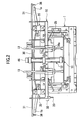
- FIG. 2 is a front view of the assembling jig and the radiator module;
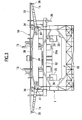
- FIG. 3 is a back view of the assembling jig and the radiator module;
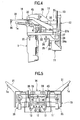
- FIG. 4 is a right side view of the assembling jig and the radiator module;
- FIG. 5 is a plane view of the assembling jig and the radiator module;
- FIG. 6 is a side view of the air balancer equipment;
- FIG. 7 is a side view of the essential part of the air balancer equipment;
- FIG. 8 is a block diagram of the control system for air balancer equipment and the assembling jig;
- FIG. 9 is a perspective view showing the situation where the assembling jig and the radiator module are moved to the vicinity of the front end part of the automobile body;
- FIG. 10 is a perspective view showing the situation where the assembling jig and the radiator module are moved to the assembling position;
- FIG. 11 is a perspective view showing the situation where the jig base of the assembling jig is positioned to the bumper reinforcement;
- FIG. 12 is a perspective view showing the situation where the radiator module is moved to the temporary assembling position by the assembling jig; and
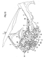
- FIG. 13 is a perspective view showing the situation where the radiator module is assembled to the assembling position by the assembling jig.
-
- Embodiments of the present invention will be explained hereinafter by referring to the drawings.
- FIGS. 1 to 5 are diagrams showing the situation where the radiator module is assembled to the radiator module assembling apparatus, FIGS. 6 to 8 are diagrams showing the air balancer equipment for the conveyor, FIGS. 9 to 13 are diagrams showing the situation where the radiator module assembling apparatus and the radiator module are supported by the air balancer equipment, and thus the radiator module is assembled to the front end part of the automobile body. In this connection, in the following explanation, the directions of frond, back, right and left denote corresponding directions with respect to the automobile body (see FIGS. 9 to 13).
-
Radiator module 1 is a module assembled from a radiator for an automobile, a condenser for an air conditioner and a radiator shroud, although the description for the radiator itself is omitted in theradiator module 1 shown in the drawing. Thisradiator module 1 is assembled in the vicinity of the back side ofbumper reinforcement 3, in the situation where thebumper reinforcement 3 has been assembled to the front end of the automobile to connect the front ends of the right and the left front side frames 2 to each other. - First, referring to FIGS. 1 to 5, the
radiator module apparatus 10 will be explained. This radiator module assembling apparatus 10 (hereinafter called "assembling jig") has, as major members, such asjig base member 11, cylinder for elevation (driving means for elevation) 12, a pair ofguide rods 13, elevatingbody 14, andhand body 16 supported byhorizontal spindle 15 directed to the car width direction. -
Jig base member 11 is bolted to hangingmember 56 connected toarm member 54 of outsideair balancer equipment 50 described afterward, and assemblingjig 10 andradiator module 1 set thereto are supported byair balancer equipment 50 and conveyed.Jig base member 11 hasbottom plate 21, right and left side plates, backplate 22, a pair ofbracket 23 at both sides of cylinder forelevation 12.Crosspiece 24 having square U-shaped cross-section is fixed at the top ofback plate 22, and a pair ofguide rods 13 are inserted into the guide holes of a pair ofguide pieces 24a formed such that they project to forward from crosspiece 24, thus the vicinity of the bottom end ofguide rod 13 is supported. - Referring FIG. 4, a pair of right and left
pin supporting plates 25 having L-shaped cross-section are fixed tocrosspiece 24, and to the pair ofpin supporting plates 25, positioning pins (third positioning member) 26, which are engagable to and disengagable from a pair of right and left positioning hole (not shown) ofbumper reinforcement 3 of the automobile from above, are fixed, respectively. The bottom ends of the pair ofguide rods 13 are welded tobottom plate 21 by way of cylinder body and supported by the pair ofguide pieces 24a. In addition, although not shown, the top ends of the pair ofguide rods 13 are connected to hangingmember 56. - Cylinder for
elevation 12 consisting of an air cylinder is disposed vertically with upside down to the center ofbottom plate 21 ofjig base member 11, and a piston rod extending downward fromcylinder body 12a is connected to the top surface ofbottom plate 21. - Elevating
body 14 hashorizontal member 27, a pair ofarm members 28 extending obliquely up behind fromhorizontal member 27, and a pair of the parts to be guided 29 which are provided in the vicinity of the lower end of the pair of arm members 28and externally engaged to the pair ofguide rods 13 slidably.Horizontal member 27 of elevatingbody 14 is connected to the midsection ofcylinder body 12a of cylinder forelevation 12 by way of a pair of connectingmembers 27a, and elevatingbody 14 goes up when the rod of cylinder forelevation 12 is extended and it goes down when the rod is pulled back. -
Hand body 16 serves for assemblingradiator module 1 by holding the module, and it is connected rotatably aroundspindle 15 directed to the car with direction to the top end of a pair ofarm members 28 of elevatingbody 14. -
Hand body 16 has such as holdingplate 30 corresponding to the top end ofradiator module 1, a pair of right and left projectingparts 31 extending obliquely and horizontally behind from both of the right and the left ends of holdingplate 30,shelf member 32 which extends right and left at front and below of holdingplate 30 and is fixed to holdingplate 30 by four connectingmembers 33, positioning pin (first positioning member) 34 which projects from the bottom surface of holdingplate 30 and is engagable to and disengagable from three positioning holes at the top end ofradiator module 1 from above, a pair ofpositioning pin mechanisms 35 provided at both right and left ends ofshelf member 32, a pair of positioning pins (fourth positioning member) 36 which project from the back ends of a pair of right and left projectingparts 31 and is engagable to and disengagable from a pair of positioning standard holes of a fender part 4 from above, and frame standard pin (frame standard member) 20 which projects from the bottom surface of the right end side ofshelf member 32. - Each of
positioning pin mechanisms 35 has such as a pair of upper and lower guide blocks 38 and cylinder for engage and disengage (driving means for engage and disengage) 37 disposed and fixed onshelf plate 32,pin holding plates radiator module 1 and are connected to the tip of the piston rod of cylinder for engage and disengage 37, positioning pin (second positioning member) 41 which project backward from the back side ofpin holding plates radiator module 1, and a pair ofguide rods 38a which are fixed to the top and the bottom ofpin holding plates positioning pin mechanisms 35, the cylinder body of cylinder for engage and disengage 37 and the pair of guide blocks 38 are fixed toshelf member 32. - When
radiator module 1 is positioned to and held byhand body 16,hand body 16 is moved downwardly from the upper position with respect toradiator module 1, threepositioning pins 34 at the lower part of holdingplate 30 are engaged to three positioning holes at the top end of theradiator module 1 from above respectively, then a pair ofpin holding plates positioning pin mechanisms 35, thus the pair of positioning pins 41 are horizontally engaged to a pair of positioning holes at the front end of theradiator module 1 from front. In this connection, those such as above-describedholding plate 30, threepositioning pins 34 and a pair ofpositioning pin mechanisms 35 correspond to the holding mechanism for holdingradiator module 1 with positioning it to handbody 16. - Explanation will be made for the structure for rotating
hand body 16 by connecting it to elevatingbody 14 rotatably. A pair of right and left connectingpieces 45 are fixed to holdingplate 30 ofhand body 16 in the vicinity of outside of a pair ofarm members 28 so that they project backward,spindle 15 is inserted through the back end of the pair ofarm members 28 and the front end of the pair of connectingpieces 45, and both ends of thespindle 15 are fixed to the pair of connectingpieces 45. By rotating thespindle 15, cylinder for rotation 46 (which consists of an air cylinder) as driving means for rotatinghand body 16 is obliquely disposed between holdingplate 30 and cylinder forelevation 12. - The end of the cylinder body of cylinder for
rotation 46 is rotatably connected to supportingmember 47 hooked to a pair ofarm member 28 by way of the projecting piece at the side of the end and a pin member and a pair of projecting pieces at the side of supportingmember 47. The tip ofpiston rod 46a of cylinder forrotation 46 is connected by pin to armmember 15a projecting fromspindle 15. In the situation wherehand body 16 is held in almost horizontal attitude as shown in FIG.1,piston rod 46a of cylinder forrotation 46 is extended, andradiator module 1 held byhand body 16 has almost vertical normal attitude (attitude for being assembled to the automobile body). Whenpiston rod 46a of cylinder forrotation 46 is pulled back,spindle 15 rotates so thathand body 16 has forward-inclining attitude, and thatradiator module 1 held byhand body 16 has forward-inclining attitude. - As described above, a pair of positioning pins (fourth positioning member) project from the bottom surface of the back ends of a pair of projecting
parts 31, and frame standard pin (frame standard member) 20, which is engagable to and disengagable from a positioning standard hole offront side frame 2 in the right side of the automobile body from above, projects downward from the bottom surface of the right end side ofshelf member 32. As a result, by engaging a pair of right and left positioning pins 36 ofhand body 16 to the positioning standard holes of right and left fender part 4 from above, and by engagingpositioning pin 20 ofshelf member 32 to the positioning standard hole offront side frame 2 in the right side from above,hand body 16 andradiator module 1 positioned to and held by thehand body 16 will be efficiently positioned to the automobile body with high precision. - Next, explanation for
air balancer equipment 50 will be made.Air balancer equipment 50 is an equipment for conveying assemblingjig 10 which holdsradiator module 1 to a mounting position at an automobile body and for holding assemblingjig 10 andradiator module 1 while they are assembled.Air balancer equipment 50 is an air balance equipment having an ordinal structure, and corresponds to the conveyor. - As shown in FIG. 6,
air balancer equipment 50 has such asbase body 51 as a base,column body 52 standing on thebase body 51,arm supporting member 53 connected and fixed to the top of thecolumn body 52,arm member 54 which contains two pairs of parallel link mechanisms connected to thearm supporting member 53, connectinghead member 55 at the tip of thearm member 54, and hangingmember 56 which is connected to the connectinghead member 55 and is extended to be bolted tojig base member 11 of assemblingjig 10. Provided at the vicinity of each of the four corners ofbase body 51 is outrigger 51a, and arm supportingmember 53 is rotatable horizontally in 180 degrees with respect tocolumn body 52. - Referring FIGS. 9 to 13, hanging
member 56 just described has nearly gate-shape, the center of the beam part at the upper end is bolted to connectinghead member 55, and the lower ends of a pair of gate-shape legs are bolted to a pair ofbracket 23 injig base member 11 of assemblingjig 10. In this connection, assemblingjig 10 is only schematically shown in FIG. 6. - As shown in FIG. 7, provided at
arm supporting member 53 ofair balancer equipment 50 arebody board 53a, air cylinder fordrive 57 standing upside down, and air pressure differential-type balancer 58 which controls supporting strength (the strength for supporting an object) for supporting at the tip ofarm member 54 by controlling the air pressure of air cylinder fordrive 57 throughcontrol valve 58a.Fulcrum connecting member 53b for connecting the fulcrum ofarm member 54 so that the position of the fulcrum is selected is provided at the lower part ofbody board 53a. Base terminalfulcrum guide part 53c for guiding the base terminal fulcrum ofarm member 54 to be connected topiston rod 57a of air cylinder fordrive 57 is provided at the upper part ofbody board 53, so that the base terminal fulcrum is guided by changing its position up and down.Balance weight 59 is provided at the base terminal of main arm 54a ofarm member 54. - Basically, the
air balancer equipment 50 controls the air pressure of cylinder fordrive 57 by air pressure differential-type balancer 58 in response to the angle or the attitude ofarm member 54 which changes according to the position of the object hung such as work. It also controls the amount of extension ofpiston rod 57a of air cylinder fordrive 57. Thus, it can support the whole weight of the object hung at the tip ofarm member 54, and control the supporting strength for hanging the object at the tip ofarm member 54 according to the command fromcontrol panel 61 described afterward. - Next, explanation will be made for a control system for the apparatus for assembling
radiator module 10 which contains a control system for theair balancer equipment 50. In this connection, a plurality of air hoses tocylinders jig 10 and plurality of leads to proximity switches (described afterward) 63, 64 provided on assemblingjig 10 are disposed alongarm member 54 ofair balancer equipment 50. The plurality of air hoses are connected to an air supply source, and the plurality of leads are connected to control unit (described afterward) 60. As shown in FIG. 8,control unit 60 having microcomputer, I/O and plurality of driving circuits is provided. To thecontrol unit 60,control panel 61,weight sensor 62 which can detect the weight of the object hung, and controlvalve 58a of differential pressure-type balancer 58 are connected. In addition, to controlunit 60, proximity switches (described afterward) 63, 64 provided on assemblingjig 10,solenoid valve 65 of an air circuit for cylinder forrotation 46, andsolenoid valve 66 of an air circuit for a pair of cylinder for engage and disengage 37are connected. - At the initial setup, if the weights of above-described
assembling jig 10 andradiator module 1 are detected byweight sensor 62 and are input to controlunit 60, and thus the total weight is set as the support strength for supporting byarm member 54, within the predetermined range of the movement ofarm member 54 ofair balancer equipment 50, the total weight of assemblingjig 10 andradiator module 1 will be supported and movable by pushing with hands. - Next, with referring FIG.1 and FIGS 9 to 13, explanation will be made for the method for assembling
radiator module 1 to the front end part of the automobile body by using above-describedair balancer equipment 50 and assemblingjig 10 which is supported by theair balancer equipment 50 and is conveyed to the position of the automobile body. - Before starting assembly, the weights of assembling
jig 10 andradiator module 1 supported thereby are detected byweight sensor 62 ofair balancer equipment 50 and are memorized bycontrol unit 60, and thus setup is made so that the total weight is hung and supported byarm member 54 ofair balancer equipment 50. - In the first step, the lower part of hanging
member 56 connected to the tip ofarm member 54 ofair balancer equipment 50 is bolted tojig base member 11 so that assemblingjig 10 andradiator module 1 can be hung thereby. After that, as shown in FIG. 1,radiator module 1 is positioned to and held byhand body 16. On this occasion,hand body 16 is kept in almost vertical as its normal attitude. Holdingplate 30 ofhand body 16 is faced to the upper part ofradiator module 1. Assemblingjig 10 is moved downwardly from above towardradiator module 1. Thus, threepositioning pins 34 provided on holdingplate 30 are engaged to three positioning holes at the upper end ofradiator module 1. - Then, the piston rod of cylinder for engage and disengage 37 of a pair of right and left
positioning pin mechanisms 35 is extended, and a pair of right and left positioning pins 41 are engaged to a pair of positioning holes at the front end ofradiator module 1. Next, in the second step, as shown in FIG. 1, assemblingjig 10 andradiator module 1 hung byarm member 54 of above-describedair balancer equipment 50 are moved to the vicinity of the front end of the automobile body by pushing with hands. - Then, in the third step, as shown in FIG. 9, by extending the piston rod of cylinder for
elevation 12, elevatingbody 14,hand body 16 andradiator module 1 are set to the elevated position with respect tojig base member 11. In addition, by pulling backpiston rod 46a of cylinder forrotation 46,hand body 16 andradiator module 1 are set to the forward-inclining attitude. Then, as shown in FIG. 10,arm member 54, assemblingjig 10 andradiator module 1 are moved to the front end part of the automobile body. After a pair of positioning pins 26 ofjig base member 11 are faced to a pair of positioning holes ofbumper reinforcement 3 from above, as shown in FIG. 11, assemblingjig 10 is moved downwardly, a pair of positioning pins 26 are engaged to a pair of positioning holes, andjig base member 11 is positioned to bumper reinforcement. - Then, in the fourth step, as shown in FIG. 12, by pulling back the piston rod of cylinder for
elevation 12, with keeping the forward-inclining attitude ofhand body 16 andradiator module 1, elevatingbody 14,hand body 16 andradiator module 1 are moved downwardly with respect tojig base member 11 to a predetermined non-interference down position, which enables them to avoid interfering with the automobile body (bumper reinforcement 3), and which is detected byproximity switch 63. Next, by extendingpiston rod 46a of cylinder forrotation 46,hand body 16 andradiator module 1 are set to their normal attitude. The reason whyradiator module 1 is moved downwardly with keeping its forward-inclining attitude is because the interference between the projecting part at the front side ofradiator module 1 andbumper reinforcement 3 should be avoided. - Next, as shown in FIG. 13,
hand body 16 andradiator module 1 are moved downwardly to a predetermined down end, which is detected byproximity switch 64. Positioning is made by engaging a pair of right and left positioning pins 36 at right and left projectingpart 31 ofhand body 16 to the positioning holes of right and left fender parts 4. At the same time, framestandard pin 20 provided onshelf member 32 is engaged to the positioning standard hole at front side frame of the right side. Thus, by three points consist of a pair of positioning pins 36 and framestandard pin 20, assemblingjig 10 is positioned to the automobile body with high precision. - Next, in the fifth step, by controlling
control panel 61, the supporting strength for supporting assemblingjig 10 andradiator module 1 byarm member 54 ofair balancer equipment 50 is reduced by a predetermined value (such as 5kgw (=c.a. 0.51N)). As a result, plurality of parts to be connected 1a, 1b ofradiator module 1 can intimately contact with plurality of parts for connection on the side of the automobile body. In this connection, the plurality of parts to be connected 1a, 1b are a pair of parts to be connected 1a at both right and left ends of shroud upper ofradiator module 1 and a pair of parts to be connected 1b at both right and left ends of the front end of radiator shroud which is connected to bracket for fixing shroud (connecting part) 2a provided at the front ends of right and left front side frames 2. - Next, in the sixth step, plurality of the parts to be connected 1a, 1b of
radiator module 1 is connected and fixed to bracket for fixingshroud 2a fixed to the connecting parts of right and left fender parts 4 and front side frame 4, respectively. - Next, in the seventh step, by pulling back the piston rod of cylinder for engage and disengage 37 of a pair of
positioning pin mechanisms 35, a pair of positioning pins 41 are disengaged fromradiator module 1. In addition, by extending the piston rod of cylinder forelevation 12 by a predetermined length, elevatingbody 14 andhand body 16 are elevated by around 5cm, and by disengaging threepositioning pins 34 fromradiator module 1,hand body 16 is separated fromradiator module 1. - Prior to the separation, by controlling
control panel 61, the supporting strength for supporting assemblingjig 10 byarm member 54 ofair balancer equipment 50 is reduced by a weight ofradiator module 1. Thus, whenhand body 16 is separated fromradiator module 1, assemblingjig 10 together witharm member 54 are prevented from jumping upward without fault. - Next, in the eighth step,
arm member 54 is manually moved to the original position of the conveyer, and the piston rod of cylinder forelevation 12 is pulled back and switched to the initial status, and thus they will be on stand by until next assembly ofradiator module 1. - According to the above-described apparatus and method for assembling
radiator module 1, the following results will be obtained. Since radiator module is assembled whilebumper reinforcement 3 is assembled to connect the front ends of the right and the left front side frames 2 of the automobile body to each other so that the structure of the front part of the automobile body is fixed, the radiator module will be assembled efficiently with high precision. In the third step, sincejig base member 11 is positioned tobumper reinforcement 3 by positioningpin 26,jig base member 11 will be positioned to the automobile body with high precision by usingbumper reinforcement 3 effectively. - In the fourth step, since elevating
body 14,hand body 16 andradiator module 1 are moved downwardly from the upper position with respect tojig base member 11, and a pair of the right and the left positioning pins 36 ofhand body 16 are positioned to right and left fender parts of the automobile body 4, respectively,hand body 16 will be positioned to fender part 4 with high precision. - In the first step, since
radiator module 1 is held byhand body 16 with high precision, by positioninghand body 16 precisely to fender part 4,radiator module 1 will be positioned precisely with respect to fender part 4 andfront side frame 2. - In the fourth step, with avoiding the interference between
radiator module 1 and the automobile body (bumper reinforcement 3),radiator module 1 will be positioned precisely to right and left fender parts 4. Owing to the pair of right and left positioning pins 36 ofhand body 16 and framestandard pin 20,hand body 16 is positioned to the automobile body by the three different points, and thus handbody 16 will be positioned to the automobile body with high precision. - In the fifth step, a pair of parts to be connected 1a, 1b at both right and left ends of shroud upper of
radiator module 1 are fixed to connecting parts of right and left fender parts 4 and to connectingbracket 2a at the vicinity of the front ends of front side frames 2, respectively. After that, in the seventh step, a pair of positioning pins 41 of a pair ofpositioning pin mechanisms 35 are disengaged from the positioning holes ofradiator module 1, and threepositioning pins 34 on holdingplate 30 ofhand body 16 are disengaged from the positioning holes ofradiator module 1, so thathand body 16 is separated fromradiator module 1. - In the fifth step, since the supporting strength for supporting assembling
jig 10 andradiator module 1 byarm member 50 ofair balancer equipment 50 is reduced, the positioning status of assemblingjig 10 andradiator module 1 with respect to the automobile body will be stabilized, and each of the plurality of parts to be connected 1a, 1b ofradiator module 1 will easily intimately contact, with the parts for connection on the side of the automobile body. - Since assembling
jig 10 andradiator module 1 are hung byair balancer equipment 50, if the supporting strength ofarm member 54 was not adjusted, and thus the weight ofradiator module 1 suddenly stopped acting onarm member 54 due to the release of the holding onhand body 16,arm member member 54 would abruptly jump. However, in the seventh step, by reducing the supporting strength for supporting assemblingjig 10 byarm member 54 by the weight of radiator module1, such abrupt jump ofarm member 54 will be avoided. In this connection, sinceradiator module 1 contains a condenser for an air conditioner in addition to the radiator, the condenser for an air conditioner will be assembled together with the radiator as a module. - In the above-described
assembling jig 10, by two pairs of positioning pins 34, 41 ofhand body 16 and a pair of cylinders for engage and disengage which engage and disengage a pair of positioning pins 41,radiator module 1 will be efficiently positioned to and held byhand body 16 with high precision. - In addition, by way of
positioning pin 26 ofjig base member 11,jig base member 11 will be efficiently positioned tobumper reinforcement 3 with high precision. Further,hand body 16 is positioned precisely to the automobile body by a pair of positioning pins 36 ofhand body 16 and framestandard pin 20, and thus in that situation,radiator module 1 will be efficiently assembled by way of assembling jig with high precision. - Here, explanation will be made for examples which alter the above-described embodiments partially.
- 1) Depending on the structure of
radiator module 1, whenradiator module 1 can be assembled to the automobile body by moving it downwardly from the upper position with keeping its vertical normal position, the mechanism for rotatinghand body 16 can be omitted in assemblingjig 10. - 2) The above-described frame
standard pin 20 can be constituted as a positioning pin of the type such that it is driven to be engaged or disengaged by an air cylinder. - 3) The driving means for elevation, driving means for rotation and driving means for engage and disengage are not limited to the above-described driving cylinder type, but can be motor driven-type driven by a motor.
-
- In this connection, it is possible to carry out the present invention in such an embodiment that above-described assembling jig is altered by adding thereto changes which are obvious for a person skilled in the art.
- According to the first embodiment of the present invention, since the radiator module is assembled while the bumper reinforcement is assembled to connect the front ends of the right and the left front side frames of the automobile body to each other so that the structure of the front part of the automobile body is fixed, the radiator module will be assembled efficiently with high precision. In the third step, since the jig base member is positioned to the bumper reinforcement by way of the positioning member, the jig base member will be positioned to the automobile body with high precision by using the bumper reinforcement effectively.
- In the fourth step, since the elevating body, hand body and radiator module are moved downwardly from the upper position with respect to jig base member, and a pair of the right and the left positioning members of the hand body are positioned to right and left fender parts of the automobile body, respectively, the hand body will be positioned to the fender part with high precision. Therefore, by holding the radiator module by the hand body with high precision, if the hand body is positioned precisely to fender part, the radiator module will be positioned precisely with respect to the fender part and the front side frame.
- According'to the second embodiment of the present invention, the hand body will be positioned precisely to the right and left fender parts with avoiding the interference between the radiator module and the automobile body.
- According to the third embodiment of the present invention, due to the right and the left positioning members and a positioning standard member of the hand body, the hand body is positioned to the automobile body by the three different points, and thus is positioned to the automobile body with high precision.
- According to the fourth embodiment of the present invention, each of the parts to be connected of the fender of the radiator module will be fixed to the parts for connection of right and left fender parts of the automobile body and to the part for connection at the vicinity of the front side frame, and then, the hand body will be separated from the radiator module by releasing the holding mechanism.
- According to the fifth embodiment of the present invention, by reducing supporting strength for supporting the assembling jig and the radiator module by an arm member of the conveyor, the positioning status of the assembling jig and the radiator module with respect to the automobile body will be stabilized, and the plurality of the parts to be connected of the radiator module will intimately contact with each of the parts for connection easily.
- When an air balancer equipment is employed as the conveyor, if the supporting strength of the arm member is not adjusted, and the weight of the radiator module suddenly stop acting on the arm member due to the release of the holding mechanism, the arm member can abruptly jump. According to the sixth embodiment of the present invention, such abrupt jump of the arm member will be avoided by reducing the supporting strength for supporting the assembling jig by an arm member by the weight of the radiator module.
- According to the seventh embodiment of the present invention, since the radiator module contains a condenser for an air conditioner in addition to the radiator, the condenser for an air conditioner will be assembled together with the radiator as a module.
- According to the eighth embodiment of the present invention, the apparatus for assembling a radiator module to the front end of an automobile body has such as a conveying means for carrying the assembly jig and the radiator module, the conveying means having an arm member; a jig base member which is connectable to the arm member; an elevating body which can be elevated on the jig base member by way of a guide rod, and driving means for elevating the elevating body; a hand body which is rotatable around an axis that is positioned in a widthwise direction of the automobile body on the elevating body, and driving means for rotating the hand body; a first positioning member which is provided on the hand body and is engagable to and disengagable from a positioning hole at the top end of the radiator module from above; a second positioning member which is provided on the hand body and is engagable to and disengagable from a positioning hole at the front end of the radiator module from front, and driving means for driving the second positioning member to engage and disengage the positioning hole; a third positioning member which is provided on the jig base member and is engagable to and disengagable from a positioning hole of a bumper reinforcement from above; and a fourth positioning member which is provided on the hand body and is engagable to and disengagable from a standard hole of a fender part from above, and a frame standard member which is engagable to and disengagable from a standard hole of a front side frame.
- As a result, the radiator module will be assembled on the hand body with high precision by way of the first and the second positioning members of the and body and driving means for driving the second positioning member to engage and disengage. In addition, the jig base member will be precisely positioned to the bumper reinforcement by way of the third positioning member of the jig base member. Furthermore, the hand body will be positioned to the fender part and the front side frame with high precision by way of the fourth positioning member and the frame standard member. Thus, the radiator module will be positioned precisely and effectively with respect to the automobile body.
Claims (8)
- A method for mounting a radiator module containing a radiator and a radiator shroud in the vicinity of the back side of a bumper reinforcement and assembling the radiator module to an automobile body while the bumper reinforcement is assembled to connect the front ends of the right and the left front side frames of the automobile body to each other, the method comprising the steps of:providing an assembling jig having a jig base member, an elevating body capable of being elevated with respect to the jig base member, a hand body connected to the elevating body, and a holding mechanism for holding the radiator module when positioning the radiator module on the hand body;connecting the jig base member to an arm member of an outside conveyor for carrying the assembly jig and the radiator module, and holding the radiator module on the hand body by way of the holding mechanism;moving the assembling jig and the radiator module to a position for subsequent mounting to the automobile body;positioning said jig base member next to the bumper reinforcement by way of the positioning member;moving the elevating body, the hand body and the radiator module downwardly from an upper position with respect to said jig base member; andpositioning a pair of the right and the left positioning members of the hand body to right and left fender parts of the automobile body, respectively.
- The method for assembling a radiator module for an automobile according to claim 1, wherein said hand body of the assembling jig is connected to the elevating body rotatably around an axis that is positioned in a widthwise direction of the automobile body, and in the step for moving the elevating body, the hand body and the radiator, the hand body and the radiator module are moved downwardly to a predetermined non-interference down position with keeping their forward-inclining attitude, then the hand body and the radiator module are set to their normal attitude, and they are moved downwardly to a predetermined down end and a pair of the right and the left positioning members of the hand body are positioned to right and left fender parts of the automobile body, respectively.
- The method for assembling a radiator module for an automobile according to claim 1 or 2, wherein in the step for positioning a pair of the right and the left positioning members of the hand body, a positioning standard member of the hand body is positioned to the front side frame.
- The method for assembling a radiator module for an automobile according to claim 1, 2 or 3, wherein the method comprising the steps of:fixing a plurality of parts of the radiator module to be connected to the parts for connection of right and left fender parts of the automobile body and to the part for connection at the vicinity of the front side frame, respectively; andseparating the hand body from the radiator module by releasing said holding mechanism.
- The method for assembling a radiator module for an automobile according to claim 1, 2, 3 or 4, wherein supporting strength for supporting the assembling jig and the radiator module by an arm member of the conveyor is reduced after the step for positioning a pair of the right and the left positioning members of the hand body and before the step for fixing a plurality of parts of the radiator module to be connected.
- The method for assembling a radiator module for an automobile according to one of the preceding claims , wherein, in said step for separating the hand body from the radiator module, the supporting strength for supporting the assembling jig by an arm member of the conveyor is reduced by the weight of the radiator module at the time of the release of the holding mechanism.
- The method for assembling a radiator module for an automobile according to one of the preceding claims, wherein said radiator module contains a condenser for an air conditioner in addition to the radiator.
- An apparatus for assembling a radiator module to the front end of an automobile body, the apparatus comprising:a conveying means for carrying the assembly jig and the radiator module, said conveying means having an arm member;a jig base member which is connectable to said arm member;an elevating body which can be elevated on the jig base member by way of a guide rod, and driving means for elevating the elevating body;a hand body which is rotatable around an axis that is positioned in a widthwise direction of the automobile body on said elevating body, and driving means for rotating the hand body;a first positioning member which is provided on said hand body and is engagable to and disengagable from a first positioning hole at the top end of the radiator module from above;a second positioning member which is provided on said hand body and is engagable to and disengagable from a second positioning hole at the front end of the radiator module from front, and driving means for driving the second positioning member to engage and disengage the second positioning hole;a third positioning member which is provided on said jig base member and is engagable to and disengagable from a third positioning hole of a bumper reinforcement from above; anda fourth positioning member which is provided on said hand body and is engagable to and disengagable from a first standard hole of a fender part from above, and a frame standard member which is engagable to and disengagable from a second standard hole of a front side frame.
Applications Claiming Priority (2)
| Application Number | Priority Date | Filing Date | Title |
|---|---|---|---|
| JP2002036486A JP3666658B2 (en) | 2002-02-14 | 2002-02-14 | Method and apparatus for assembling a radiator module for a vehicle |
| JP2002036486 | 2002-02-14 |
Publications (2)
| Publication Number | Publication Date |
|---|---|
| EP1336554A1 true EP1336554A1 (en) | 2003-08-20 |
| EP1336554B1 EP1336554B1 (en) | 2005-12-14 |
Family
ID=27621414
Family Applications (1)
| Application Number | Title | Priority Date | Filing Date |
|---|---|---|---|
| EP03002020A Expired - Lifetime EP1336554B1 (en) | 2002-02-14 | 2003-01-28 | Method and apparatus for assembling a radiator module for an automobile |
Country Status (6)
| Country | Link |
|---|---|
| US (1) | US7032283B2 (en) |
| EP (1) | EP1336554B1 (en) |
| JP (1) | JP3666658B2 (en) |
| KR (1) | KR20030068399A (en) |
| CN (1) | CN100406332C (en) |
| DE (1) | DE60302681T2 (en) |
Cited By (1)
| Publication number | Priority date | Publication date | Assignee | Title |
|---|---|---|---|---|
| FR2936771A1 (en) * | 2008-10-03 | 2010-04-09 | Renault Sas | ARRANGEMENT FOR THE MOUNTING OF A TECHNICAL FRONT OF A VEHICLE. |
Families Citing this family (20)
| Publication number | Priority date | Publication date | Assignee | Title |
|---|---|---|---|---|
| KR100428338B1 (en) * | 2001-10-16 | 2004-04-28 | 현대자동차주식회사 | Jig device for bolster assembly of vehicle |
| FR2899558B1 (en) * | 2006-04-06 | 2008-05-16 | Renault Sas | METHOD FOR ASSEMBLING A MOTOR VEHICLE WITH BASE ELEMENTS |
| KR100792891B1 (en) * | 2006-10-10 | 2008-01-08 | 현대자동차주식회사 | Jig device for assembly of multi-model front end modules |
| FR2914618B1 (en) * | 2007-04-03 | 2009-09-18 | Renault Sas | METHOD FOR MOUNTING A CROSS-SECTIONAL ELEMENT AND A TECHNICAL FRONT PANEL |
| KR101010670B1 (en) * | 2008-08-04 | 2011-01-24 | 형제테크(주) | Vehicle front end assembly inspection slot |
| KR101010669B1 (en) * | 2008-08-04 | 2011-01-24 | 형제테크(주) | Vehicle front carrier inspection slot |
| JP5257348B2 (en) * | 2009-12-08 | 2013-08-07 | 三菱自動車工業株式会社 | Body production equipment |
| US8910358B2 (en) | 2012-08-07 | 2014-12-16 | Sarah Piepenburg | Radiator repair jig |
| CN102962612B (en) * | 2012-11-22 | 2015-04-29 | 奇瑞汽车股份有限公司 | Inclinedly-pushing part arranging mechanism and part arranging method thereof |
| CN104759879B (en) * | 2015-02-06 | 2017-02-22 | 苏州鸿普精密模具有限公司 | Car condenser iron sleeve assembly machine operation method |
| CN105750908A (en) * | 2016-04-26 | 2016-07-13 | 黄石鑫华轮毂有限公司 | Automobile wheel hub die assembling and disassembling device |
| CN105817883B (en) * | 2016-06-08 | 2017-09-22 | 中国二十二冶集团有限公司 | Hydraulic press frame group is carried out to method using mold |
| JP6247723B1 (en) * | 2016-07-15 | 2017-12-13 | 本田技研工業株式会社 | Front end module mounting method and apparatus |
| CN108620787B (en) * | 2018-07-24 | 2023-12-01 | 嘉兴开天传动技术有限公司 | Rotatory radiator welding frock |
| CN108838675B (en) * | 2018-08-15 | 2023-11-03 | 嘉兴开天传动技术有限公司 | Assembling tool for radiator |
| JP7485522B2 (en) * | 2020-03-06 | 2024-05-16 | トヨタ自動車九州株式会社 | Car interior panel transport support device |
| CN113147805A (en) * | 2021-06-18 | 2021-07-23 | 兰普电器股份有限公司 | Modularization driver platform and module carrier |
| DE102021127846B3 (en) * | 2021-10-26 | 2022-11-24 | Dr. Ing. H.C. F. Porsche Aktiengesellschaft | Motor vehicle and method for mounting a housing on a bodyshell of a motor vehicle |
| KR20230089089A (en) * | 2021-12-13 | 2023-06-20 | 현대자동차주식회사 | Automatic mount system of front end module for vehicle |
| CN116728072B (en) * | 2023-06-15 | 2025-08-12 | 江苏克伦伯格热能技术有限公司 | Assembling jig and assembling method for main piece of indoor heating radiator |
Citations (4)
| Publication number | Priority date | Publication date | Assignee | Title |
|---|---|---|---|---|
| EP0477702A1 (en) * | 1990-09-28 | 1992-04-01 | Mazda Motor Corporation | Method for assembling a car |
| JPH0769244A (en) | 1993-09-02 | 1995-03-14 | Nissan Motor Co Ltd | Assembly method of front part of vehicle body and assembly jig used for the assembly method |
| JP2001030133A (en) | 1999-07-16 | 2001-02-06 | Nissan Motor Co Ltd | Work positioning device |
| US20020043820A1 (en) * | 2000-09-13 | 2002-04-18 | Sebastien Brogly | Vehicle subassembly including a cooling cassette and a support frame |
Family Cites Families (18)
| Publication number | Priority date | Publication date | Assignee | Title |
|---|---|---|---|---|
| US2428958A (en) * | 1944-07-25 | 1947-10-14 | Western Electric Co | Assembling apparatus |
| US3149825A (en) * | 1962-12-10 | 1964-09-22 | Ray V Watkins | Radiator repair device |
| JPS6062429A (en) * | 1983-09-13 | 1985-04-10 | Nissan Motor Co Ltd | Method and device for assembling parts |
| US5174004A (en) * | 1988-01-05 | 1992-12-29 | King & Sons Pty. Ltd. | Radiator clamping jig |
| JP2933702B2 (en) * | 1989-12-21 | 1999-08-16 | マツダ株式会社 | Vehicle front body structure and method of assembling the same |
| US5634746A (en) * | 1992-09-21 | 1997-06-03 | The Boeing Co. | Normality control for a tool nose |
| DE4438214A1 (en) * | 1994-10-26 | 1996-05-02 | Norbert Basler | Method of manufacturing a motor vehicle |
| US6205638B1 (en) * | 1997-10-24 | 2001-03-27 | Decoma International Inc. | End module assembly for installation on a vehicle and method for making the same |
| US6282769B1 (en) * | 1998-07-15 | 2001-09-04 | Cosma International Inc. | Motor vehicle end module assembly |
| US6170141B1 (en) * | 1998-09-25 | 2001-01-09 | Stanley Aviation Corporation | Shipping system for jet aircraft engine and method of installing and removing jet aircraft engine |
| US6578247B2 (en) * | 2000-08-31 | 2003-06-17 | International Truck Intellectual Property Company, Llc | Vehicle chassis inverter |
| AUPR000400A0 (en) * | 2000-09-08 | 2000-10-05 | Justoy Pty Ltd | Device and method for removal/installation of a vehicular component |
| US6629354B1 (en) * | 2000-11-13 | 2003-10-07 | Utica Enterprises, Inc. | Apparatus for immobilizing a frame structure in its free state to establish a net datum position thereof |
| JP3962552B2 (en) * | 2001-03-12 | 2007-08-22 | 日産自動車株式会社 | Car body transfer device |
| JP3765254B2 (en) * | 2001-07-25 | 2006-04-12 | 日産自動車株式会社 | Front end module assembly method and front end module assembly apparatus |
| KR100428338B1 (en) * | 2001-10-16 | 2004-04-28 | 현대자동차주식회사 | Jig device for bolster assembly of vehicle |
| US6682061B2 (en) * | 2002-01-14 | 2004-01-27 | Johnson Controls Technology Company | Actuator system for positioning a workpiece |
| US6785944B1 (en) * | 2002-03-04 | 2004-09-07 | Volvo Penta Of The Americas | Engine installation jig |
-
2002
- 2002-02-14 JP JP2002036486A patent/JP3666658B2/en not_active Expired - Fee Related
-
2003
- 2003-01-25 KR KR10-2003-0004994A patent/KR20030068399A/en not_active Withdrawn
- 2003-01-28 EP EP03002020A patent/EP1336554B1/en not_active Expired - Lifetime
- 2003-01-28 DE DE60302681T patent/DE60302681T2/en not_active Expired - Lifetime
- 2003-01-31 US US10/355,067 patent/US7032283B2/en not_active Expired - Lifetime
- 2003-01-31 CN CNB031206670A patent/CN100406332C/en not_active Expired - Fee Related
Patent Citations (4)
| Publication number | Priority date | Publication date | Assignee | Title |
|---|---|---|---|---|
| EP0477702A1 (en) * | 1990-09-28 | 1992-04-01 | Mazda Motor Corporation | Method for assembling a car |
| JPH0769244A (en) | 1993-09-02 | 1995-03-14 | Nissan Motor Co Ltd | Assembly method of front part of vehicle body and assembly jig used for the assembly method |
| JP2001030133A (en) | 1999-07-16 | 2001-02-06 | Nissan Motor Co Ltd | Work positioning device |
| US20020043820A1 (en) * | 2000-09-13 | 2002-04-18 | Sebastien Brogly | Vehicle subassembly including a cooling cassette and a support frame |
Non-Patent Citations (1)
| Title |
|---|
| PATENT ABSTRACTS OF JAPAN vol. 1995, no. 06 31 July 1995 (1995-07-31) * |
Cited By (3)
| Publication number | Priority date | Publication date | Assignee | Title |
|---|---|---|---|---|
| FR2936771A1 (en) * | 2008-10-03 | 2010-04-09 | Renault Sas | ARRANGEMENT FOR THE MOUNTING OF A TECHNICAL FRONT OF A VEHICLE. |
| WO2010037981A3 (en) * | 2008-10-03 | 2010-05-27 | Renault S.A.S. | Arrangement for mounting the front technical surface of a vehicle |
| US8813340B2 (en) | 2008-10-03 | 2014-08-26 | Renault S.A.S. | Arrangement for mounting the front technical surface of a vehicle |
Also Published As
| Publication number | Publication date |
|---|---|
| JP3666658B2 (en) | 2005-06-29 |
| US7032283B2 (en) | 2006-04-25 |
| DE60302681T2 (en) | 2006-08-31 |
| US20030150094A1 (en) | 2003-08-14 |
| KR20030068399A (en) | 2003-08-21 |
| EP1336554B1 (en) | 2005-12-14 |
| CN100406332C (en) | 2008-07-30 |
| DE60302681D1 (en) | 2006-01-19 |
| JP2003237652A (en) | 2003-08-27 |
| CN1438147A (en) | 2003-08-27 |
Similar Documents
| Publication | Publication Date | Title |
|---|---|---|
| EP1336554B1 (en) | Method and apparatus for assembling a radiator module for an automobile | |
| CN101172324A (en) | Systems and methods for assembling motor vehicle body structures or subassemblies thereof | |
| US20180015973A1 (en) | Method and apparatus for mounting front end module | |
| KR101550611B1 (en) | Door hinge loading device for vehicle | |
| KR101220105B1 (en) | Apparatus for transferring parts of vehicle | |
| JP2009113186A (en) | Screw tightening device | |
| CN106826882A (en) | Air-actuated turnover lifting device | |
| CN111844129B (en) | Robot maintenance device and robot maintenance method | |
| JP5421172B2 (en) | Welding line | |
| KR100893605B1 (en) | Inside main buck process | |
| KR101360045B1 (en) | Side panel align device of system for assembling body | |
| KR102573096B1 (en) | Glass mounting apparatus | |
| KR100666248B1 (en) | Shuttleline system of the vehicle body | |
| JPS6353074B2 (en) | ||
| JP2001047338A (en) | Product assembly method and product assembly device | |
| JP3059884B2 (en) | Mounting device for long heavy objects | |
| JPH07164187A (en) | Composite welding jig and welding method using the same | |
| KR100242188B1 (en) | High speed duct transfer conveyor system | |
| JP2993311B2 (en) | Welding equipment | |
| JP2004203106A (en) | Vehicle body front module positioning mounting device and method of mounting the same | |
| CN112108795B (en) | Positioning upright post sliding device and system | |
| CN110817734A (en) | Jacking device and intelligent delivery robot | |
| JP2685188B2 (en) | Conveyor device for vehicle assembly line | |
| JP3424195B2 (en) | Impact bar set equipment for automobile door production line | |
| KR20100041118A (en) | Teaching apparatus of transfer robot and control method thereof |
Legal Events
| Date | Code | Title | Description |
|---|---|---|---|
| PUAI | Public reference made under article 153(3) epc to a published international application that has entered the european phase |
Free format text: ORIGINAL CODE: 0009012 |
|
| AK | Designated contracting states |
Designated state(s): AT BE BG CH CY CZ DE DK EE ES FI FR GB GR HU IE IT LI LU MC NL PT SE SI SK TR |
|
| AX | Request for extension of the european patent |
Extension state: AL LT LV MK RO |
|
| 17P | Request for examination filed |
Effective date: 20040108 |
|
| AKX | Designation fees paid |
Designated state(s): DE |
|
| 17Q | First examination report despatched |
Effective date: 20041117 |
|
| GRAP | Despatch of communication of intention to grant a patent |
Free format text: ORIGINAL CODE: EPIDOSNIGR1 |
|
| GRAS | Grant fee paid |
Free format text: ORIGINAL CODE: EPIDOSNIGR3 |
|
| GRAA | (expected) grant |
Free format text: ORIGINAL CODE: 0009210 |
|
| AK | Designated contracting states |
Kind code of ref document: B1 Designated state(s): DE |
|
| REF | Corresponds to: |
Ref document number: 60302681 Country of ref document: DE Date of ref document: 20060119 Kind code of ref document: P |
|
| PLBE | No opposition filed within time limit |
Free format text: ORIGINAL CODE: 0009261 |
|
| STAA | Information on the status of an ep patent application or granted ep patent |
Free format text: STATUS: NO OPPOSITION FILED WITHIN TIME LIMIT |
|
| 26N | No opposition filed |
Effective date: 20060915 |
|
| PGFP | Annual fee paid to national office [announced via postgrant information from national office to epo] |
Ref country code: DE Payment date: 20180117 Year of fee payment: 16 |
|
| REG | Reference to a national code |
Ref country code: DE Ref legal event code: R119 Ref document number: 60302681 Country of ref document: DE |
|
| PG25 | Lapsed in a contracting state [announced via postgrant information from national office to epo] |
Ref country code: DE Free format text: LAPSE BECAUSE OF NON-PAYMENT OF DUE FEES Effective date: 20190801 |