EP1336040B1 - Verfahren zum einspritzen von kraftstoff während der startphase einer brennkraftmaschine - Google Patents
Verfahren zum einspritzen von kraftstoff während der startphase einer brennkraftmaschine Download PDFInfo
- Publication number
- EP1336040B1 EP1336040B1 EP01996678A EP01996678A EP1336040B1 EP 1336040 B1 EP1336040 B1 EP 1336040B1 EP 01996678 A EP01996678 A EP 01996678A EP 01996678 A EP01996678 A EP 01996678A EP 1336040 B1 EP1336040 B1 EP 1336040B1
- Authority
- EP
- European Patent Office
- Prior art keywords
- crankshaft
- cylinder
- internal combustion
- combustion engine
- injection
- Prior art date
- Legal status (The legal status is an assumption and is not a legal conclusion. Google has not performed a legal analysis and makes no representation as to the accuracy of the status listed.)
- Expired - Lifetime
Links
- 238000002485 combustion reaction Methods 0.000 title claims description 28
- 238000000034 method Methods 0.000 title claims description 25
- 239000000446 fuel Substances 0.000 title claims description 12
- 238000002347 injection Methods 0.000 claims description 30
- 239000007924 injection Substances 0.000 claims description 30
- 238000000926 separation method Methods 0.000 claims 2
- 230000000737 periodic effect Effects 0.000 claims 1
- 239000007858 starting material Substances 0.000 description 6
- 239000003344 environmental pollutant Substances 0.000 description 4
- 231100000719 pollutant Toxicity 0.000 description 4
- 230000003111 delayed effect Effects 0.000 description 2
- 238000001514 detection method Methods 0.000 description 2
- 238000010586 diagram Methods 0.000 description 2
- 239000000203 mixture Substances 0.000 description 2
- 235000000621 Bidens tripartita Nutrition 0.000 description 1
- 240000004082 Bidens tripartita Species 0.000 description 1
- 230000033228 biological regulation Effects 0.000 description 1
- 230000007423 decrease Effects 0.000 description 1
- 208000006637 fused teeth Diseases 0.000 description 1
- 230000001360 synchronised effect Effects 0.000 description 1
Images

Classifications
-
- F—MECHANICAL ENGINEERING; LIGHTING; HEATING; WEAPONS; BLASTING
- F02—COMBUSTION ENGINES; HOT-GAS OR COMBUSTION-PRODUCT ENGINE PLANTS
- F02D—CONTROLLING COMBUSTION ENGINES
- F02D41/00—Electrical control of supply of combustible mixture or its constituents
- F02D41/009—Electrical control of supply of combustible mixture or its constituents using means for generating position or synchronisation signals
-
- F—MECHANICAL ENGINEERING; LIGHTING; HEATING; WEAPONS; BLASTING
- F02—COMBUSTION ENGINES; HOT-GAS OR COMBUSTION-PRODUCT ENGINE PLANTS
- F02D—CONTROLLING COMBUSTION ENGINES
- F02D41/00—Electrical control of supply of combustible mixture or its constituents
- F02D41/02—Circuit arrangements for generating control signals
- F02D41/04—Introducing corrections for particular operating conditions
- F02D41/047—Taking into account fuel evaporation or wall wetting
-
- F—MECHANICAL ENGINEERING; LIGHTING; HEATING; WEAPONS; BLASTING
- F02—COMBUSTION ENGINES; HOT-GAS OR COMBUSTION-PRODUCT ENGINE PLANTS
- F02D—CONTROLLING COMBUSTION ENGINES
- F02D41/00—Electrical control of supply of combustible mixture or its constituents
- F02D41/02—Circuit arrangements for generating control signals
- F02D41/04—Introducing corrections for particular operating conditions
- F02D41/06—Introducing corrections for particular operating conditions for engine starting or warming up
- F02D41/062—Introducing corrections for particular operating conditions for engine starting or warming up for starting
-
- F—MECHANICAL ENGINEERING; LIGHTING; HEATING; WEAPONS; BLASTING
- F02—COMBUSTION ENGINES; HOT-GAS OR COMBUSTION-PRODUCT ENGINE PLANTS
- F02D—CONTROLLING COMBUSTION ENGINES
- F02D41/00—Electrical control of supply of combustible mixture or its constituents
- F02D41/02—Circuit arrangements for generating control signals
- F02D41/04—Introducing corrections for particular operating conditions
- F02D41/042—Introducing corrections for particular operating conditions for stopping the engine
Definitions
- the present invention relates to a method of injection of fuel in a multi-cylinder internal combustion engine.
- the present invention is based on the object Method of injecting fuel into a multi-cylinder Specify internal combustion engine, which is an emission-optimized Quick start of the engine allows.
- the present invention is based on the finding that a Internal combustion engine after switching off in disengaged Condition always at certain discrete positions remains, with the number of discrete positions over two Crankshaft revolutions (760 °) always the number of cylinders equivalent. Thus, in the case of n cylinders, these are n stop angle positions.
- n stoppage angle positions initially unknown When the internal combustion engine starts, these are n stoppage angle positions initially unknown. With the help of the camshaft signal However, the number of unknown stall angle positions can be reduced to n / 2. Thus, can in the inventive method depending on the Camshaft signal and the stored stationary angle positions a cylinder to be selected first is supplied with a pre-injection, while the rest Pre-injection will be discontinued later. In contrast to the above-described prior art method thus become the first cylinders not at the same time, but always in time offset from each other supplied with the pre-injectors.
- the one subdivision of each working game into two segments corresponding to two consecutive crankshaft revolutions allows the standstill angle positions in two groups subdivided, and it is determined that group, which the current stall angle position at which the Internal combustion engine has stopped.
- group which the current stall angle position at which the Internal combustion engine has stopped.
- the inventive method ensures that all pre-injectors are actually involved in the incineration participate, so that the pollutant emissions, in particular the HC emissions to the level of a sequential start decline. Nevertheless, early fuel injection is possible so that the inventive method a faster Start compared to a sequential starting method allows.
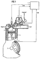
- FIG. 1 shows a schematic partial section through a Internal combustion engine, which in the described embodiment for illustrative purposes as a four-cylinder gasoline engine is formed with gasoline injection.
- the internal combustion engine 3 is a central one in the usual way electronic control unit 1 associated with the ignition, Fuel injection and other processes of the internal combustion engine controls.
- Each cylinder 7 is at least one inlet valve 6 and at least one injection valve 2 assigned.
- the Injector 2 injects fuel into the intake manifold immediately before or on the valve disk of the intake valve 6 from.
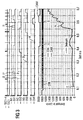
- the crankshaft 8 is a crankshaft sensor 4 with a toothed Encoder wheel assigned to the crankshaft angle representative crankshaft signal CRK (see lower half of Figures 2 and 3) generated.
- the camshaft 5 can be connected to the crankshaft 8 rotatably connected or angle adjustable relative to it be.
- crankshaft signal CRK corresponds to a tooth of the sender wheel, wherein a double tooth gap after every 60 teeth as a synchronization pulse S for each one full turn of the crankshaft 8 serves.
- the cam signal CAM has two different ones Level, the two consecutive revolutions associated with the crankshaft.
- the camshaft signal CAM and the crankshaft signal CRK with its synchronization pulses S allow an unambiguous assignment of the crankshaft position in the working game.
- the camshaft signal may also have other pulse and level shapes exhibit; However, it should be ensured that the Camshaft signal a subdivision of each working cycle in two segments (ä 360 °) corresponding to two consecutive Crankshaft revolutions (720 °) allowed.
- the speed N the internal combustion engine plotted over time In the lower half of Figure 2 are in addition to the crankshaft signal CRK and the cam signal CAM, the speed N the internal combustion engine plotted over time.
- the drive signals IV1 - IV4 for the four injectors over time where the four pre-injectors I with I1 - I4 are designated.
- the drive signals EV1 - EV4 are for the four Intake valves plotted against time, with the opening pulses for the opening of the inlet valves with E1 - E4 are.
- the top two lines 2 shows the pulses for the top dead center (TDC1 - TDC4) the four cylinders or top dead center (TDC1) of the cylinder 1 shown.
- Starter ID E only one cylinder, its inlet valve closed with security or mostly closed, supplied with the pilot injector .; in the example of Figure 2 this is the cylinder 4 with the pilot injector I4.
- the pre-injection I3 ' is opposed, as by a dotted line P indicated, not delivered at this time.
- the diagram of Figure 3 corresponds to that of Figure 2, except of that at the time of the starter E the camshaft signal CAM is high and the internal combustion engine 50 ( ⁇ 7) teeth of the crankshaft sensor before the first Synchronization pulse S has stopped. Since at the time the start detection E the camshaft signal CAM high is the first cylinder group of the cylinders 1, 2 and the second cylinder group formed by the cylinders 3, 4. In this case, (after eight recognized and valid Teeth of the crankshaft sensor) only the cylinder 2 with the Vorabspritzer supplied I2, while in the previously known Provided method pre-injector I1 'for the cylinder first is omitted. Since in this example 28 teeth after the Starter ID E has not yet occurred a synchronization pulse S.
- the next or the next pre-injection is, the next or the next pre-injection at a predetermined angular distance to the angular position, on delivered the first pre-injection.
- the first synchronization pulse S can restore the order of the following pre-injectors from the central control unit 1 in the sequential injection mode be determined.
Landscapes
- Engineering & Computer Science (AREA)
- Chemical & Material Sciences (AREA)
- Combustion & Propulsion (AREA)
- Mechanical Engineering (AREA)
- General Engineering & Computer Science (AREA)
- Electrical Control Of Air Or Fuel Supplied To Internal-Combustion Engine (AREA)
- Combined Controls Of Internal Combustion Engines (AREA)
Description
Claims (6)
- Verfahren zum Einspritzen von Kraftstoff in eine mehrzylindrige Brennkraftmaschine mit
mindestens einem Einspritzventil (2) je Zylinder (7),
einer Nockenwelle (5) zur Betätigung der Einlassventile (6), die mit der halben Drehzahl der Kurbelwelle (8) umläuft,
einem Nockenwellensensor (9), der ein periodisches Nockenwellensignal (CAM) liefert,
einem Kurbelwellensensor (4), der ein den Kurbelwellenwinkel darstellendes Kurbelwellensignal (CRK) mit einem Synchronisationsimpuls (S) je Kurbelwellenumdrehung liefert, und
einem zentralen Steuergerät (1), das die Einspritzventile (2) so steuert, dass sie während einer Startphase je einen Kraftstoff-Vorabeinspritzer (I) pro Zylinder (7) und anschließend von dem Steuergerät (1) ermittelte Kraftstoffmengen im normalen sequentiellen Einspritzbetrieb einspritzen,
dadurch gekennzeichnet, dass in dem zentralen Steuergerät (1) eine der Zylinderanzahl entsprechende Anzahl Stillstands-Winkelpositionen der Kurbelwelle (8), an denen die Brennkraftmaschine (3) nach Abschalten im ausgekuppelten Zustand stehen bleiben kann, gespeichert werden,
und dass während der Startphase die Zylinder (7) in Abhängigkeit von dem Nockenwellensignal (CAM) und den gespeicherten Stillstands-Winkelpositionen zeitlich nacheinander mit den Vorabeinspritzern (I) versorgt werden. - Verfahren nach Anspruch 1, dadurch gekennzeichnet, dass das Nockenwellensignal (CAM) eine Unterteilung jedes Arbeitsspiels in zwei Segmente (360°) entsprechend zwei aufeinanderfolgenden Kurbelwellenumdrehungen (720°) erlaubt und dass in Abhängigkeit von dem Nockenwellensignal (CAM) die Stillstands-Winkelpositionen in zwei Gruppen unterteilt werden und diejenige Gruppe ermittelt wird, welche die aktuelle Stillstands-Winkelposition beinhaltet, an der die Brennkraftmaschine stehengeblieben ist.
- Verfahren nach Anspruch 2, dadurch gekennzeichnet, dass in Abhängigkeit von dem Nockenwellensignal (CAM) die Zylinder in eine erste und zweite Gruppe unterteilt werden und dass aus der ersten Zylindergruppe in Abhängigkeit von der ermittelten Gruppe der Stillstands-Winkelpositionen ein Zylinder ausgewählt wird, der als erster mit einem Vorabeinspritzer (I) versorgt wird.
- Verfahren nach Anspruch 3, dadurch gekennzeichnet, dass derjenige Zylinder der ersten Zylindergruppe, dessen Einlassventil mit Sicherheit geschlossen oder zumindest überwiegend geschlossen ist, als erster mit einem Vorabeinspritzer versorgt wird.
- Verfahren nach Anspruch 4, dadurch gekennzeichnet, dass der Winkelabstand zwischen der Kurbelwellen-Winkelposition, an der der erste Vorabeinspritzer (I) abgegeben wird, und der Winkelposition des ersten Synchronisationsimpulses (S) mit dem Winkelabstand zwischen zwei benachbarten gespeicherten Stillstands-Winkelpositionen verglichen wird und in Abhängigkeit von diesem Vergleich die Reihenfolge der nächsten Vorabeinspritzer (I) bestimmt wird.
- Verfahren nach einem der vorhergehenden Ansprüche, dadurch gekennzeichnet, dass nach Auftreten des ersten Synchronisationsimpulses (S) die Reihenfolge der verbleibenden Vorabeinspritzer (I) im sequentiellen Betrieb bestimmt wird.
Applications Claiming Priority (3)
| Application Number | Priority Date | Filing Date | Title |
|---|---|---|---|
| DE10056862 | 2000-11-16 | ||
| DE10056862A DE10056862C1 (de) | 2000-11-16 | 2000-11-16 | Verfahren zum Einspritzen von Kraftstoff während der Startphase einer Brennkraftmaschine |
| PCT/DE2001/004313 WO2002040847A2 (de) | 2000-11-16 | 2001-11-15 | Verfahren zum einspritzen von kraftstoff während der startphase einer brennkraftmaschine |
Publications (2)
| Publication Number | Publication Date |
|---|---|
| EP1336040A2 EP1336040A2 (de) | 2003-08-20 |
| EP1336040B1 true EP1336040B1 (de) | 2005-08-03 |
Family
ID=7663546
Family Applications (1)
| Application Number | Title | Priority Date | Filing Date |
|---|---|---|---|
| EP01996678A Expired - Lifetime EP1336040B1 (de) | 2000-11-16 | 2001-11-15 | Verfahren zum einspritzen von kraftstoff während der startphase einer brennkraftmaschine |
Country Status (4)
| Country | Link |
|---|---|
| US (1) | US6880531B2 (de) |
| EP (1) | EP1336040B1 (de) |
| DE (2) | DE10056862C1 (de) |
| WO (1) | WO2002040847A2 (de) |
Families Citing this family (16)
| Publication number | Priority date | Publication date | Assignee | Title |
|---|---|---|---|---|
| DE10221393B4 (de) * | 2002-05-14 | 2005-12-22 | Siemens Ag | Vorrichtung und Verfahren zum Starten einer mehrzylindrigen Brennkraftmaschine |
| DE10228147B3 (de) * | 2002-06-24 | 2004-01-22 | Siemens Ag | Verfahren zum Bestimmen der Start-Winkelposition einer Brennkraftmaschine |
| US6931840B2 (en) * | 2003-02-26 | 2005-08-23 | Ford Global Technologies, Llc | Cylinder event based fuel control |
| US8100822B2 (en) * | 2004-03-16 | 2012-01-24 | Macroplata Systems, Llc | Anoscope for treating hemorrhoids without the trauma of cutting or the use of an endoscope |
| US7415348B1 (en) * | 2007-02-20 | 2008-08-19 | Gm Global Technology Operations, Inc. | Multiple injection blend for direct injected engines |
| GB2461552A (en) * | 2008-07-03 | 2010-01-06 | Gm Global Tech Operations Inc | Method of starting an internal combustion engine |
| DE102010028167A1 (de) * | 2010-04-23 | 2011-10-27 | W.O.M. World Of Medicine Ag | Invasives Instrument zur Bearbeitung von Gefäßen und ein Verfahren |
| DE102010027213A1 (de) | 2010-07-15 | 2012-01-19 | Continental Automotive Gmbh | Verfahren und Steuergerät zum Steuern einer Brennkraftmaschine |
| DE102010027215B4 (de) | 2010-07-15 | 2013-09-05 | Continental Automotive Gmbh | Verfahren und Steuergerät zum Steuern einer Brennkraftmaschine |
| DE102010027214B4 (de) | 2010-07-15 | 2013-09-05 | Continental Automotive Gmbh | Verfahren und Steuergerät zum Steuern einer Brennkraftmaschine |
| US11162444B2 (en) * | 2019-02-08 | 2021-11-02 | Honda Motor Co., Ltd. | Systems and methods for a crank sensor having multiple sensors and a magnetic element |
| US11199426B2 (en) * | 2019-02-08 | 2021-12-14 | Honda Motor Co., Ltd. | Systems and methods for crankshaft tooth encoding |
| US11131567B2 (en) | 2019-02-08 | 2021-09-28 | Honda Motor Co., Ltd. | Systems and methods for error detection in crankshaft tooth encoding |
| US11181016B2 (en) | 2019-02-08 | 2021-11-23 | Honda Motor Co., Ltd. | Systems and methods for a crank sensor having multiple sensors and a magnetic element |
| US11959820B2 (en) | 2021-03-17 | 2024-04-16 | Honda Motor Co., Ltd. | Pulser plate balancing |
| CN112983666B (zh) * | 2021-03-26 | 2022-09-13 | 中国第一汽车股份有限公司 | 汽车快速启动方法、装置、设备及存储介质 |
Family Cites Families (9)
| Publication number | Priority date | Publication date | Assignee | Title |
|---|---|---|---|---|
| JPS6069247A (ja) | 1983-09-27 | 1985-04-19 | Nissan Motor Co Ltd | 内燃機関の燃料噴射制御装置 |
| ES2024616B3 (es) * | 1988-11-28 | 1992-03-01 | Siemens Ag | Procedimiento para inyectar combustible en una maquina de combustion interna |
| JPH03260344A (ja) * | 1990-03-08 | 1991-11-20 | Honda Motor Co Ltd | 内燃エンジンの制御方法 |
| US5165373A (en) * | 1991-05-24 | 1992-11-24 | Cheng Dah Y | Electro-thermal pulsed fuel injector and system |
| DE4304163A1 (de) * | 1993-02-12 | 1994-08-25 | Bosch Gmbh Robert | Einrichtung zur Steuerung der Kraftstoffeinspritzung bei einer Brennkraftmaschine |
| US5450829A (en) * | 1994-05-03 | 1995-09-19 | Servojet Products International | Electronically controlled pilot fuel injection of compression ignition engines |
| DE19741966C2 (de) * | 1997-09-23 | 2002-11-07 | Siemens Ag | Verfahren zum Einspritzen von Kraftstoff bei einer Mehrzylinderbrennkraftmaschine |
| US6032640A (en) * | 1998-10-02 | 2000-03-07 | The University Of British Columbia | Control method for spark-ignition engines |
| US6612292B2 (en) * | 2001-01-09 | 2003-09-02 | Nissan Motor Co., Ltd. | Fuel injection control for diesel engine |
-
2000
- 2000-11-16 DE DE10056862A patent/DE10056862C1/de not_active Expired - Fee Related
-
2001
- 2001-11-15 DE DE50106997T patent/DE50106997D1/de not_active Expired - Lifetime
- 2001-11-15 EP EP01996678A patent/EP1336040B1/de not_active Expired - Lifetime
- 2001-11-15 US US10/432,139 patent/US6880531B2/en not_active Expired - Lifetime
- 2001-11-15 WO PCT/DE2001/004313 patent/WO2002040847A2/de not_active Ceased
Also Published As
| Publication number | Publication date |
|---|---|
| DE10056862C1 (de) | 2002-05-08 |
| US6880531B2 (en) | 2005-04-19 |
| WO2002040847A2 (de) | 2002-05-23 |
| US20040020472A1 (en) | 2004-02-05 |
| WO2002040847A3 (de) | 2003-02-20 |
| DE50106997D1 (de) | 2005-09-08 |
| EP1336040A2 (de) | 2003-08-20 |
Similar Documents
| Publication | Publication Date | Title |
|---|---|---|
| EP1336040B1 (de) | Verfahren zum einspritzen von kraftstoff während der startphase einer brennkraftmaschine | |
| EP0371158B1 (de) | Verfahren zum Einspritzen von Kraftstoff in eine Brennkraftmaschine | |
| EP1301706B1 (de) | Verfahren zum starten einer mehrzylindrigen brennkraftmaschine | |
| EP0640762B1 (de) | Zylinder Synchronisation einer Mehrzylinder Brennkraftmaschine durch Detektion eines gezielten Verbrennungsaussetzers | |
| DE19748018C2 (de) | Kraftstoff-Direkteinspritzsteuergerät für einen Verbrennungsmotor | |
| EP1151194A1 (de) | Verfahren zum starten einer brennkraftmaschine insbesondere eines kraftfahrzeugs | |
| DE4304163A1 (de) | Einrichtung zur Steuerung der Kraftstoffeinspritzung bei einer Brennkraftmaschine | |
| DE10304449B4 (de) | Verfahren zur Steuerung einer direkten Einspitzung einer Brennkraftmaschine | |
| DE60203223T2 (de) | Kraftstoffeinspritzungssteuerung für Brennkraftmaschine | |
| DE4143094C2 (de) | Verfahren und Anordnung für eine elektronische Steuerung von Brennstoffinjektoren für einen Verbrennungsmotor | |
| DE10221162A1 (de) | Getrennte Einspritzvorrichtungshauptzeitsteuerkarten zur Anwendung mit und ohne Voreinspritzung | |
| DE10310365B4 (de) | Steuervorrichtung für einen Verbrennungsmotor | |
| EP0466716B1 (de) | Verfahren zum verringern der kraftstoffzufuhr für einen motorzylinder | |
| DE102010029935B4 (de) | Verfahren und Vorrichtung zum Zuführen von Kraftstoff in einem Verbrennungsmotor | |
| DE60131652T2 (de) | Vorrichtung und verfahren zur regelung von kraftstoffeinspritzsignalen während beschleunigung und verzögerung einer brennkraftmaschine | |
| DE10342703B4 (de) | Verfahren zum Starten einer mehrzylindrigen Brennkraftmaschine sowie Brennkraftmaschine | |
| EP1336041B1 (de) | Verfahren zum einspritzen von kraftstoff während der startphase einer brennkraftmaschine | |
| DE19600975C2 (de) | Steuereinrichtung für eine Brennkraftmaschine mit Viertakt-Zyklus | |
| DE4121561C2 (de) | Zündsteuerungssystem für einen Verbrennungsmotor mit Kraftstoffeinspritzung | |
| DE10335016A1 (de) | Verfahren zum Starten einer mehrzylindrigen Brennkraftmaschine | |
| DE3630563A1 (de) | Elektronische steuereinrichtung fuer ein kraftstoffeinspritzsystem einer brennkraftmaschine | |
| DE4418578B4 (de) | Einrichtung zur Erkennung der Phasenlage bei einer Brennkraftmaschine | |
| DE19741966C2 (de) | Verfahren zum Einspritzen von Kraftstoff bei einer Mehrzylinderbrennkraftmaschine | |
| DE10221393B4 (de) | Vorrichtung und Verfahren zum Starten einer mehrzylindrigen Brennkraftmaschine | |
| DE69118931T2 (de) | System zur Erkennung des Arbeitstakts der Kolben einer inneren Brennkraftmaschine |
Legal Events
| Date | Code | Title | Description |
|---|---|---|---|
| PUAI | Public reference made under article 153(3) epc to a published international application that has entered the european phase |
Free format text: ORIGINAL CODE: 0009012 |
|
| 17P | Request for examination filed |
Effective date: 20030321 |
|
| AK | Designated contracting states |
Designated state(s): AT BE CH CY DE DK ES FI FR GB GR IE IT LI LU MC NL PT SE TR |
|
| RBV | Designated contracting states (corrected) |
Designated state(s): DE FR GB |
|
| GRAP | Despatch of communication of intention to grant a patent |
Free format text: ORIGINAL CODE: EPIDOSNIGR1 |
|
| GRAA | (expected) grant |
Free format text: ORIGINAL CODE: 0009210 |
|
| GRAS | Grant fee paid |
Free format text: ORIGINAL CODE: EPIDOSNIGR3 |
|
| AK | Designated contracting states |
Kind code of ref document: B1 Designated state(s): DE FR GB |
|
| REG | Reference to a national code |
Ref country code: GB Ref legal event code: FG4D Free format text: NOT ENGLISH |
|
| GBT | Gb: translation of ep patent filed (gb section 77(6)(a)/1977) |
Effective date: 20050803 |
|
| REF | Corresponds to: |
Ref document number: 50106997 Country of ref document: DE Date of ref document: 20050908 Kind code of ref document: P |
|
| ET | Fr: translation filed | ||
| PLBE | No opposition filed within time limit |
Free format text: ORIGINAL CODE: 0009261 |
|
| STAA | Information on the status of an ep patent application or granted ep patent |
Free format text: STATUS: NO OPPOSITION FILED WITHIN TIME LIMIT |
|
| 26N | No opposition filed |
Effective date: 20060504 |
|
| PGFP | Annual fee paid to national office [announced via postgrant information from national office to epo] |
Ref country code: FR Payment date: 20081113 Year of fee payment: 8 |
|
| PGFP | Annual fee paid to national office [announced via postgrant information from national office to epo] |
Ref country code: GB Payment date: 20081117 Year of fee payment: 8 |
|
| GBPC | Gb: european patent ceased through non-payment of renewal fee |
Effective date: 20091115 |
|
| REG | Reference to a national code |
Ref country code: FR Ref legal event code: ST Effective date: 20100730 |
|
| PG25 | Lapsed in a contracting state [announced via postgrant information from national office to epo] |
Ref country code: FR Free format text: LAPSE BECAUSE OF NON-PAYMENT OF DUE FEES Effective date: 20091130 |
|
| PG25 | Lapsed in a contracting state [announced via postgrant information from national office to epo] |
Ref country code: GB Free format text: LAPSE BECAUSE OF NON-PAYMENT OF DUE FEES Effective date: 20091115 |
|
| PGFP | Annual fee paid to national office [announced via postgrant information from national office to epo] |
Ref country code: DE Payment date: 20181130 Year of fee payment: 18 |
|
| REG | Reference to a national code |
Ref country code: DE Ref legal event code: R081 Ref document number: 50106997 Country of ref document: DE Owner name: VITESCO TECHNOLOGIES GMBH, DE Free format text: FORMER OWNER: CONTINENTAL AUTOMOTIVE GMBH, 30165 HANNOVER, DE Ref country code: DE Ref legal event code: R119 Ref document number: 50106997 Country of ref document: DE |
|
| PG25 | Lapsed in a contracting state [announced via postgrant information from national office to epo] |
Ref country code: DE Free format text: LAPSE BECAUSE OF NON-PAYMENT OF DUE FEES Effective date: 20200603 |