EP1335860B1 - Kartonschachtel mit ausgabeeinrichtung - Google Patents
Kartonschachtel mit ausgabeeinrichtung Download PDFInfo
- Publication number
- EP1335860B1 EP1335860B1 EP01990717A EP01990717A EP1335860B1 EP 1335860 B1 EP1335860 B1 EP 1335860B1 EP 01990717 A EP01990717 A EP 01990717A EP 01990717 A EP01990717 A EP 01990717A EP 1335860 B1 EP1335860 B1 EP 1335860B1
- Authority
- EP
- European Patent Office
- Prior art keywords
- fold line
- carton
- tear
- line
- panel
- Prior art date
- Legal status (The legal status is an assumption and is not a legal conclusion. Google has not performed a legal analysis and makes no representation as to the accuracy of the status listed.)
- Expired - Lifetime
Links
Images


Classifications
-
- B—PERFORMING OPERATIONS; TRANSPORTING
- B65—CONVEYING; PACKING; STORING; HANDLING THIN OR FILAMENTARY MATERIAL
- B65D—CONTAINERS FOR STORAGE OR TRANSPORT OF ARTICLES OR MATERIALS, e.g. BAGS, BARRELS, BOTTLES, BOXES, CANS, CARTONS, CRATES, DRUMS, JARS, TANKS, HOPPERS, FORWARDING CONTAINERS; ACCESSORIES, CLOSURES, OR FITTINGS THEREFOR; PACKAGING ELEMENTS; PACKAGES
- B65D71/00—Bundles of articles held together by packaging elements for convenience of storage or transport, e.g. portable segregating carrier for plural receptacles such as beer cans or pop bottles; Bales of material
- B65D71/06—Packaging elements holding or encircling completely or almost completely the bundle of articles, e.g. wrappers
- B65D71/12—Packaging elements holding or encircling completely or almost completely the bundle of articles, e.g. wrappers the packaging elements, e.g. wrappers being formed by folding a single blank
- B65D71/36—Packaging elements holding or encircling completely or almost completely the bundle of articles, e.g. wrappers the packaging elements, e.g. wrappers being formed by folding a single blank having a tubular shape, e.g. tubular wrappers, with end walls
-
- B—PERFORMING OPERATIONS; TRANSPORTING
- B65—CONVEYING; PACKING; STORING; HANDLING THIN OR FILAMENTARY MATERIAL
- B65D—CONTAINERS FOR STORAGE OR TRANSPORT OF ARTICLES OR MATERIALS, e.g. BAGS, BARRELS, BOTTLES, BOXES, CANS, CARTONS, CRATES, DRUMS, JARS, TANKS, HOPPERS, FORWARDING CONTAINERS; ACCESSORIES, CLOSURES, OR FITTINGS THEREFOR; PACKAGING ELEMENTS; PACKAGES
- B65D2571/00—Bundles of articles held together by packaging elements for convenience of storage or transport, e.g. portable segregating carrier for plural receptacles such as beer cans, pop bottles; Bales of material
- B65D2571/00123—Bundling wrappers or trays
- B65D2571/00129—Wrapper locking means
- B65D2571/00135—Wrapper locking means integral with the wrapper
- B65D2571/00141—Wrapper locking means integral with the wrapper glued
-
- B—PERFORMING OPERATIONS; TRANSPORTING
- B65—CONVEYING; PACKING; STORING; HANDLING THIN OR FILAMENTARY MATERIAL
- B65D—CONTAINERS FOR STORAGE OR TRANSPORT OF ARTICLES OR MATERIALS, e.g. BAGS, BARRELS, BOTTLES, BOXES, CANS, CARTONS, CRATES, DRUMS, JARS, TANKS, HOPPERS, FORWARDING CONTAINERS; ACCESSORIES, CLOSURES, OR FITTINGS THEREFOR; PACKAGING ELEMENTS; PACKAGES
- B65D2571/00—Bundles of articles held together by packaging elements for convenience of storage or transport, e.g. portable segregating carrier for plural receptacles such as beer cans, pop bottles; Bales of material
- B65D2571/00123—Bundling wrappers or trays
- B65D2571/00129—Wrapper locking means
- B65D2571/00135—Wrapper locking means integral with the wrapper
- B65D2571/00154—Wrapper locking means integral with the wrapper interlocked
- B65D2571/00172—Wrapper locking means integral with the wrapper interlocked by tabs cut within one end and facing towards the other end when blank is unfolded, and co-operting with openings at the other end
-
- B—PERFORMING OPERATIONS; TRANSPORTING
- B65—CONVEYING; PACKING; STORING; HANDLING THIN OR FILAMENTARY MATERIAL
- B65D—CONTAINERS FOR STORAGE OR TRANSPORT OF ARTICLES OR MATERIALS, e.g. BAGS, BARRELS, BOTTLES, BOXES, CANS, CARTONS, CRATES, DRUMS, JARS, TANKS, HOPPERS, FORWARDING CONTAINERS; ACCESSORIES, CLOSURES, OR FITTINGS THEREFOR; PACKAGING ELEMENTS; PACKAGES
- B65D2571/00—Bundles of articles held together by packaging elements for convenience of storage or transport, e.g. portable segregating carrier for plural receptacles such as beer cans, pop bottles; Bales of material
- B65D2571/00123—Bundling wrappers or trays
- B65D2571/00432—Handles or suspending means
- B65D2571/00456—Handles or suspending means integral with the wrapper
- B65D2571/00469—Straps made between two handholes
-
- B—PERFORMING OPERATIONS; TRANSPORTING
- B65—CONVEYING; PACKING; STORING; HANDLING THIN OR FILAMENTARY MATERIAL
- B65D—CONTAINERS FOR STORAGE OR TRANSPORT OF ARTICLES OR MATERIALS, e.g. BAGS, BARRELS, BOTTLES, BOXES, CANS, CARTONS, CRATES, DRUMS, JARS, TANKS, HOPPERS, FORWARDING CONTAINERS; ACCESSORIES, CLOSURES, OR FITTINGS THEREFOR; PACKAGING ELEMENTS; PACKAGES
- B65D2571/00—Bundles of articles held together by packaging elements for convenience of storage or transport, e.g. portable segregating carrier for plural receptacles such as beer cans, pop bottles; Bales of material
- B65D2571/00123—Bundling wrappers or trays
- B65D2571/00432—Handles or suspending means
- B65D2571/00537—Handles or suspending means with stress relieving means
- B65D2571/00543—Handles or suspending means with stress relieving means consisting of cut-outs, slits, or the like
-
- B—PERFORMING OPERATIONS; TRANSPORTING
- B65—CONVEYING; PACKING; STORING; HANDLING THIN OR FILAMENTARY MATERIAL
- B65D—CONTAINERS FOR STORAGE OR TRANSPORT OF ARTICLES OR MATERIALS, e.g. BAGS, BARRELS, BOTTLES, BOXES, CANS, CARTONS, CRATES, DRUMS, JARS, TANKS, HOPPERS, FORWARDING CONTAINERS; ACCESSORIES, CLOSURES, OR FITTINGS THEREFOR; PACKAGING ELEMENTS; PACKAGES
- B65D2571/00—Bundles of articles held together by packaging elements for convenience of storage or transport, e.g. portable segregating carrier for plural receptacles such as beer cans, pop bottles; Bales of material
- B65D2571/00123—Bundling wrappers or trays
- B65D2571/00432—Handles or suspending means
- B65D2571/00537—Handles or suspending means with stress relieving means
- B65D2571/00549—Handles or suspending means with stress relieving means consisting of fold lines
-
- B—PERFORMING OPERATIONS; TRANSPORTING
- B65—CONVEYING; PACKING; STORING; HANDLING THIN OR FILAMENTARY MATERIAL
- B65D—CONTAINERS FOR STORAGE OR TRANSPORT OF ARTICLES OR MATERIALS, e.g. BAGS, BARRELS, BOTTLES, BOXES, CANS, CARTONS, CRATES, DRUMS, JARS, TANKS, HOPPERS, FORWARDING CONTAINERS; ACCESSORIES, CLOSURES, OR FITTINGS THEREFOR; PACKAGING ELEMENTS; PACKAGES
- B65D2571/00—Bundles of articles held together by packaging elements for convenience of storage or transport, e.g. portable segregating carrier for plural receptacles such as beer cans, pop bottles; Bales of material
- B65D2571/00123—Bundling wrappers or trays
- B65D2571/00555—Wrapper opening devices
- B65D2571/00561—Lines of weakness
- B65D2571/00574—Lines of weakness whereby contents can still be carried after the line has been torn
- B65D2571/0058—The tear line defining a dispensing aperture provided with means for preventing the articles from freely exiting the wrapper, e.g. by rolling out
- B65D2571/00586—The tear line defining a dispensing aperture provided with means for preventing the articles from freely exiting the wrapper, e.g. by rolling out the means being elastically deformed for removing an object
-
- B—PERFORMING OPERATIONS; TRANSPORTING
- B65—CONVEYING; PACKING; STORING; HANDLING THIN OR FILAMENTARY MATERIAL
- B65D—CONTAINERS FOR STORAGE OR TRANSPORT OF ARTICLES OR MATERIALS, e.g. BAGS, BARRELS, BOTTLES, BOXES, CANS, CARTONS, CRATES, DRUMS, JARS, TANKS, HOPPERS, FORWARDING CONTAINERS; ACCESSORIES, CLOSURES, OR FITTINGS THEREFOR; PACKAGING ELEMENTS; PACKAGES
- B65D2571/00—Bundles of articles held together by packaging elements for convenience of storage or transport, e.g. portable segregating carrier for plural receptacles such as beer cans, pop bottles; Bales of material
- B65D2571/00123—Bundling wrappers or trays
- B65D2571/00648—Elements used to form the wrapper
- B65D2571/00654—Blanks
- B65D2571/0066—Blanks formed from one single sheet
-
- B—PERFORMING OPERATIONS; TRANSPORTING
- B65—CONVEYING; PACKING; STORING; HANDLING THIN OR FILAMENTARY MATERIAL
- B65D—CONTAINERS FOR STORAGE OR TRANSPORT OF ARTICLES OR MATERIALS, e.g. BAGS, BARRELS, BOTTLES, BOXES, CANS, CARTONS, CRATES, DRUMS, JARS, TANKS, HOPPERS, FORWARDING CONTAINERS; ACCESSORIES, CLOSURES, OR FITTINGS THEREFOR; PACKAGING ELEMENTS; PACKAGES
- B65D2571/00—Bundles of articles held together by packaging elements for convenience of storage or transport, e.g. portable segregating carrier for plural receptacles such as beer cans, pop bottles; Bales of material
- B65D2571/00123—Bundling wrappers or trays
- B65D2571/00709—Shape of the formed wrapper, i.e. shape of each formed element if the wrapper is made from more than one element
- B65D2571/00722—Shape of the formed wrapper, i.e. shape of each formed element if the wrapper is made from more than one element tubular with end walls, e.g. walls not extending on the whole end surface
- B65D2571/00728—Shape of the formed wrapper, i.e. shape of each formed element if the wrapper is made from more than one element tubular with end walls, e.g. walls not extending on the whole end surface the end walls being closed by gluing
-
- B—PERFORMING OPERATIONS; TRANSPORTING
- B65—CONVEYING; PACKING; STORING; HANDLING THIN OR FILAMENTARY MATERIAL
- B65D—CONTAINERS FOR STORAGE OR TRANSPORT OF ARTICLES OR MATERIALS, e.g. BAGS, BARRELS, BOTTLES, BOXES, CANS, CARTONS, CRATES, DRUMS, JARS, TANKS, HOPPERS, FORWARDING CONTAINERS; ACCESSORIES, CLOSURES, OR FITTINGS THEREFOR; PACKAGING ELEMENTS; PACKAGES
- B65D2571/00—Bundles of articles held together by packaging elements for convenience of storage or transport, e.g. portable segregating carrier for plural receptacles such as beer cans, pop bottles; Bales of material
- B65D2571/00123—Bundling wrappers or trays
- B65D2571/00709—Shape of the formed wrapper, i.e. shape of each formed element if the wrapper is made from more than one element
- B65D2571/00722—Shape of the formed wrapper, i.e. shape of each formed element if the wrapper is made from more than one element tubular with end walls, e.g. walls not extending on the whole end surface
- B65D2571/00759—Shape of the formed wrapper, i.e. shape of each formed element if the wrapper is made from more than one element tubular with end walls, e.g. walls not extending on the whole end surface the end walls having a part tucked between side, top or bottom wall and contents or between two articles
-
- Y—GENERAL TAGGING OF NEW TECHNOLOGICAL DEVELOPMENTS; GENERAL TAGGING OF CROSS-SECTIONAL TECHNOLOGIES SPANNING OVER SEVERAL SECTIONS OF THE IPC; TECHNICAL SUBJECTS COVERED BY FORMER USPC CROSS-REFERENCE ART COLLECTIONS [XRACs] AND DIGESTS
- Y10—TECHNICAL SUBJECTS COVERED BY FORMER USPC
- Y10S—TECHNICAL SUBJECTS COVERED BY FORMER USPC CROSS-REFERENCE ART COLLECTIONS [XRACs] AND DIGESTS
- Y10S206/00—Special receptacle or package
- Y10S206/815—Finger opening
-
- Y—GENERAL TAGGING OF NEW TECHNOLOGICAL DEVELOPMENTS; GENERAL TAGGING OF CROSS-SECTIONAL TECHNOLOGIES SPANNING OVER SEVERAL SECTIONS OF THE IPC; TECHNICAL SUBJECTS COVERED BY FORMER USPC CROSS-REFERENCE ART COLLECTIONS [XRACs] AND DIGESTS
- Y10—TECHNICAL SUBJECTS COVERED BY FORMER USPC
- Y10S—TECHNICAL SUBJECTS COVERED BY FORMER USPC CROSS-REFERENCE ART COLLECTIONS [XRACs] AND DIGESTS
- Y10S229/00—Envelopes, wrappers, and paperboard boxes
- Y10S229/924—Means to facilitate gripping a tear strip
- Y10S229/925—Finger opening, e.g. slit, aperture
Definitions
- This invention relates generally to cartons for packaging multiple articles such as beverage cans, bottles and the like, and more particularly to a paperboard carton with an article dispenser for providing an access opening through which articles in the carton may be dispensed one by one.
- U.S. Patent No. 5,368,194 in which a tear panel is disposed astride a corner fold line.
- the tear panel is defined by a tear line that is formed in a side wall and extends into a side end flap.
- the tear panel includes a push tab located within the side end flap while the panel is glued to a bottom end flap that has an extension of the tear line. The extension allows the tear line to reach the bottom wall of the carton.
- the push tab is pressed and separated from the side end flap. Then, the tear panel is gripped and pulled outwardly, which causes the tear line to break all the way down to the bottom wall.
- the tear panel is allowed to swing down together with a part of the bottom end flap, which creates an access opening through which the cans in the carton are exposed.
- the opening is so dimensioned that at least part of the periphery of the opening serves as a can stopper and prevent the cans from spontaneously rolling out of the carton through the opening.
- this stopper may not fully function once tears develop in the periphery of the opening after some cans have been removed through the opening.
- the push tab has sometimes been found not user-friendly because it is not easy to separate it from the side end flap. This is because the entire side end flap tends to easily yield to pressing force applied to the push tab and, as a result, sufficient shearing stress is hardly induced along the tear line.
- One aspect of the invention provides a carton for a plurality of beverage containers which carton includes a tearaway panel the removal of which provides an opening through which the beverage containers can be extracted successively, one at a time, wherein the tearaway panel is defined by a tear line formed in two adjacent wall panels of the carton and meets the base of the carton in one of said wall panels, characterized in that the tearaway panel extends across a corner fold line of the carton and includes an integral push tab as part thereof extending from a transverse fold line extending astride said corner fold line to provide a frangible part of the tearaway panel which can be ruptured to initiate removal of the tearaway panel by shearing along said tear line.
- transverse fold line extends transversely across said tear away panel so that said push tab is defined between said transverse fold line and a part of said tear line.
- transverse fold line of the carton according to claim 1 or claim 2 wherein said transverse fold line comprises a first portion and a second portion, said first portion emanating from a portion of said tear line within said first wall and extending to said corner fold line, said second portion emanating from a portion of said tear line within said second wall and extending to said corner fold line, and wherein said first and second portions of said transverse fold line converge on said corner fold line so that said transverse fold line assumes a generally V-shape when said first and second walls lie flat in a plane.
- said first and second portions of said transverse fold line define an obtuse angle therebetween when said first and second walls lie flat in a plane.
- a further optional feature of this embodiment being wherein said transverse fold line is disposed concave to said push tab when said first and second walls lie flat in a plane.
- a second embodiment of the present invention providing a carton comprising top and bottom walls interconnected by a pair of opposed side walls to form a tubular structure, an end closure structure provided at each end of said tubular structure to at least partially close said each end, one or each of said end closure structures including a side end flap connected to one of said side walls along a corner fold line and extending toward the other side wall; and a tear line formed in said one side wall and extending into said side end flap to define a tear panel disposed astride said corner fold line, characterised in that wherein said tear panel includes a push tab as part thereof extending from a transverse fold line extending astride said corner fold line.
- a third embodiment of the present invention providing a carton comprising a first wall and an article dispenser, said article dispenser comprising a tear panel defined in said first wall by a tear line so that when said first wall is cut along said tear line, an access opening is formed to permit access to articles within said carton, said tear panel characterised in that a push tab is included as part thereof extending from a first fold line to facilitate cutting of said first wall along said tear line; and a second fold line formed in said first wall and disposed to at least partially surround said push tab such that at least two yielding tabs are defined between said push tab and said second fold line.
- the third embodiment defined above including the feature wherein said tear line is generally V-shaped, and said push tab is located adjacent to a corner of said V-shaped tear line.
- the embodiment of the third embodiment having the feature wherein said tear line comprises first and second portions diverging from said corner, and said first fold line extends between said first and second portions to lie transversely across said tear panel.
- a further optional feature of the above carton being wherein said dispenser further comprises a cut line extending between said second fold line and said push tab to define a boundary between said yielding tabs.
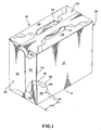
- FIG. 1 shows a carton 10 according to the invention, having an improved article dispenser while FIG. 4 shows a carton blank from which the carton 10 is erected.
- the carton 10 is designed to package multiple articles such as twelve beverage cans whereas the blank is formed of a foldable sheet material such as paperboard, corrugated board, plastic sheet or the like.
- the carton 10 comprises a pair of side walls 12 and 14 foldably joined respectively to the opposite side edges of a bottom wall 16 along fold lines 18 and 20.
- the side walls 12 and 14 extend upwardly to their respective upper edges and a top wall 22 is foldably joined to the upper edges of the side walls 12 and 14 along fold lines 24 and 26.
- an open-ended tubular structure is formed by the top, bottom and side walls 22, 16, 12 and 14.
- the top wall 22 is formed of two top lap panels 28 and 30 glued together in an overlapping relationship as is known in the art.
- the stippling along the upper end portion of the blank in FIG. 4 indicates the area where glue is applied for the purpose of securing the top lap panels 28 and 30.
- the top lap panels 28 and 30 are provided with handle means for carrying the carton. Such handle means is shown in the form of a pair of hand openings 32 and 34 in the top lap panels 28 and 30.
- an end closure structure shown generally by the numerals 36 and 38.
- the end closure structures 36 and 38 in FIG. 1 are shown as fully closing the respective ends of the tubular structure; however they may be designed to partially close one or both ends of the carton.
- An example of a beverage can carton having partially closed ends is shown in U.S. Patent No. 3,894,681 which is hereby incorporated by reference.
- the corner windows shown in this U.S. patent may be employed at least at the two upper corners of the carton 10.
- the end closure structure 36 comprises a bottom end flap 40, a pair of side end flaps 42 and 44, top end flaps 46 and 48 and a pair of web panels 50 and 52.
- the bottom end flap 40 is foldably joined to the bottom wall 16 along a fold line 54.
- the side end flaps 42 and 44 are foldably joined to the side walls 12 and 14 along fold lines 56 and 58, respectively.
- the top end flaps 46 and 48 are foldably joined to the top lap panels 28 and 30 along fold lines 60 and 62, respectively.
- the web panel 50 interconnects the side end flap 42 and the bottom end flap 40 while the web panel 52 interconnects the side end flap 42 and the top end flap 46.
- the web panel 50 is foldably joined to the bottom end flap 40 along a tear line 64 and to the side end flap 42 along a fold line 66 whereas the web panel 52 is foldably joined to the top end flap 46 along a fold line 68 and to the side end flap 42 along a fold line 70.
- These web panels 50 and 52 are formed respectively with apertures 72 and 74 for facilitating folding of the top, bottom and side end flaps 46, 40 and 42.
- the bottom end flap 40 is folded upwardly along the fold line 54 to take the vertical position.
- the top end flaps 46 and 48 are glued together in an overlapping relationship and are folded down along the fold lines 60 and 62 to take the vertical position.
- the side end flaps 42 and 44 are folded toward each other along the fold lines 56 and 58 to take the respective closed positions. In these positions, the side end flaps 42 and 44 are glued together in an overlapping relationship to traverse the respective end of the carton.
- the side end flaps 42 and 44 cover the exterior of the top and bottom end flaps 46, 48 and 40 except the upper end area of the top end flaps 46 and 48 and the lower end area of the bottom end flap 40.
- the web panel 50 is tucked between the side end flap 42 and the bottom end flap 40 while the web panel 52 is tucked between the side end flap 42 and the top end flap 46.
- the web panel 50 In the tucked position, the web panel 50 is folded along the lines 64 and 66 and in a face-contacting relationship with the inside surface of the side end flap 42 and the outside surface of the bottom end flap 40.
- the web panel 52 when in the tucked position, is folded along the fold lines 68 and 70 and in a face-contacting relationship with the inside surface of the side end flap 42 and the outside surface of the top end flap 46.
- the side end flap 44 may be secured to the exterior of the top and bottom end flaps 40, 46 and 48 by means of glue applied thereto as shown by the stippling in FIG. 4. However, the side end flap 42 is merely in contact with the top and bottom end flaps 46 and 40 without glue.
- the web panels 50 and 52 simultaneously take the respective tucked positions.
- the other end closure structure 38 comprises a similar set of end flaps connected to the tubular structure in virtually the same way. Therefore, the parts of the structure 38 corresponding to those of the structure 36 are designated by similar reference numerals with the subscript "a”, and the description thereof is omitted.
- a can dispenser 80 is formed in part in the end closure structure 36 and in part in the side wall 12 as best shown in FIG. 1.
- the dispenser 80 facilitates customer's access to the cans C (FIGS. 3 and 4) packaged in the carton 10.
- the dispenser 80 as is described later in more detail, comprises tear lines 64 and 84 and a frangible line 86.
- the "tear line” or the "frangible line” in this application refer to a perforated slit which is formed in the sheet material from which the carton is formed and functions to split a part of the paperboard material in two.
- the "perforated slit” refers to a line consisting of a series of short slits or cuts arranged at spacings and ready to split along the line when subject to external force.
- the tear line 84 emanates from the lower edge of the side end flap 42, extends upwardly and curves toward the corner fold line 56.
- the tear line 84 then extends into the side wall 12, curves downwardly and terminates on the junction (i.e., fold line 18) between the side wall 12 and the bottom wall 16.
- the frangible line 86 connects between the terminal end of the tear line 84 and the aperture 72 as best shown in FIG. 4.
- the frangible line 86 is shown as being in registry with the fold line 18. However, the frangible line 86 may be formed within the side wall 12 such that it extends between the aperture 72 and a location along the tear line 84.
- the sheet material surrounded by the tear line 84, the frangible line 86, the aperture 72 and the fold line 66 provides a tear panel 82 that is a part of the dispenser 80 and may be torn off of the carton to define an access opening in the carton.
- the tear panel 82 is formed in part from the side end flap 42 and in part from the side wall 12 so that it is located astride the corner fold line 56.
- the maximum vertical size VS of the tear panel 82 typically, is greater than the maximum diameter of the cans C in the carton and less than a size twice as large as the can diameter.
- a preferred vertical size VS of the tear panel 82 is such that push tab 90 that will be described later is disposed at the location between the lowermost can C and the second lowermost can C as viewed in FIG. 4.
- the maximum horizontal size HS of the tear panel 82 may be around the size of the can diameter, and preferably less than the can diameter and greater than a half of the can diameter.
- the tear panel 82 is formed with a generally V-shaped fold line 88 that extends transversely of the corner fold line 56.
- the fold line 88 defines at the upper end portion of the tear panel 82 a push tab 90 for facilitating cutting of the tear panel 82.
- the push tab 90 is hingedly connected to the tear panel 82 along the fold line 88.
- the portion of the fold line 88 within the side wall 12 and the portion thereof within the side end flap 42 diverge upwardly from the corner fold line 56 to define an obtuse angle therebetween as viewed in FIG. 4.
- the fold line 88 may be a smoothly curved line rather than the V-shaped line as long as it lies concave to the push tab 90 when the side wall 12 and the side end flap 42 lie flat in the same plane.
- the tear panel 82 is connected to the bottom end flap 40 through the web panel 50, and in fact the web panel 50 is tucked between the tear panel 82 and the bottom end flap 40.
- the push tab 90 is manually pressed inwardly of the carton till the length of the tear line 84 near the corner fold line 56 breaks to sever the push tab 90 from the carton. This severing is facilitated as a result of the arrangement in which the push tab 90 is located astride the corner fold line 56.
- the side wall 12 and the side end flap 42 act as braces for each other and provide in response to pressing on the push tab 90 resistance strong enough to induce adequate shearing stress along the tear line 84.
- the push tab 90 is easily severed as a result also of the fact that the push tab 90 is located within a single wall area where no layer of sheet material forms the carton wall but the side wall 12 and the side end flap 42.
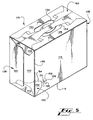
- the push tab 90 is folded inwardly along the fold line 88. This is best shown in FIG. 2.
- the tear panel 82 is then caught at the folded tab 90 by a finger and pulled outwardly and downwardly, which completes breaking of the tear line 84 to its opposite lower ends.
- Successive outward pulling of the tear panel 82 breaks the tear line 64 and then the frangible line 86. This causes the tear panel 82 to be torn out of the carton together with the web panel 50 as shown in FIG. 3 wherein the adjacent can C in the carton 10 is partially exposed through an access opening created by the removal of the tear panel 82.
- the bottom end flap 40 remains undisturbed in the upright position even after the removal of the tear panel 82 because the side end flap 44 adhesively holds the bottom end flap 40 in position and the web panel 50 has been easily detached due to the tear line 64.
- the bottom end flap 40 serves as a stopper for preventing the cans C from spontaneously rolling out of the carton 10 through the access opening.
- Removal of the adjacent can C from the carton 10 may be seen by referring to FIG. 3.
- the user may place two fingers on diagonally opposed portions on the side wall of the adjacent can C, and move the can C in the direction shown by the arrow AR1 through the access opening while slightly pivoting the can in the direction of the arrow AR2.
- the pivoting force flexes the bottom end flap 40, thereby permitting the can C to be pulled outwardly through the access opening.
- cans positioned above the removed can will drop downwardly, thereby presenting another can for removal from the carton.
- the tear panel 82 is detachably connected to the bottom end flap 40 through the web panel 50 and to the bottom wall 16 along the frangible line 86 to allow itself to be completely severed from the carton 10.
- the tear panel 82 may be detachably connected to the web panel 50 by replacing the fold line 66 with a tear line.
- the tear line 64 may, of course, be replaced by a fold line.
- both the tear line 64 and the frangible line 86 may be replaced by fold lines so that the tear panel 82 may remain hingedly connected to the carton 10 after the tear line 84 has been broken.
- the tear panel 82 may be manually swung downwardly about the fold line 18 till it lies in the plane of the bottom wall 16.
- the web panel 50 is unfolded to extend between the tear panel 82 and the bottom end flap 40. This forms a dispensing spout projecting in the direction of the arrow AR1.
- the cans C may then be taken out of the carton 10 one by one through the access opening in the same way as described in the preceding paragraph.
- the corner on which the tear panel 82 may be located is not limited to the corner where two carton walls meet at a right angle.
- the tear panel 82 may also be used on corners where two walls meet at an angle either less or greater than a right angle.
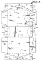
- FIGS. 5-8 illustrate an alternative embodiment of carton of the invention.
- the dispenser 180 of the carton 110 of this embodiment has a partially V-shaped tear line 184 in place of the inverted U-shaped tear line in FIG. 1.
- the tear line 184 emanates from the lower edge of the side end flap 144, extends into the side end flap 142 and reaches the corner fold line 156.
- the tear line 184 then extends obliquely downwardly into the side wall 112, bends downwardly at an acute angle and terminates at the lower corner of the side wall 112 adjacent to the aperture 172.
- the tear panel 182 that is defined by the tear line 184 is formed in part from the side end flap 144, in part from the side end flap 142 and in part from the side wall 112.
- the web panel 150 is connected to the tear panel 182 along a fold line 166 and to the bottom end flap 140 along a tear line 164.
- the fold line 166 may be replaced by a tear line while the tear line 164 may be replaced by a fold line.
- the tear panel 182 is formed with a fold line 188 that extends vertically across of the triangular portion of the tear panel 182 that is defined by the V-shaped portion of the tear line 184.
- the fold line 188 is formed entirely within the side wall 112 and thus does not intersect the corner fold line 156.
- the fold line 188 defines a hingedly connected push tab 190 adjacent to the tip end of the tear panel 182 or near the corner of the V-shaped portion of the tear line 184.
- the dispenser 180 further comprises an arched outer fold line 192 formed in the side wall 112.
- the outer fold line 192 is arranged to partially surround the push tab 190.
- a cut line 194 extends between the outer fold line 192 and the push tab 190 to split the material between the tab 190 and the line 192. As a result, a pair of yielding tabs 196 and 198 are defined between the tab 190 and the fold line 192. In FIG. 8, the cut line 194 is shown as extending into the push tab 190. However, the portion of the cut line 194 within the push tab 190 may be omitted from the push tab 190.
- the location of the push tab 190 relative to the cans in the carton 110 is such that the push tab 190 is registered with the indentation at a can end such as the end of the lowermost can C as shown in FIG. 7.
- the remainder of the carton 110 is virtually identical to the carton of the preceding embodiment, and thus the parts of the carton 110 corresponding to those of the preceding embodiment are denoted by similar reference numerals that are greater by 100 than the corresponding parts of the preceding embodiment and the description thereof is omitted.
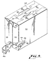
- Removal of the cans C using the dispenser 180 can be seen referring to FIG. 6.
- the user presses inwardly on the push tab 190, which is easily separated from the side wall 120 due to the arrangement including the yielding tabs 196 and 198.
- the yielding tabs 196 and 198 yield to the pressing force and fold inwardly along the outer fold line 192.
- the yielding tabs 196 and 198 fold also along the tear line 184. This causes the push tab 190 to be folded at a sharpest possible angle with respect to the yielding tabs 196 and 198, which promotes breaking of the portion of the tear line 184 flanked by the yielding tabs 196 and 198.
- the push tab 190 Upon the separation from the side wall 112, the push tab 190 is folded inwardly along the fold line 188.
- the tear panel 182 is then caught at the folded tab 190 by a finger and pulled outwardly till breaking of the tear line 184 is completed to its opposite ends.
- the tear line 164 also breaks as a result of the pulling action on the tear panel 182.
- the adjacent can C in the carton 110 is partially exposed through the access opening. Removal of the adjacent can C may be achieved in the virtually same manner as in the preceding embodiment.
- FIG. 9 illustrates a modified form of the dispenser in FIG. 8.
- the tear panel 282 of the dispenser 280 in this modification has a rounded tip end defined by the rounded corner portion of the tear line 284.
- the remainder of the dispenser 280 is virtually identical to that in FIG. 8.
- the parts of the dispenser 280 corresponding to that in FIG. 8 are denoted by similar reference numerals that are greater by 100 than the corresponding parts in FIG. 8 and the description thereof is omitted.
- FIG. 10 illustrates another modified form of the dispenser in FIG. 8.
- the tear panel 382 of the dispenser 380 in this modification has a generally squared tip end defined by the generally squared corner portion of the tear line 384.
- the outer fold line 392 is also squared to correspond to the shape of the corner portion of the tear line 384.
- Two separate cut lines 394a and 394b extend between the outer fold line 392 and the push tab 390.
- three yielding tabs 396, 398 and 400 are defined between the outer fold line 392 and the push tab 390.
- the remainder of the dispenser 380 is virtually identical to that in FIG. 8.
- the parts of the dispenser 380 corresponding to that in FIG. 8 are denoted by similar reference numerals that are greater by 200 than the corresponding parts in FIG. 8 and the description thereof is omitted.
- the carton of the invention may be formed with beveled corner panels each interposed and foldably connecting between a top or bottom end flap and the adjacent one of the top and bottom walls.
- the beveled corner panels are shown in U.S. Patent No. 4,364,509. It should be further appreciated that as used herein, the terms “top”, “bottom” and “side” with respect to the panels or walls of the carton or carton blank are relative terms, and that the carton may be re-oriented as necessary or as desired.
Claims (11)
- Schachtel (10) für eine Vielzahl von Getränkebehältern (c), wobei die Schachtel eine Abreißwandfläche (82) umfasst, deren Entfernung eine Öffnung bereitstellt, durch die die Getränkebehälter einer nach dem anderen sukzessive entnommen werden können, wobei die Abreißwandfläche durch eine Reißlinie (84) definiert wird, die in zwei angrenzenden Wandflächen (12, 42) der Schachtel ausgebildet ist, und den Boden der Schachtel in einer der Wandflächen trifft, dadurch gekennzeichnet, dass sich die Abreißwandfläche über eine Eckfaltlinie (56) der Schachtel erstreckt und eine integrale Drücklasche (90) als Teil davon umfasst, die sich von einer quer verlaufenden Faltlinie (88) erstreckt, die sich rittlings der Eckfaltlinie erstreckt, um einen zerbrechlichen Teil der Abreißwandfläche bereitzustellen, der zerrissen werden kann, um das Entfernen der Abreißwandfläche durch ein Scheren entlang der Reißlinie einzuleiten.
- Schachtel nach Anspruch 1, wobei sich die quer verlaufende Faltlinie quer über die Abreißwandfläche erstreckt, so dass die Drücklasche zwischen der quer verlaufenden Faltlinie und einem Teil der Reißlinie definiert ist.
- Schachtel nach Anspruch 1 oder 2, wobei die quer verlaufende Faltlinie einen ersten Abschnitt und einen zweiten Abschnitt umfasst, wobei der erste Abschnitt an einem Abschnitt der Reißlinie innerhalb der ersten Wand beginnt und sich zu der Eckfaltlinie erstreckt, wobei der zweite Abschnitt an einem Abschnitt der Reißlinie innerhalb der zweiten Wand beginnt und sich zu der Eckfaltlinie erstreckt und wobei der erste und der zweite Abschnitt der quer verlaufenden Faltlinie auf der Eckfaltlinie konvergieren, so dass die quer verlaufende Faltlinie im Allgemeinen V-förmig ist, wenn die erste und die zweite Wand flach in einer Ebene liegen.
- Schachtel nach Anspruch 3, wobei der erste und der zweite Abschnitt der quer verlaufenden Faltlinie einen stumpfen Winkel dazwischen definieren, wenn die erste und die zweite Wand flach in einer Ebene liegen.
- Schachtel nach Anspruch 3, wobei die quer verlaufende Faltlinie konkav zu der Drücklasche verläuft, wenn die erste und die zweite Wand flach in einer Ebene liegen.
- Schachtel (10), umfassend Deckenwände (28, 30) und Bodenwände (16), die durch ein Paar von gegenüber liegenden Seitenwänden (12, 14) miteinander verbunden sind, um eine röhrenförmige Struktur auszubilden, sowie eine Endverschlussstruktur, die an jedem Ende der röhrenförmigen Struktur bereitgestellt ist, um wenigstens teilweise jedes Ende zu verschließen, wobei eine oder jede der Endverschlussstrukturen eine Seitenendklappe (42) umfasst, die mit einer der Seitenwände entlang einer Eckfaltlinie (56) verbunden ist und sich in Richtung der anderen Seitenwand erstreckt, sowie eine Reißlinie (84), die in der einen Seitenwand ausgebildet ist und sich in die Seitenendklappe erstreckt, um eine Reißwandfläche (82) zu definieren, die rittlings der Eckfaltlinie angeordnet ist, dadurch gekennzeichnet, dass die Reißwandfläche eine Drücklasche (90) als Teil davon umfasst, die sich von einer quer verlaufenden Faltlinie (88) erstreckt, die sich rittlings der Eckfaltlinie erstreckt.
- Schachtel (110), umfassend eine erste Wand (112) und eine Gegenstandsabgabevorrichtung, wobei die Gegenstandsabgabevorrichtung eine Reißwandfläche (182) umfasst, die in der ersten Wand durch eine Reißlinie (184) definiert ist, so dass dann, wenn die erste Wand entlang der Reißlinie gestanzt wird, eine Zugangsöffnung ausgebildet wird, um den Zugang zu Gegenständen (c) innerhalb der Schachtel zu ermöglichen, wobei die Reißwandfläche dadurch gekennzeichnet ist, dass eine Drücklasche (190) als Teil davon umfasst wird, die sich von einer ersten Faltlinie (188) erstreckt, um das Stanzen der ersten Wand entlang der Reißlinie zu erleichtern, sowie eine zweite Faltlinie (192), die in der ersten Wand ausgebildet ist und angeordnet ist, um wenigstens teilweise die Drücklasche zu umgeben, so dass wenigstens zwei nachgebende Laschen (196, 198) zwischen der Drücklasche und der zweiten Faltlinie definiert sind.
- Schachtel nach Anspruch 7, wobei die Reißlinie im Allgemeinen V-förmig ist und die Drücklasche angrenzend an eine Ecke der V-förmigen Reißlinie angeordnet ist.
- Schachtel nach Anspruch 7 oder 8, wobei die Reißlinie erste und zweite Abschnitte umfasst, die von der Ecke divergieren, und die erste Faltlinie sich zwischen dem ersten und dem zweiten Abschnitt erstreckt, um quer über die Reißwandfläche zu liegen.
- Schachtel nach einem der Ansprüche 7 bis 9, wobei die Abgabevorrichtung ferner einer. Stanzlinie umfasst, die sich zwischen der zweiten Faltlinie und der Drücklasche erstreckt, um eine Grenze zwischen den nachgebenden Laschen zu definieren.
- Schachtelzuschnitt zum Ausbilden einer Schachtel gemäß einem der Ansprüche 1 bis 5, 6 oder 7 bis 10.
Priority Applications (1)
| Application Number | Priority Date | Filing Date | Title |
|---|---|---|---|
| EP06009955A EP1698565A3 (de) | 2000-11-15 | 2001-11-14 | Kartonschachtel mit Ausgabeeinrichtung |
Applications Claiming Priority (3)
| Application Number | Priority Date | Filing Date | Title |
|---|---|---|---|
| US712871 | 1991-06-12 | ||
| US09/712,871 US6478219B1 (en) | 2000-11-15 | 2000-11-15 | Carton with article dispenser |
| PCT/US2001/044149 WO2002040358A2 (en) | 2000-11-15 | 2001-11-14 | Carton with article dispenser |
Related Child Applications (1)
| Application Number | Title | Priority Date | Filing Date |
|---|---|---|---|
| EP06009955A Division EP1698565A3 (de) | 2000-11-15 | 2001-11-14 | Kartonschachtel mit Ausgabeeinrichtung |
Publications (2)
| Publication Number | Publication Date |
|---|---|
| EP1335860A2 EP1335860A2 (de) | 2003-08-20 |
| EP1335860B1 true EP1335860B1 (de) | 2006-06-28 |
Family
ID=24863892
Family Applications (2)
| Application Number | Title | Priority Date | Filing Date |
|---|---|---|---|
| EP01990717A Expired - Lifetime EP1335860B1 (de) | 2000-11-15 | 2001-11-14 | Kartonschachtel mit ausgabeeinrichtung |
| EP06009955A Withdrawn EP1698565A3 (de) | 2000-11-15 | 2001-11-14 | Kartonschachtel mit Ausgabeeinrichtung |
Family Applications After (1)
| Application Number | Title | Priority Date | Filing Date |
|---|---|---|---|
| EP06009955A Withdrawn EP1698565A3 (de) | 2000-11-15 | 2001-11-14 | Kartonschachtel mit Ausgabeeinrichtung |
Country Status (13)
| Country | Link |
|---|---|
| US (2) | US6478219B1 (de) |
| EP (2) | EP1335860B1 (de) |
| JP (1) | JP4112977B2 (de) |
| AT (1) | ATE331668T1 (de) |
| AU (2) | AU3048002A (de) |
| BR (1) | BR0115428A (de) |
| CA (1) | CA2432587C (de) |
| DE (1) | DE60121205T2 (de) |
| DK (1) | DK1335860T3 (de) |
| ES (1) | ES2267847T3 (de) |
| MX (1) | MXPA03004323A (de) |
| PT (1) | PT1335860E (de) |
| WO (1) | WO2002040358A2 (de) |
Families Citing this family (90)
| Publication number | Priority date | Publication date | Assignee | Title |
|---|---|---|---|---|
| JPH05222737A (ja) * | 1992-01-31 | 1993-08-31 | Matsusaka Eng:Kk | 地中タンクのマンホール装置 |
| US6578736B2 (en) | 2001-01-09 | 2003-06-17 | Riverwood International Corporation | Carton with an improved dispensing feature |
| US6866186B2 (en) | 2002-10-16 | 2005-03-15 | Graphic Packaging International, Inc. | Carton with a dispenser in the top panel for dispensing pouches |
| US20040089671A1 (en) | 2002-11-07 | 2004-05-13 | The C.W. Zumbiel Company | Carton with dispenser |
| US6604677B1 (en) * | 2003-02-06 | 2003-08-12 | Riverwood International Corporation | Carton with top dispensing feature |
| US6869009B2 (en) * | 2003-02-06 | 2005-03-22 | Graphic Packaging International, Inc. | Carton with top dispensing feature |
| US7874477B2 (en) * | 2003-02-06 | 2011-01-25 | Graphic Packaging International, Inc. | Carton with top dispensing feature |
| US6918487B2 (en) | 2003-02-12 | 2005-07-19 | Graphic Packaging International, Inc. | Dispensing system for double stack carton |
| US6974072B2 (en) * | 2003-02-22 | 2005-12-13 | Graphic Packaging International, Inc. | Paperboard carton with a new type of dispenser |
| US6860400B2 (en) * | 2003-03-18 | 2005-03-01 | Caraustar Custom Packaging | Container with friction dispenser |
| US6902104B2 (en) * | 2003-03-26 | 2005-06-07 | Meadwestvaco Packaging Systems, Llc | Carton with dispenser |
| US6997316B2 (en) * | 2003-03-28 | 2006-02-14 | Graphic Packaging International, Inc. | Can dispensing package |
| US7147143B2 (en) | 2003-08-01 | 2006-12-12 | Meadwestvaco Packaging Systems, Llc | Opening assist to dispensing carton |
| US7614497B2 (en) * | 2003-10-15 | 2009-11-10 | Graphic Packaging International, Inc. | Display/vending carton |
| RU2006118783A (ru) * | 2003-10-31 | 2007-12-10 | МИДВЕСТВАКО ПЭКЭДЖИНГ СИСТЕМЗ ЭлЭлСи (US) | Коробка с признаком выдачи банок |
| US20050109827A1 (en) * | 2003-11-24 | 2005-05-26 | Martin Chris L. | Dryer sheet and cleansing article dispensing cartons and die-cut blanks for making the same |
| US7000803B2 (en) * | 2003-12-02 | 2006-02-21 | The C.W. Zumbiel Company | Contoured carton with dispenser |
| US7401711B2 (en) * | 2004-02-10 | 2008-07-22 | Graphic Packaging International, Inc. | Carton having improved opening features |
| US20050189405A1 (en) * | 2004-02-27 | 2005-09-01 | Jean-Manuel Gomes | Three by four can package dispensing carton |
| US7185762B2 (en) * | 2004-03-25 | 2007-03-06 | Neal Patrick Ferris | Product display bag |
| US7337942B2 (en) * | 2004-05-27 | 2008-03-04 | The Coca-Cola Company | Carton |
| US20050274638A1 (en) * | 2004-06-09 | 2005-12-15 | Georgia-Pacific Corporation | Combination shipping container and dispenser |
| US20060054522A1 (en) * | 2004-09-14 | 2006-03-16 | The Coca-Cola Company | Carton with article opening |
| US7712653B2 (en) | 2004-09-29 | 2010-05-11 | Graphic Packaging International, Inc. | Carton with dispenser having access features |
| US7374043B2 (en) * | 2004-10-14 | 2008-05-20 | Mead Westvaco Packaging Systems, Llc | Carton with side accessible dispenser |
| EP1802529A1 (de) * | 2004-10-20 | 2007-07-04 | The Coca-Cola Company | Karton mit artikelöffnung |
| CA2584314C (en) * | 2004-10-29 | 2011-07-05 | Graphic Packaging International, Inc. | Carton having opening features |
| PT1814792E (pt) * | 2004-11-03 | 2009-10-12 | Graphic Packaging Int Inc | Distribuidor de canto para caixas de cartão |
| US20060108406A1 (en) * | 2004-11-22 | 2006-05-25 | The Coca-Cola Company | Carton with article opening |
| WO2007013976A2 (en) | 2005-07-22 | 2007-02-01 | Graphic Packaging International, Inc. | Carton with opening feature and blank |
| US20070095697A1 (en) * | 2005-09-02 | 2007-05-03 | Jean-Michel Auclair | Carton with dispenser |
| NZ571040A (en) | 2006-03-13 | 2011-05-27 | Graphic Packaging Int Inc | Carton with a tear-out dispenser opening |
| US7478745B2 (en) * | 2006-03-31 | 2009-01-20 | International Paper Company | Container and blank having easy opening feature |
| AU2007233313B2 (en) | 2006-04-04 | 2011-03-10 | Graphic Packaging International, Llc | Carton with dispenser |
| FR2901248B1 (fr) * | 2006-05-19 | 2010-09-17 | Airsec | Dispositif distributeur/limiteur de debit de produits unitaires, integre a un conteneur et de traitement in-situ de son atmosphere interne |
| CA2654741A1 (en) | 2006-06-23 | 2007-12-27 | Graphic Packaging International, Inc. | Carton with dispenser |
| ES2492920T3 (es) | 2006-06-23 | 2014-09-10 | Graphic Packaging International, Inc. | Caja de cartón con distribuidor |
| US7648061B2 (en) * | 2006-06-23 | 2010-01-19 | Graphic Packaging International, Inc. | Carton with dispenser |
| JP2008078205A (ja) * | 2006-09-19 | 2008-04-03 | Fujitsu Ltd | 基板組立体及びその製造方法、電子部品組立体及びその製造方法、電子装置 |
| US7713342B2 (en) * | 2006-12-19 | 2010-05-11 | Xerox Corporation | Phase change inks |
| JP4702401B2 (ja) * | 2008-06-02 | 2011-06-15 | カシオ計算機株式会社 | カメラ、カメラ制御プログラム及びカメラ制御方法 |
| EP2379421B1 (de) | 2009-01-16 | 2015-09-23 | Graphic Packaging International, Inc. | Karton mit verstärkungseinsatz |
| BRPI1007860B1 (pt) | 2009-03-17 | 2020-09-24 | Graphic Packaging International, Llc | Caixa para conter uma pluralidade de artigos, matriz para moldar uma caixa, e método de montagem de uma caixa |
| EP2454168B1 (de) | 2009-07-14 | 2015-09-02 | Graphic Packaging International, Inc. | Karton mit einsatz |
| BR112012004017B1 (pt) | 2009-08-28 | 2020-12-29 | Graphic Packaging International, Llc | caixa para reter uma pluralidade de recipientes, matriz de caixa e um elemento de reforço para formar uma caixa, e método para formar uma caixa |
| US20110049227A1 (en) * | 2009-09-01 | 2011-03-03 | Green Bay Converting, Inc. | Blank for forming a carton and a method of recycling hollow cores back into the carton |
| US20110048993A1 (en) * | 2009-09-01 | 2011-03-03 | Green Bay Converting, Inc. | Blank for Forming a Carton and a Method of Inserting Empty Hollow Cores Back into the Carton |
| US8459538B2 (en) * | 2009-12-10 | 2013-06-11 | Federal Express Corporation | Corrugated box with an improved opening system |
| US8281979B1 (en) | 2009-12-11 | 2012-10-09 | John Pfanstiehl | Can dispenser for a carton |
| US8602209B2 (en) | 2010-05-19 | 2013-12-10 | Graphic Packaging International, Inc. | Package for containers |
| CA2794869C (en) | 2010-05-25 | 2014-07-29 | Graphic Packaging International, Inc. | Carton with insert |
| CA2804202C (en) | 2010-07-30 | 2015-02-03 | Graphic Packaging International, Inc. | Carrier for bottles |
| WO2012037446A2 (en) | 2010-09-17 | 2012-03-22 | Graphic Packaging International, Inc. | Carton with insert |
| BR112013013405B1 (pt) | 2010-12-03 | 2020-05-05 | Graphic Packaging Int Inc | embalagem, matriz para formar um carregador, e método para formar uma embalagem |
| US20120261432A1 (en) * | 2011-04-18 | 2012-10-18 | Walling Bradford J | Cartons for dispersing systems |
| US9284084B2 (en) | 2011-05-06 | 2016-03-15 | Graphic Packaging International, Inc. | Carton with article protection feature |
| US9022217B2 (en) | 2011-05-06 | 2015-05-05 | Graphic Packaging International, Inc. | Carton with article protection feature |
| EP2707307B1 (de) | 2011-05-13 | 2017-08-02 | Graphic Packaging International, Inc. | Behälterverpackung |
| US8955674B2 (en) | 2011-08-05 | 2015-02-17 | Graphic Packaging International, Inc. | Package for containers |
| BR112014009736B1 (pt) | 2011-10-19 | 2020-09-29 | Graphic Packaging International, Llc | Método de embalagem de artigos, e máquina de embalagem para fazer a embalagem de uma série de artigos dentro de uma série de embalagens de acondicionamento |
| US8967380B2 (en) | 2012-04-27 | 2015-03-03 | Graphic Packaging International, Inc. | Carton with reinforcing insert |
| CN104284843B (zh) | 2012-05-11 | 2016-05-25 | 印刷包装国际公司 | 具有把手的纸板箱 |
| BR112014032487B1 (pt) | 2012-07-17 | 2021-09-14 | Graphic Packaging International, Llc | Caixa destinada a reter combinação de uma matriz uma pluralidade de recipientes, de caixa e uma inserção de reforço para formar uma caixa destinada a reter uma pluralidade de recipientes, e método para formar uma caixa destinada a reter uma pluralidade de recipientes |
| CN104470822B (zh) | 2012-07-17 | 2017-02-22 | 印刷包装国际公司 | 具有物品保护折板的纸板箱 |
| EP2882656B1 (de) | 2012-08-10 | 2017-11-29 | Graphic Packaging International, Inc. | Karton mit spender |
| US9010620B2 (en) | 2012-08-10 | 2015-04-21 | Graphic Packaging International, Inc. | Carton with handle |
| WO2014055119A1 (en) | 2012-10-05 | 2014-04-10 | Graphic Packaging International, Inc. | Carton with dispensing feature |
| US9840358B2 (en) | 2013-03-14 | 2017-12-12 | Graphic Packaging International, Inc. | Carton with article protection feature |
| US9701436B2 (en) | 2013-04-10 | 2017-07-11 | Graphic Packaging International, Inc. | Carton with article protection feature |
| ES2665604T3 (es) | 2013-04-10 | 2018-04-26 | Graphic Packaging International, Llc | Caja de cartón con características de protección de los artículos |
| EP2996958B1 (de) | 2013-05-13 | 2018-01-17 | Graphic Packaging International, Inc. | Karton mit einsatz |
| BR112015026720A2 (pt) | 2013-05-13 | 2017-08-22 | Graphic Packaging Int Inc | Embalagem destinada a acondicionar uma pluralidade de recipientes, combinação de uma blanqueta de formação de embalagem e de uma blanqueta de formação de inserto, e método de formação de uma embalagem destinada a acondicionar uma pluralidade de recipientes |
| US10384846B2 (en) | 2013-05-24 | 2019-08-20 | Graphic Packaging International, Llc | Arrangement of containers in a carton |
| AU2014268358B2 (en) * | 2013-05-24 | 2018-09-27 | Graphic Packaging International, Llc | Carton for articles |
| US9845182B2 (en) | 2015-05-07 | 2017-12-19 | Graphic Packaging International, Inc. | Carton with handle |
| US10124943B2 (en) | 2013-09-24 | 2018-11-13 | Owens-Brockway Glass Container Inc. | Dispensing carton for a refrigerator door |
| WO2015061659A1 (en) | 2013-10-25 | 2015-04-30 | Graphic Packaging International, Inc. | Carton with retention features |
| ES2717129T3 (es) | 2013-12-10 | 2019-06-19 | Graphic Packaging Int Llc | Caja de cartón con características de protección de los artículos |
| WO2015105833A1 (en) | 2014-01-07 | 2015-07-16 | Graphic Packaging International, Inc. | Carrier for containers |
| AU2015222912B2 (en) | 2014-02-28 | 2019-10-03 | Graphic Packaging International, Llc | Carton with article protection features |
| EP3116796B1 (de) | 2014-03-11 | 2019-05-08 | Graphic Packaging International, LLC | Karton mit einsatz |
| US10322845B2 (en) | 2014-03-11 | 2019-06-18 | Graphic Packaging International, Llc | Carton with insert |
| US10124947B2 (en) | 2014-06-23 | 2018-11-13 | Graphic Packaging International, Llc | Carton with dispensing features |
| NZ730691A (en) | 2014-10-30 | 2018-12-21 | Graphic Packaging Int Llc | Carton with handle |
| KR101580670B1 (ko) * | 2015-05-14 | 2015-12-28 | 대양패키지 주식회사 | 주류용 포장박스 |
| WO2019143671A1 (en) * | 2018-01-19 | 2019-07-25 | Westrock Packaging Systems, Llc | Packaging with features to facilitate opening |
| EP3877289A2 (de) * | 2018-11-09 | 2021-09-15 | WestRock Packaging Systems, LLC | Karton und zuschnitt dafür |
| USD980069S1 (en) | 2020-07-14 | 2023-03-07 | Ball Corporation | Metallic dispensing lid |
| USD993016S1 (en) * | 2021-04-22 | 2023-07-25 | Graphic Packaging International, Llc | Carton |
| WO2023159243A1 (en) * | 2022-02-21 | 2023-08-24 | Westrock Packaging Systems, Llc | Carton and carton blank |
Family Cites Families (28)
| Publication number | Priority date | Publication date | Assignee | Title |
|---|---|---|---|---|
| US2145181A (en) | 1937-12-13 | 1939-01-24 | Kennedy Mary Phyllis | Dispensing box |
| US3019944A (en) * | 1957-12-30 | 1962-02-06 | Kimberly Clark Co | Dispensing carton for flexible sheets |
| US2933229A (en) * | 1958-05-28 | 1960-04-19 | Monte Brice | Milk, oil and fruit container |
| US2974846A (en) * | 1959-05-19 | 1961-03-14 | Diamond National Corp | Carton with reclosing pour spout |
| US3131847A (en) | 1962-10-11 | 1964-05-05 | Alfred E Desmond | Pouring spout construction |
| US3189215A (en) | 1962-10-30 | 1965-06-15 | Weyerhaeuser Co | Article carrier and package |
| US3141596A (en) | 1963-01-03 | 1964-07-21 | Waldorf Paper Prod Co | Dispensing containers |
| US3263861A (en) * | 1964-06-09 | 1966-08-02 | Lawless Bros Container Corp | Dispensing carton |
| US3326364A (en) * | 1965-03-22 | 1967-06-20 | Reynolds Metals Co | Container construction and parts therefor or the like |
| US3404828A (en) | 1967-08-02 | 1968-10-08 | Container Corp | Dispensing carton with siftproof pouring arrangement |
| US3578238A (en) | 1969-07-28 | 1971-05-11 | Weyerhaeuser Co | Container which completely encloses articles |
| US3692227A (en) * | 1970-10-23 | 1972-09-19 | Hoerner Waldorf Corp | Pour spout container |
| US3894681A (en) | 1973-03-26 | 1975-07-15 | Federal Paper Board Co Inc | Carton |
| US4216861A (en) * | 1978-12-04 | 1980-08-12 | The Mead Corporation | Tubular carton |
| US4417661A (en) | 1979-07-05 | 1983-11-29 | Champion International Corporation | Reclosable carton and blank therefor |
| USD263204S (en) | 1979-10-26 | 1982-03-02 | Champion International Corporation | Article carrier blank |
| US4364509A (en) | 1981-06-25 | 1982-12-21 | The Mead Corporation | Article carrier with dispensing feature |
| US4396143A (en) | 1981-08-31 | 1983-08-02 | Manville Service Corporation | Multiple article beverage package |
| US4550834A (en) * | 1983-12-05 | 1985-11-05 | E. I. Du Pont De Nemours & Co. | Self-erecting end-load top-dispensing container |
| US4623074A (en) * | 1985-02-25 | 1986-11-18 | The Procter & Gamble Company | Dual dispensing mode carton and concomitant package |
| US4735315A (en) * | 1987-09-14 | 1988-04-05 | The Mead Corporation | Can carton |
| US4958734A (en) * | 1989-10-10 | 1990-09-25 | The Mead Corporation | End loaded carton having a triple ply wall |
| GB9209521D0 (en) * | 1992-05-01 | 1992-06-17 | Mead Corp | End loading can carton |
| US5368194A (en) | 1993-08-31 | 1994-11-29 | The Mead Corporation | Roll-out dispenser for a beverage carton |
| US5344066A (en) * | 1993-09-29 | 1994-09-06 | Riverwood International Corporation | Carton with reclosable corner pour openings |
| TW309000U (en) * | 1995-12-11 | 1997-06-21 | Riverwood Int Corp | Carrier with article dispenser |
| FR2755423B1 (fr) * | 1996-11-05 | 1998-12-04 | Oxadis | Boite de conditionnement et de distribution d'aliments pour animaux |
| US6176419B1 (en) | 2000-02-29 | 2001-01-23 | The Mead Corporation | Carton with article dispensing feature |
-
2000
- 2000-11-15 US US09/712,871 patent/US6478219B1/en not_active Expired - Lifetime
-
2001
- 2001-11-14 DK DK01990717T patent/DK1335860T3/da active
- 2001-11-14 BR BR0115428-1A patent/BR0115428A/pt not_active IP Right Cessation
- 2001-11-14 AU AU3048002A patent/AU3048002A/xx active Pending
- 2001-11-14 AT AT01990717T patent/ATE331668T1/de not_active IP Right Cessation
- 2001-11-14 AU AU2002230480A patent/AU2002230480B2/en not_active Ceased
- 2001-11-14 PT PT01990717T patent/PT1335860E/pt unknown
- 2001-11-14 CA CA002432587A patent/CA2432587C/en not_active Expired - Fee Related
- 2001-11-14 EP EP01990717A patent/EP1335860B1/de not_active Expired - Lifetime
- 2001-11-14 DE DE60121205T patent/DE60121205T2/de not_active Expired - Fee Related
- 2001-11-14 ES ES01990717T patent/ES2267847T3/es not_active Expired - Lifetime
- 2001-11-14 EP EP06009955A patent/EP1698565A3/de not_active Withdrawn
- 2001-11-14 MX MXPA03004323A patent/MXPA03004323A/es active IP Right Grant
- 2001-11-14 WO PCT/US2001/044149 patent/WO2002040358A2/en active IP Right Grant
- 2001-11-14 JP JP2002542696A patent/JP4112977B2/ja not_active Expired - Fee Related
-
2002
- 2002-07-26 US US10/206,165 patent/US6669083B2/en not_active Expired - Lifetime
Also Published As
| Publication number | Publication date |
|---|---|
| EP1335860A2 (de) | 2003-08-20 |
| ES2267847T3 (es) | 2007-03-16 |
| US6478219B1 (en) | 2002-11-12 |
| CA2432587A1 (en) | 2002-05-23 |
| ATE331668T1 (de) | 2006-07-15 |
| AU3048002A (en) | 2002-05-27 |
| US20020185527A1 (en) | 2002-12-12 |
| JP2004524222A (ja) | 2004-08-12 |
| WO2002040358A3 (en) | 2002-09-12 |
| US6669083B2 (en) | 2003-12-30 |
| DE60121205T2 (de) | 2007-05-16 |
| EP1698565A2 (de) | 2006-09-06 |
| EP1698565A3 (de) | 2008-04-16 |
| DK1335860T3 (da) | 2006-10-30 |
| WO2002040358A2 (en) | 2002-05-23 |
| MXPA03004323A (es) | 2005-07-01 |
| JP4112977B2 (ja) | 2008-07-02 |
| PT1335860E (pt) | 2006-11-30 |
| BR0115428A (pt) | 2003-09-16 |
| AU2002230480B2 (en) | 2006-09-21 |
| DE60121205D1 (de) | 2006-08-10 |
| CA2432587C (en) | 2007-08-07 |
Similar Documents
| Publication | Publication Date | Title |
|---|---|---|
| EP1335860B1 (de) | Kartonschachtel mit ausgabeeinrichtung | |
| AU2002230480A1 (en) | Carton with article dispenser | |
| US6176419B1 (en) | Carton with article dispensing feature | |
| US7832622B2 (en) | Side handles for a carton | |
| EP2121456B1 (de) | Kühlbox mit rundumgriff | |
| US4498581A (en) | Beverage can carton with opening panel | |
| US20050194430A1 (en) | Carton with removable corner portion | |
| US20060131370A1 (en) | Carton with pressure sensitive opening device | |
| US20060081692A1 (en) | Carton with article opening | |
| WO2007038748A1 (en) | Carton with opening access feature | |
| US7147143B2 (en) | Opening assist to dispensing carton | |
| WO2007070485A1 (en) | Carton having a pivotable dispenser | |
| EP0511680A1 (de) | Öffnungskonstruktion für keilförmige Torteschachtel | |
| US5720430A (en) | Dispensing carton with integral pour spout | |
| KR20040093714A (ko) | 카톤 및 카톤 블랭크 | |
| EP3844074B1 (de) | Wiederverschliessbarer karton und zuschnitt dafür | |
| WO2010014659A1 (en) | Carton with opening and blank therefor |
Legal Events
| Date | Code | Title | Description |
|---|---|---|---|
| PUAI | Public reference made under article 153(3) epc to a published international application that has entered the european phase |
Free format text: ORIGINAL CODE: 0009012 |
|
| 17P | Request for examination filed |
Effective date: 20030610 |
|
| AK | Designated contracting states |
Designated state(s): AT BE CH CY DE DK ES FI FR GB GR IE IT LI LU MC NL PT SE TR |
|
| AX | Request for extension of the european patent |
Extension state: AL LT LV MK RO SI |
|
| RAP1 | Party data changed (applicant data changed or rights of an application transferred) |
Owner name: MEADWESTVACO PACKAGING SYSTEMS LLC |
|
| RIN1 | Information on inventor provided before grant (corrected) |
Inventor name: BATES, AARON Inventor name: HOLLEY, JOHN, M, JR |
|
| 17Q | First examination report despatched |
Effective date: 20040730 |
|
| GRAP | Despatch of communication of intention to grant a patent |
Free format text: ORIGINAL CODE: EPIDOSNIGR1 |
|
| GRAS | Grant fee paid |
Free format text: ORIGINAL CODE: EPIDOSNIGR3 |
|
| GRAA | (expected) grant |
Free format text: ORIGINAL CODE: 0009210 |
|
| AK | Designated contracting states |
Kind code of ref document: B1 Designated state(s): AT BE CH CY DE DK ES FI FR GB GR IE IT LI LU MC NL PT SE TR |
|
| PG25 | Lapsed in a contracting state [announced via postgrant information from national office to epo] |
Ref country code: IT Free format text: LAPSE BECAUSE OF FAILURE TO SUBMIT A TRANSLATION OF THE DESCRIPTION OR TO PAY THE FEE WITHIN THE PRESCRIBED TIME-LIMIT;WARNING: LAPSES OF ITALIAN PATENTS WITH EFFECTIVE DATE BEFORE 2007 MAY HAVE OCCURRED AT ANY TIME BEFORE 2007. THE CORRECT EFFECTIVE DATE MAY BE DIFFERENT FROM THE ONE RECORDED. Effective date: 20060628 |
|
| REG | Reference to a national code |
Ref country code: GB Ref legal event code: FG4D |
|
| REG | Reference to a national code |
Ref country code: CH Ref legal event code: EP |
|
| REG | Reference to a national code |
Ref country code: IE Ref legal event code: FG4D |
|
| REF | Corresponds to: |
Ref document number: 60121205 Country of ref document: DE Date of ref document: 20060810 Kind code of ref document: P |
|
| PGFP | Annual fee paid to national office [announced via postgrant information from national office to epo] |
Ref country code: IE Payment date: 20060830 Year of fee payment: 6 |
|
| PGFP | Annual fee paid to national office [announced via postgrant information from national office to epo] |
Ref country code: BE Payment date: 20060911 Year of fee payment: 6 |
|
| PGFP | Annual fee paid to national office [announced via postgrant information from national office to epo] |
Ref country code: DK Payment date: 20060912 Year of fee payment: 6 |
|
| PGFP | Annual fee paid to national office [announced via postgrant information from national office to epo] |
Ref country code: PT Payment date: 20060926 Year of fee payment: 6 |
|
| PGFP | Annual fee paid to national office [announced via postgrant information from national office to epo] |
Ref country code: FI Payment date: 20060927 Year of fee payment: 6 |
|
| REG | Reference to a national code |
Ref country code: SE Ref legal event code: TRGR |
|
| REG | Reference to a national code |
Ref country code: DK Ref legal event code: T3 |
|
| PGFP | Annual fee paid to national office [announced via postgrant information from national office to epo] |
Ref country code: AT Payment date: 20061102 Year of fee payment: 6 |
|
| PGFP | Annual fee paid to national office [announced via postgrant information from national office to epo] |
Ref country code: TR Payment date: 20061108 Year of fee payment: 6 |
|
| PGFP | Annual fee paid to national office [announced via postgrant information from national office to epo] |
Ref country code: CY Payment date: 20061114 Year of fee payment: 6 |
|
| PGFP | Annual fee paid to national office [announced via postgrant information from national office to epo] |
Ref country code: GB Payment date: 20061122 Year of fee payment: 6 |
|
| PGFP | Annual fee paid to national office [announced via postgrant information from national office to epo] |
Ref country code: CH Payment date: 20061124 Year of fee payment: 6 Ref country code: ES Payment date: 20061124 Year of fee payment: 6 |
|
| PGFP | Annual fee paid to national office [announced via postgrant information from national office to epo] |
Ref country code: DE Payment date: 20061128 Year of fee payment: 6 |
|
| PG25 | Lapsed in a contracting state [announced via postgrant information from national office to epo] |
Ref country code: MC Free format text: LAPSE BECAUSE OF NON-PAYMENT OF DUE FEES Effective date: 20061130 |
|
| PGFP | Annual fee paid to national office [announced via postgrant information from national office to epo] |
Ref country code: IT Payment date: 20061130 Year of fee payment: 6 Ref country code: NL Payment date: 20061130 Year of fee payment: 6 |
|
| REG | Reference to a national code |
Ref country code: PT Ref legal event code: SC4A Free format text: AVAILABILITY OF NATIONAL TRANSLATION Effective date: 20060926 Ref country code: CH Ref legal event code: NV Representative=s name: KIRKER & CIE SA |
|
| ET | Fr: translation filed | ||
| REG | Reference to a national code |
Ref country code: ES Ref legal event code: FG2A Ref document number: 2267847 Country of ref document: ES Kind code of ref document: T3 |
|
| RAP2 | Party data changed (patent owner data changed or rights of a patent transferred) |
Owner name: MEADWESTVACO PACKAGING SYSTEMS LLC |
|
| PLBE | No opposition filed within time limit |
Free format text: ORIGINAL CODE: 0009261 |
|
| STAA | Information on the status of an ep patent application or granted ep patent |
Free format text: STATUS: NO OPPOSITION FILED WITHIN TIME LIMIT |
|
| REG | Reference to a national code |
Ref country code: CH Ref legal event code: PFA Owner name: MEADWESTVACO PACKAGING SYSTEMS LLC Free format text: MEADWESTVACO PACKAGING SYSTEMS LLC#ONE HIGH RIDGE PARK#STAMFORD, CONNECTICUT 06905 (US) -TRANSFER TO- MEADWESTVACO PACKAGING SYSTEMS LLC#MEADWESTVACO CORPORATE CENTRE 11013 WEST BROAD STREET#GLEN ALLEN, VIRGINIA 23060 (US) |
|
| REG | Reference to a national code |
Ref country code: PT Ref legal event code: TE4A Owner name: MEADWESTVACO PACKAGING SYSTEMS LLC, US Effective date: 20070419 |
|
| 26N | No opposition filed |
Effective date: 20070329 |
|
| NLT2 | Nl: modifications (of names), taken from the european patent patent bulletin |
Owner name: MEADWESTVACO PACKAGING SYSTEMS LLC Effective date: 20070509 |
|
| BECA | Be: change of holder's address |
Owner name: *MEADWESTVACO PACKAGING SYSTEMS LLCMEADWESTVACO CO Effective date: 20060628 |
|
| PGFP | Annual fee paid to national office [announced via postgrant information from national office to epo] |
Ref country code: SE Payment date: 20060911 Year of fee payment: 6 |
|
| PG25 | Lapsed in a contracting state [announced via postgrant information from national office to epo] |
Ref country code: GR Free format text: LAPSE BECAUSE OF FAILURE TO SUBMIT A TRANSLATION OF THE DESCRIPTION OR TO PAY THE FEE WITHIN THE PRESCRIBED TIME-LIMIT Effective date: 20060929 |
|
| REG | Reference to a national code |
Ref country code: PT Ref legal event code: MM4A Free format text: LAPSE DUE TO NON-PAYMENT OF FEES Effective date: 20080514 |
|
| BERE | Be: lapsed |
Owner name: *MEADWESTVACO PACKAGING SYSTEMS LLC Effective date: 20071130 |
|
| REG | Reference to a national code |
Ref country code: DK Ref legal event code: EBP |
|
| EUG | Se: european patent has lapsed | ||
| GBPC | Gb: european patent ceased through non-payment of renewal fee |
Effective date: 20071114 |
|
| PG25 | Lapsed in a contracting state [announced via postgrant information from national office to epo] |
Ref country code: LI Free format text: LAPSE BECAUSE OF NON-PAYMENT OF DUE FEES Effective date: 20071130 Ref country code: FI Free format text: LAPSE BECAUSE OF NON-PAYMENT OF DUE FEES Effective date: 20071114 Ref country code: CH Free format text: LAPSE BECAUSE OF NON-PAYMENT OF DUE FEES Effective date: 20071130 Ref country code: LU Free format text: LAPSE BECAUSE OF NON-PAYMENT OF DUE FEES Effective date: 20061114 |
|
| REG | Reference to a national code |
Ref country code: CH Ref legal event code: PL |
|
| NLV4 | Nl: lapsed or anulled due to non-payment of the annual fee |
Effective date: 20080601 |
|
| PG25 | Lapsed in a contracting state [announced via postgrant information from national office to epo] |
Ref country code: AT Free format text: LAPSE BECAUSE OF NON-PAYMENT OF DUE FEES Effective date: 20071114 |
|
| PG25 | Lapsed in a contracting state [announced via postgrant information from national office to epo] |
Ref country code: BE Free format text: LAPSE BECAUSE OF NON-PAYMENT OF DUE FEES Effective date: 20071130 Ref country code: CY Free format text: LAPSE BECAUSE OF NON-PAYMENT OF DUE FEES Effective date: 20071114 Ref country code: PT Free format text: LAPSE BECAUSE OF NON-PAYMENT OF DUE FEES Effective date: 20080514 |
|
| PG25 | Lapsed in a contracting state [announced via postgrant information from national office to epo] |
Ref country code: DE Free format text: LAPSE BECAUSE OF NON-PAYMENT OF DUE FEES Effective date: 20080603 Ref country code: DK Free format text: LAPSE BECAUSE OF NON-PAYMENT OF DUE FEES Effective date: 20071130 Ref country code: SE Free format text: LAPSE BECAUSE OF NON-PAYMENT OF DUE FEES Effective date: 20071115 Ref country code: IE Free format text: LAPSE BECAUSE OF NON-PAYMENT OF DUE FEES Effective date: 20071114 Ref country code: NL Free format text: LAPSE BECAUSE OF NON-PAYMENT OF DUE FEES Effective date: 20080601 |
|
| PGFP | Annual fee paid to national office [announced via postgrant information from national office to epo] |
Ref country code: FR Payment date: 20061004 Year of fee payment: 6 |
|
| REG | Reference to a national code |
Ref country code: FR Ref legal event code: ST Effective date: 20080930 |
|
| PG25 | Lapsed in a contracting state [announced via postgrant information from national office to epo] |
Ref country code: GB Free format text: LAPSE BECAUSE OF NON-PAYMENT OF DUE FEES Effective date: 20071114 |
|
| REG | Reference to a national code |
Ref country code: ES Ref legal event code: FD2A Effective date: 20071115 |
|
| PG25 | Lapsed in a contracting state [announced via postgrant information from national office to epo] |
Ref country code: ES Free format text: LAPSE BECAUSE OF NON-PAYMENT OF DUE FEES Effective date: 20071115 Ref country code: FR Free format text: LAPSE BECAUSE OF NON-PAYMENT OF DUE FEES Effective date: 20071130 |
|
| PG25 | Lapsed in a contracting state [announced via postgrant information from national office to epo] |
Ref country code: IT Free format text: LAPSE BECAUSE OF NON-PAYMENT OF DUE FEES Effective date: 20071114 |
|
| PG25 | Lapsed in a contracting state [announced via postgrant information from national office to epo] |
Ref country code: TR Free format text: LAPSE BECAUSE OF FAILURE TO SUBMIT A TRANSLATION OF THE DESCRIPTION OR TO PAY THE FEE WITHIN THE PRESCRIBED TIME-LIMIT Effective date: 20060628 |