EP1335179A1 - Pyrotechnische Zündkette mit einem Anzündträger aus Kunststoff mit integrierter Metalleinlage - Google Patents
Pyrotechnische Zündkette mit einem Anzündträger aus Kunststoff mit integrierter Metalleinlage Download PDFInfo
- Publication number
- EP1335179A1 EP1335179A1 EP03001828A EP03001828A EP1335179A1 EP 1335179 A1 EP1335179 A1 EP 1335179A1 EP 03001828 A EP03001828 A EP 03001828A EP 03001828 A EP03001828 A EP 03001828A EP 1335179 A1 EP1335179 A1 EP 1335179A1
- Authority
- EP
- European Patent Office
- Prior art keywords
- ignition
- plastic
- carrier
- metal insert
- chain according
- Prior art date
- Legal status (The legal status is an assumption and is not a legal conclusion. Google has not performed a legal analysis and makes no representation as to the accuracy of the status listed.)
- Granted
Links
Images



Classifications
-
- F—MECHANICAL ENGINEERING; LIGHTING; HEATING; WEAPONS; BLASTING
- F42—AMMUNITION; BLASTING
- F42B—EXPLOSIVE CHARGES, e.g. FOR BLASTING, FIREWORKS, AMMUNITION
- F42B3/00—Blasting cartridges, i.e. case and explosive
- F42B3/26—Arrangements for mounting initiators; Accessories therefor, e.g. tools
Definitions
- the invention relates to a pyrotechnic ignition chain with an ignition carrier Plastic according to the preamble of claim 1.
- the generic DE-A1-199 60 642 describes a pyrotechnic ignition chain with a plastic ignition carrier.
- An ignition element is in the ignition carrier integrated, which protrudes with its active part from the ignition carrier and protrudes into a metal housing which is attached to the ignition carrier.
- An amplifier charge is arranged in the metal housing.
- the ignition carrier made of plastic has the function of the ignition element mechanically to be securely fixed in the metal housing. In addition, he must ensure that there is no gas between the plastic ignition carrier / ignition element when the ignition chain is functioning and / or plastic lighter carrier / metal housing escape can.
- the ignition carrier has preferably been machined as a combined one Turned, milled part manufactured. This method of production is very expensive.
- the invention is based on the object of a pyrotechnic ignition chain the preamble of claim 1 in terms of tightness and manufacturing costs to improve.
- this object is achieved in that mechanical A metal insert is integrated in the support, the metal insert is encapsulated by the plastic of the ignition carrier.
- the metal insert is a stamped or bent part.
- the plastic of the ignition carrier is advantageously doped with mica.
- the igniter is partially or completely made of the plastic of the igniter molded.
- the ignition element is expediently molded around with plastic wetted with a sealing compound.
- an elastic plastic can be used as the plastic for the ignition carrier be used.
- the metal insert with the ignition element connected.
- the metal insert with the ignition element connected.
- the metal insert is advantageously cup-shaped, the edge of the Metal insert is flanged or folded and led out of the igniter is.
- the invention is characterized in that Instead of the complex machining, a stamped, bent part is used, which as Insert is subsequently overmolded.
- the metal insert or the stamped, bent part takes over mechanical support that with the same strength due to its rigidity can be made with a smaller wall thickness than a turned / milled part; thereby an additional weight saving is achieved.
- the plastic in the ignition carrier ensures the sealing function between the ignition carrier / ignition element and / or ignition carrier / metal housing.
- the required elaborate contour in the contact area of the ignition element can also can be achieved with the plastic by spraying.
- the ignition element and metal housing can be made of the plastic of the ignition carrier be doped with mica. This ensures that the high-resistance plastic becomes low-resistance at high voltage and dissipates the ESD discharges and there is no unwanted triggering.
- the ignition carrier 4 is made Plastic can be used.
- the ignition element 2 is partially extrusion-coated in the ignition carrier 4 and the metal insert 3 integrated.
- the ignition carrier 4 is in turn connected to a sleeve 1, which contains a sealing cup 5 in the lower part, which subsequent booster charge 6 in the installed state against moisture protects and thus the function of the ignition chain safely over the entire period of use guaranteed.
- a vapor barrier can be installed. This can be achieved by e.g. the ignition element 2 with a corresponding one Sealant is wetted after the injection molding due to the Heat and / or shrinking the plastic onto the igniter 2 takes effect.
- Another way to maintain the vapor barrier is that for the areas 13 and 14 an elastic plastic is used. This can e.g. B. in one spraying process (2-component spraying) respectively.
- the plastic can the ignition carrier 4 are doped with mica, as described above is.
- the function of the ignition chain results from the implementation of pyrotechnics in the Ignition element 2 and the downstream booster charge 6 are briefly high Gas pressure, which is also on the igniter 2 and the igniter 4 as axial Force is effective, the igniter 2 in the igniter 4 non-positively sealing presses.
- the igniter 2 In order to avoid that the igniter 2 is inadmissible in the igniter 4 is pressed in and thereby the gas between igniter 2 and Ignition carrier 4 can escape partially or completely unintentionally or in extreme cases the ignition element 2 is pressed by the ignition carrier 4, one must Support in the carrier.
- the metal insert 3 which is integrated in the ignition carrier 4 and securely supports the ignition element 2 in the area 3a, 3b.
- the metal insert 3 is integrated in the ignition carrier 4 and securely supports the ignition element 2 in the area 3a, 3b.
- the shape and The way in which the metal insert 3 is produced as a bent part is highly rigid, which ensures the support safely. This ensures that too no deformation of the metal insert 3 occurs at the highest pressure load.
- the metal insert is used to fix the ignition carrier 4 in the higher-level device 3 designed so that it protrudes from the ignition carrier 4 in the area 3b and can be attached in the higher-level device.
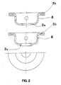
- FIG. 3 A possible form of the metal insert 3 is outlined in FIG. As can be seen from this this part can preferably be manufactured as a stamped part, the following is reshaped accordingly.
- the metal part can e.g. B. have recesses 8 to the positive connection Metal insert 3 - plastic to improve.
- the metal part 3 is folded over for additional reinforcement to obtain.
- the metal insert 3 can also be deformed in the inner region 3a to increase the stiffness as shown at 3c.
- FIG. 3 The contacting of the ignition element 2 in the region 7 is shown in FIG. 3. As can be seen, a contact fuse 9 is required for contacting the held in position in the ignition carrier 4 by means of corresponding cutouts 10 becomes.
- FIG. 4 shows a further possible embodiment of an ignition carrier 4.
- the complete igniter 2 is molded.
- FIG. 5 shows a further technical possibility of arranging the metal insert 3 shown in the ignition carrier 4.
- the metal insert 3 with the igniter 2 connected this can e.g. B. done by welding 12. Thereby an additional mechanical fixation of the two parts is achieved.
- Another advantage is that the spraying process is simplified can be used because only one part (instead of two parts) has to be inserted.
- Booster charge 6 means an amplifier charge and sleeve 1 is a Casing.
Landscapes
- Engineering & Computer Science (AREA)
- General Engineering & Computer Science (AREA)
- Air Bags (AREA)
- Laminated Bodies (AREA)
Abstract
Description
Claims (10)
- Pyrotechnische Zündkette mit einem Anzündträger (4) aus Kunststoff, welcher ein Anzündelement (2) trägt und am Anzündträger (4) ein zylinderförmiges Metallgehäuse (1) befestigt ist, in welches das Anzündelement (2) hineinragt und im Metallgehäuse (1) eine Verstärkerladung (6) angeordnet ist, dadurch gekennzeichnet, dass zur mechanischen Abstützung im Anzündträger (4) eine Metalleinlage (3) integriert ist, wobei die Metalleinlage (3) vom Kunststoff des Anzündträgers (4) umspritzt ist.
- Zündkette nach Anspruch 1, dadurch gekennzeichnet, dass die Metalleinlage (3) ein Stanz- oder Biegeteil ist.
- Zündkette nach Anspruch 1 oder 2, dadurch gekennzeichnet, dass der Kunststoff des Anzündträgers (4) mit Glimmer dotiert ist.
- Zündkette nach einem der Ansprüche 1 bis 3, dadurch gekennzeichnet, dass das Anzündelement (2) teilweise oder vollständig vom Kunststoff des Anzündträgers (4) umspritzt ist.
- Zündkette nach einem der Ansprüche 1 bis 4, dadurch gekennzeichnet, dass das Anzündelement (2) vor dem Umspritzen mit Kunststoff mit einer Dichtmasse benetzt wurde.
- Zündkette nach einem der Ansprüche 1 bis 5, dadurch gekennzeichnet, dass Bereichsweise als Kunststoff für den Anzündträger (4) ein elastischer Kunststoff verwendet wird.
- Zündkette nach einem der Ansprüche 1 bis 6, dadurch gekennzeichnet, dass die Metalleinlage (3) mit dem Anzündelement (2) verbunden ist.
- Zündkette nach einem der Ansprüche 1 bis 7, dadurch gekennzeichnet, dass die Metalleinlage (3) tassenförmig ausgebildet ist.
- Zündkette nach einem der Ansprüche 1 bis 8, dadurch gekennzeichnet, dass der Rand der Metalleinlage (3) umgebördelt oder umgelegt und aus dem Anzündträger (4) herausgeführt ist.
- Zündkette nach einem der Ansprüche 1 bis 9, dadurch gekennzeichnet, dass in der Metalleinlage (3) Aussparungen (8) angeordnet sind.
Applications Claiming Priority (4)
| Application Number | Priority Date | Filing Date | Title |
|---|---|---|---|
| DE10205427 | 2002-02-09 | ||
| DE10205427 | 2002-02-09 | ||
| DE10236508 | 2002-08-09 | ||
| DE10236508A DE10236508A1 (de) | 2002-02-09 | 2002-08-09 | Pyrotechnische Zündkette mit einem Anzündträger aus Kunststoff mit integrierter Metalleinlage |
Publications (3)
| Publication Number | Publication Date |
|---|---|
| EP1335179A1 true EP1335179A1 (de) | 2003-08-13 |
| EP1335179B1 EP1335179B1 (de) | 2007-09-05 |
| EP1335179B2 EP1335179B2 (de) | 2011-08-24 |
Family
ID=27614273
Family Applications (1)
| Application Number | Title | Priority Date | Filing Date |
|---|---|---|---|
| EP03001828A Expired - Lifetime EP1335179B2 (de) | 2002-02-09 | 2003-01-29 | Pyrotechnische Zündkette mit einem Anzündträger aus Kunststoff mit integrierter Metalleinlage |
Country Status (5)
| Country | Link |
|---|---|
| US (1) | US7111558B2 (de) |
| EP (1) | EP1335179B2 (de) |
| AT (1) | ATE372499T1 (de) |
| CZ (1) | CZ2003386A3 (de) |
| DE (1) | DE50308092D1 (de) |
Cited By (1)
| Publication number | Priority date | Publication date | Assignee | Title |
|---|---|---|---|---|
| CN113566662A (zh) * | 2021-06-17 | 2021-10-29 | 北京凯米迈克科技有限公司 | 一种便捷式涉电引火件 |
Families Citing this family (14)
| Publication number | Priority date | Publication date | Assignee | Title |
|---|---|---|---|---|
| US20050183606A1 (en) * | 2002-04-16 | 2005-08-25 | Dairi Kubo | Gas generator |
| US7690303B2 (en) | 2004-04-22 | 2010-04-06 | Reynolds Systems, Inc. | Plastic encapsulated energetic material initiation device |
| DE202005007611U1 (de) * | 2005-05-13 | 2005-09-22 | Trw Airbag Systems Gmbh | Gasgenerator |
| US7854201B2 (en) * | 2005-11-08 | 2010-12-21 | Daicel Chemical Industries, Ltd. | Igniter assembly |
| JP4925894B2 (ja) * | 2007-03-30 | 2012-05-09 | 日産自動車株式会社 | スプリングシートおよびダンパーディスク組立体 |
| US20090114109A1 (en) * | 2007-11-01 | 2009-05-07 | Arc Automotive Inc. | Stamped and molded igniter body for airbag inflators |
| US8100043B1 (en) * | 2008-03-28 | 2012-01-24 | Reynolds Systems, Inc. | Detonator cartridge and methods of use |
| JP5530113B2 (ja) * | 2009-03-26 | 2014-06-25 | 株式会社ダイセル | 点火器の固定構造 |
| US8393641B1 (en) | 2009-06-12 | 2013-03-12 | Tk Holdings, Inc. | Gas generator |
| FR2955932B1 (fr) * | 2010-02-01 | 2012-04-06 | Livbag | Generateur de gaz et son procede de fabrication |
| JP5381932B2 (ja) * | 2010-03-02 | 2014-01-08 | 豊田合成株式会社 | ガス発生装置 |
| JP5293713B2 (ja) * | 2010-09-30 | 2013-09-18 | 豊田合成株式会社 | ガス発生装置 |
| CN105283357B (zh) * | 2013-03-29 | 2017-08-25 | 日本化药株式会社 | 气体发生器 |
| US11808554B1 (en) | 2021-06-24 | 2023-11-07 | United States Of America As Represented By The Secretary Of The Air Force | Embedded mounting devices and methods |
Citations (4)
| Publication number | Priority date | Publication date | Assignee | Title |
|---|---|---|---|---|
| US5936186A (en) * | 1996-05-06 | 1999-08-10 | Trw Occupant Restraint Systems Gmbh | Electrical igniter of a pyrotechnical gas generator |
| EP0943503A2 (de) * | 1998-03-19 | 1999-09-22 | Oea, Inc. | Zünder für Aufblasvorrichtung mit Einsatzkörper |
| EP1043201A2 (de) * | 1999-04-09 | 2000-10-11 | Showa Kinzoku Kogyo Co., Ltd. | Gaserzeugungsvorrichtung mit elektrischer Anzündung |
| DE19960642A1 (de) * | 1999-08-05 | 2001-02-15 | Dynamit Nobel Ag | Pyrotechnische Zündkette |
Family Cites Families (10)
| Publication number | Priority date | Publication date | Assignee | Title |
|---|---|---|---|---|
| US3650212A (en) * | 1970-05-11 | 1972-03-21 | Western Dynamics Inc | Economical, tough, debris-free shaped charge device and perforating gun assembly employing same |
| US3971320A (en) * | 1974-04-05 | 1976-07-27 | Ici United States Inc. | Electric initiator |
| US3906858A (en) * | 1974-07-30 | 1975-09-23 | Us Eneregy Research And Dev Ad | Miniature igniter |
| CH688564A5 (de) † | 1993-08-25 | 1997-11-14 | Ems Patvag Ag | Gekapselter elektrischer Zuender mit integriertem Ueberspannungsableiter fuer einen Gasgenerator. |
| US5733135A (en) † | 1995-12-06 | 1998-03-31 | Trw Inc. | Air bag inflator assembly with shorting clip |
| CZ299491B6 (cs) * | 1999-10-14 | 2008-08-13 | Nippon Kayaku Kabushiki-Kaisha | Vyvíjec plynu |
| US6341562B1 (en) * | 2000-02-22 | 2002-01-29 | Autoliv Asp, Inc. | Initiator assembly with activation circuitry |
| US6644198B1 (en) * | 2000-10-31 | 2003-11-11 | Special Devices, Inc. | Integral pyrotechnic initiator with molded connector |
| AU2002230938A1 (en) * | 2000-10-31 | 2002-05-15 | Special Devices, Inc. | Multi-unit pyrotechnic initiation system |
| US6820556B1 (en) * | 2001-11-21 | 2004-11-23 | Daicel Chemical Industries, Ltd. | Initiator assembly |
-
2003
- 2003-01-29 EP EP03001828A patent/EP1335179B2/de not_active Expired - Lifetime
- 2003-01-29 AT AT03001828T patent/ATE372499T1/de not_active IP Right Cessation
- 2003-01-29 DE DE50308092T patent/DE50308092D1/de not_active Expired - Lifetime
- 2003-01-30 US US10/354,937 patent/US7111558B2/en not_active Expired - Fee Related
- 2003-02-07 CZ CZ2003386A patent/CZ2003386A3/cs unknown
Patent Citations (4)
| Publication number | Priority date | Publication date | Assignee | Title |
|---|---|---|---|---|
| US5936186A (en) * | 1996-05-06 | 1999-08-10 | Trw Occupant Restraint Systems Gmbh | Electrical igniter of a pyrotechnical gas generator |
| EP0943503A2 (de) * | 1998-03-19 | 1999-09-22 | Oea, Inc. | Zünder für Aufblasvorrichtung mit Einsatzkörper |
| EP1043201A2 (de) * | 1999-04-09 | 2000-10-11 | Showa Kinzoku Kogyo Co., Ltd. | Gaserzeugungsvorrichtung mit elektrischer Anzündung |
| DE19960642A1 (de) * | 1999-08-05 | 2001-02-15 | Dynamit Nobel Ag | Pyrotechnische Zündkette |
Cited By (1)
| Publication number | Priority date | Publication date | Assignee | Title |
|---|---|---|---|---|
| CN113566662A (zh) * | 2021-06-17 | 2021-10-29 | 北京凯米迈克科技有限公司 | 一种便捷式涉电引火件 |
Also Published As
| Publication number | Publication date |
|---|---|
| ATE372499T1 (de) | 2007-09-15 |
| US7111558B2 (en) | 2006-09-26 |
| EP1335179B2 (de) | 2011-08-24 |
| EP1335179B1 (de) | 2007-09-05 |
| DE50308092D1 (de) | 2007-10-18 |
| US20030183110A1 (en) | 2003-10-02 |
| CZ2003386A3 (cs) | 2004-08-18 |
Similar Documents
| Publication | Publication Date | Title |
|---|---|---|
| EP1335179B1 (de) | Pyrotechnische Zündkette mit einem Anzündträger aus Kunststoff mit integrierter Metalleinlage | |
| EP0704348A1 (de) | Anzündeinheit für einen Gasgenerator eines passiven Rückhaltesystems | |
| EP3615387A1 (de) | Anzünderträger, baugruppe, gasgenerator sowie verfahren zur herstellung eines gasgenerators | |
| DE102013020526A1 (de) | Polkörper für einen pyrotechnischen anzünder eines gasgenerators, anzünder, gasgenerator und gassackmodul mit einem derartigen polkörper | |
| DE102018111046A1 (de) | Magnet-Baugruppe für eine Sensoreinrichtung eines Kraftfahrzeugs, Sensoreinrichtung mit einer Magnet-Baugruppe und Kraftfahrzeug mit einer Sensoreinrichtung | |
| DE69712385T2 (de) | Fahrzeugzigarettenanzünder mit einer Schutzvorrichtung | |
| EP2165070B1 (de) | Hochspannungsanschluss für eine zündkerze | |
| EP3615388B1 (de) | Anzünderträger, baugruppe, gasgenerator sowie verfahren zur herstellung eines gasgenerators | |
| DE112020004400B4 (de) | Zünder-Baugruppe und Verfahren zum Zusammenbauder Zünder-Baugruppe | |
| DE102004051942C5 (de) | Trägerelement insbesondere zwischen einem Lenkrad und einem Airbagmodul eines Kraftfahrzeuges | |
| DE102008052399A1 (de) | Gasgenerator für eine Sicherheitseinrichtung in einem Fahrzeug | |
| EP2252752A2 (de) | Vorrichtung zur realisierung eines trockenen elektrischen anschlusses eines kraftfahrzeugschlosses | |
| DE10236508A1 (de) | Pyrotechnische Zündkette mit einem Anzündträger aus Kunststoff mit integrierter Metalleinlage | |
| DE102007025368B4 (de) | Anzündereinheit für einen Gasgenerator und Gasgenerator | |
| DE102015122176A1 (de) | Magneteinheit für eine Sensoreinrichtung eines Kraftfahrzeugs, Sensoreinrichtung mit einer Magneteinheit und Kraftfahrzeug mit einer Sensoreinrichtung | |
| DE29502977U1 (de) | Stecker zur Kontaktierung einer Gasentladungslampe | |
| DE102018119256A1 (de) | Lagereinheit | |
| DE102015004166A1 (de) | GASGENERATORBAUGRUPPE, GASSACKMODUL UND PERSONENSCHUTZSYSTEM SOWlE HERSTELLUNGSVERFAHREN | |
| DE60103321T2 (de) | Pyrotechnischer Zünder mit einem elektrischen oder elektronischen Bauelement und/oder mit einem Steckverbinder | |
| EP2016653B1 (de) | Zündspule, insbesondere für eine brennkraftmaschine eines kraftfahrzeugs | |
| EP1899646A1 (de) | Glühstiftkerze | |
| EP0946379B1 (de) | Anzündelement, insbesondere für pyrotechnische mischungen | |
| DE102004063293B4 (de) | Kraftstoffinjektor für eine Brennkraftmaschine | |
| DE102017130969A1 (de) | Anzündeinheit, Gasgenerator, Gassackmodul, Fahrzeugsicherheitssystem und Verfahren zum Herstellen einer Anzündeinheit | |
| EP0981714B1 (de) | Glühstiftkerze |
Legal Events
| Date | Code | Title | Description |
|---|---|---|---|
| PUAI | Public reference made under article 153(3) epc to a published international application that has entered the european phase |
Free format text: ORIGINAL CODE: 0009012 |
|
| AK | Designated contracting states |
Designated state(s): AT BE BG CH CY CZ DE DK EE ES FI FR GB GR HU IE IT LI LU MC NL PT SE SI SK TR |
|
| AX | Request for extension of the european patent |
Extension state: AL LT LV MK RO |
|
| 17P | Request for examination filed |
Effective date: 20040213 |
|
| AKX | Designation fees paid |
Designated state(s): AT DE ES FR GB IE |
|
| RAP1 | Party data changed (applicant data changed or rights of an application transferred) |
Owner name: DELPHI TECHNOLOGIES, INC. |
|
| GRAP | Despatch of communication of intention to grant a patent |
Free format text: ORIGINAL CODE: EPIDOSNIGR1 |
|
| GRAS | Grant fee paid |
Free format text: ORIGINAL CODE: EPIDOSNIGR3 |
|
| GRAA | (expected) grant |
Free format text: ORIGINAL CODE: 0009210 |
|
| AK | Designated contracting states |
Kind code of ref document: B1 Designated state(s): AT DE ES FR GB IE |
|
| REG | Reference to a national code |
Ref country code: GB Ref legal event code: FG4D Free format text: NOT ENGLISH |
|
| REF | Corresponds to: |
Ref document number: 50308092 Country of ref document: DE Date of ref document: 20071018 Kind code of ref document: P |
|
| REG | Reference to a national code |
Ref country code: IE Ref legal event code: FG4D Free format text: LANGUAGE OF EP DOCUMENT: GERMAN |
|
| ET | Fr: translation filed | ||
| PG25 | Lapsed in a contracting state [announced via postgrant information from national office to epo] |
Ref country code: ES Free format text: LAPSE BECAUSE OF FAILURE TO SUBMIT A TRANSLATION OF THE DESCRIPTION OR TO PAY THE FEE WITHIN THE PRESCRIBED TIME-LIMIT Effective date: 20071216 |
|
| GBV | Gb: ep patent (uk) treated as always having been void in accordance with gb section 77(7)/1977 [no translation filed] | ||
| REG | Reference to a national code |
Ref country code: IE Ref legal event code: FD4D |
|
| PG25 | Lapsed in a contracting state [announced via postgrant information from national office to epo] |
Ref country code: GB Free format text: LAPSE BECAUSE OF FAILURE TO SUBMIT A TRANSLATION OF THE DESCRIPTION OR TO PAY THE FEE WITHIN THE PRESCRIBED TIME-LIMIT Effective date: 20070905 Ref country code: IE Free format text: LAPSE BECAUSE OF FAILURE TO SUBMIT A TRANSLATION OF THE DESCRIPTION OR TO PAY THE FEE WITHIN THE PRESCRIBED TIME-LIMIT Effective date: 20070905 |
|
| PLBI | Opposition filed |
Free format text: ORIGINAL CODE: 0009260 |
|
| PLAX | Notice of opposition and request to file observation + time limit sent |
Free format text: ORIGINAL CODE: EPIDOSNOBS2 |
|
| 26 | Opposition filed |
Opponent name: TRW AIRBAG SYSTEMS GMBH Effective date: 20080603 |
|
| PLBB | Reply of patent proprietor to notice(s) of opposition received |
Free format text: ORIGINAL CODE: EPIDOSNOBS3 |
|
| PG25 | Lapsed in a contracting state [announced via postgrant information from national office to epo] |
Ref country code: AT Free format text: LAPSE BECAUSE OF NON-PAYMENT OF DUE FEES Effective date: 20080129 |
|
| PLAB | Opposition data, opponent's data or that of the opponent's representative modified |
Free format text: ORIGINAL CODE: 0009299OPPO |
|
| R26 | Opposition filed (corrected) |
Opponent name: TRW AIRBAG SYSTEMS GMBH Effective date: 20080603 |
|
| PUAH | Patent maintained in amended form |
Free format text: ORIGINAL CODE: 0009272 |
|
| STAA | Information on the status of an ep patent application or granted ep patent |
Free format text: STATUS: PATENT MAINTAINED AS AMENDED |
|
| 27A | Patent maintained in amended form |
Effective date: 20110824 |
|
| AK | Designated contracting states |
Kind code of ref document: B2 Designated state(s): AT DE ES FR GB IE |
|
| REG | Reference to a national code |
Ref country code: DE Ref legal event code: R102 Ref document number: 50308092 Country of ref document: DE |
|
| REG | Reference to a national code |
Ref country code: DE Ref legal event code: R082 Ref document number: 50308092 Country of ref document: DE Representative=s name: BECKER UND KOLLEGEN, DE Ref country code: DE Ref legal event code: R082 Ref document number: 50308092 Country of ref document: DE Representative=s name: PATENTANWAELTE BECKER & MUELLER, DE |
|
| REG | Reference to a national code |
Ref country code: DE Ref legal event code: R082 Ref document number: 50308092 Country of ref document: DE Representative=s name: BECKER UND KOLLEGEN, DE Ref country code: DE Ref legal event code: R082 Ref document number: 50308092 Country of ref document: DE Representative=s name: PATENTANWAELTE BECKER & MUELLER, DE |
|
| REG | Reference to a national code |
Ref country code: DE Ref legal event code: R102 Ref document number: 50308092 Country of ref document: DE Effective date: 20110824 |
|
| REG | Reference to a national code |
Ref country code: FR Ref legal event code: TP Owner name: AUTOLIV DEVELOPMENT AB, SE Effective date: 20120514 |
|
| REG | Reference to a national code |
Ref country code: FR Ref legal event code: PLFP Year of fee payment: 13 |
|
| PGFP | Annual fee paid to national office [announced via postgrant information from national office to epo] |
Ref country code: DE Payment date: 20141230 Year of fee payment: 13 |
|
| PGFP | Annual fee paid to national office [announced via postgrant information from national office to epo] |
Ref country code: FR Payment date: 20150111 Year of fee payment: 13 |
|
| REG | Reference to a national code |
Ref country code: DE Ref legal event code: R119 Ref document number: 50308092 Country of ref document: DE |
|
| REG | Reference to a national code |
Ref country code: FR Ref legal event code: ST Effective date: 20160930 |
|
| PG25 | Lapsed in a contracting state [announced via postgrant information from national office to epo] |
Ref country code: DE Free format text: LAPSE BECAUSE OF NON-PAYMENT OF DUE FEES Effective date: 20160802 |
|
| PG25 | Lapsed in a contracting state [announced via postgrant information from national office to epo] |
Ref country code: FR Free format text: LAPSE BECAUSE OF NON-PAYMENT OF DUE FEES Effective date: 20160201 |