EP1335073A2 - Foundations - Google Patents
Foundations Download PDFInfo
- Publication number
- EP1335073A2 EP1335073A2 EP03250659A EP03250659A EP1335073A2 EP 1335073 A2 EP1335073 A2 EP 1335073A2 EP 03250659 A EP03250659 A EP 03250659A EP 03250659 A EP03250659 A EP 03250659A EP 1335073 A2 EP1335073 A2 EP 1335073A2
- Authority
- EP
- European Patent Office
- Prior art keywords
- insulating members
- foundation
- array
- insulating
- concrete
- Prior art date
- Legal status (The legal status is an assumption and is not a legal conclusion. Google has not performed a legal analysis and makes no representation as to the accuracy of the status listed.)
- Withdrawn
Links
Images


Classifications
-
- E—FIXED CONSTRUCTIONS
- E02—HYDRAULIC ENGINEERING; FOUNDATIONS; SOIL SHIFTING
- E02D—FOUNDATIONS; EXCAVATIONS; EMBANKMENTS; UNDERGROUND OR UNDERWATER STRUCTURES
- E02D27/00—Foundations as substructures
- E02D27/01—Flat foundations
- E02D27/02—Flat foundations without substantial excavation
Definitions
- the present invention relates to a method of forming a foundation for a dwelling or other building and to a foundation formed by said method.
- Conventional foundation construction for dwellings and other buildings involves excavating a number of trenches, positioning reinforcing rods and reinforcing mesh in and over these trenches, and pouring concrete or the like in the trenches to embed the reinforcing rods and mesh and cover the surrounding area.
- foundation forming has been amended to involve the production of monolithic concrete raft slabs, such as described, for example in United States Patent Number US 4,788,809.
- the amount of concrete required to form a foundation is reduced, without affecting its structural integrity by the use of internal hollow members of expanded polystyrene or the like arranged in a pre-determined array on the prepared ground surface.
- a shuttering is then formed around the array to contain concrete which is poured over and around the members, the concrete extending around the members providing strengthening beams for the foundation formed thereon.
- Foundations made by such systems are generally termed "waffle slabs".
- Waffle slabs of the above-mentioned type are widely used in countries, such as Australia and the United States for forming the foundations of single storey dwellings formed of light weight building materials such as timber.
- waffle slab foundations have proved unsuitable, owing to the fact that the slabs (which merely rest on the ground surface) crack under the applied weight and torsional stresses.
- the soil type and ground conditions in some countries is unsuitable for waffle-slab foundations, particularly where vegetation occurs or where water is present in or around the ground on which the foundation is to be laid.
- waffle slabs of the above-mentioned type are unsuitable for use in climates where frost occurs, since a condition called frost heave occurs whereby the ground level rises and falls as the top layer of ground soil expands and contracts with temperature. This condition can cause waffle slabs to crack, especially if the ground is of a clay soil.
- a method of forming a foundation comprises providing shuttering at ground level to define the perimeter of the foundation on the surface of the ground, positioning a plurality of insulating members in an array within the shuttering and separated by spacers, providing reinforcing rods resting on top of the insulating members and extending around the periphery of the array, and pouring concrete over and between the insulating members so as to embed the reinforcing rods.
- reinforcing rods around the periphery of the array provides a foundation slab on the supporting ground, which is of a sufficient strength to support multi-storey dwellings and other buildings of brick of stone, without the risk of the slab cracking under the applied weight and torsional stresses or as a result of weather or ground conditions.
- a plurality of reinforcing rods are laid around the periphery of the array, with adjacent rods preferably being interconnected at intervals by connecting rods lying substantially perpendicular to the direction in which the reinforcing rods extend.
- the reinforcing rods resting on top of the insulating members form a grid, the grid being joined around its periphery to the reinforcing rods extending around the periphery of the array.
- the concrete extending between the insulating members can act as a thermal path between the ground and floor surface provided by the slab.
- a top layer of a screed material which has thermally insulating properties.
- such screeds are expensive and difficult to lay.
- the spaces between adjacent insulating members in the array are preferably substantially covered by spacers formed of an insulating material, to provide a substantially complete thermal barrier between the upper and lower surface of the foundation. In this manner the need for a final screed layer is avoided.
- the spacers are provided by laying strips of insulating material along the spaces between adjacent insulating members in the array.
- the placing of spacers between the insulating members may be labourious and back-breaking work.
- the spacers are formed integrally with the insulating members and are provided by projections on the side walls of the insulating members, the insulating members being laid such that they abut each other to provide a substantially complete thermal barrier between the upper and lower surface of the foundation.
- the projections on the side walls of the insulating members are preferably interlocked with adjacent insulating members in the array and prevent movement.
- the concrete is poured to a height above the insulating members which covers the reinforcing rods and provides a foundation with sufficient structural integrity.
- the concrete is poured to a height of 50 to 500mm above the insulating members, with a height of 80 to 150mm being preferred.
- the foundation is laid to extend at least 400mm below the finished ground level surrounding the foundation. This depth is greater than the depth which is susceptible to frost penetration and thus a barrier is provided around the foundation to further protect against the effects of frost heave.
- the ground may be excavated and filled with a coarse aggregate prior to laying the foundation thereon.
- the aggregate further helps to alleviate the effects of frost heave or movement related to clay soil.
- the concrete extending around the periphery of the array of insulating members is preferably laid to a depth below the level on which the insulating members are placed. Alternatively, it may rest on the surface of the aggregate.
- the concrete extending around the periphery of the array of insulating members is preferably laid to provide a peripheral step having an upper surface which is lower than the upper surface of the concrete covering the insulating members.
- an outer course of bricks can be laid on this step.
- the ground can then be in-filled to meet the peripheral course of bricks, thereby hiding the foundation and improving the aesthetic appearance of the dwelling or other building.
- This also has the advantage over known waffle-slab foundations that ground water is unable to directly penetrate under the foundation, since the edge of the foundation is underground and is not lying on the ground surface.
- the ground is laid to a level below upper surface of the concrete covering the insulating members and above the upper surface of the peripheral step.
- the concrete is initially pored to a level defining the upper surface of the step.
- a course of bricks is then laid on the step, which course of bricks forms the shuttering, into which the concrete that covers the insulating members is poured.
- a second shuttering is erected on the step, the concrete that covers the insulating members then being poured into the second shuttering.
- the internal face of the course of bricks is lined with a layer of insulating material prior to pouring the concrete which covers the insulating members.
- the insulating members are 0.5 to 4 square metres in horizontal section and it will be appreciated that dwellings and other buildings are not always constructed to be a multiple of this size in area. Accordingly, it may be necessary to cut the peripheral members on site. This process can be difficult, time consuming and messy. Accordingly, the members are preferably pre-cut prior to delivery on site.
- a foundation comprising a plurality of insulating members in laid in an array on the surface of the ground and separated by spacers, reinforcing rods resting on top of the insulating members and extending around the periphery of the array, and concrete extending over and between the insulating members and embedding the reinforcing rods.
- a plurality of reinforcing rods extend around the periphery of the array, with adjacent rods preferably being interconnected at intervals by connecting rods lying substantially perpendicular to the direction in which the reinforcing rods extend.
- the reinforcing and connecting rods thus preferably form an open tubular reinforcing structure or so-called cage around the periphery of the array.
- the reinforcing rods resting on top of the insulating members form a grid, which is joined around its periphery to the reinforcing rods extending around the periphery of the array.
- the spaces between adjacent insulating members in the array are substantially covered by spacers formed of an insulating material.
- the spacers comprise strips of insulating material extending along the spaces between adjacent insulating members in the array.
- the strips are preferably arranged to interlock at least some of the insulating members in the array, in order to simplify construction and to prevent movement of the insulating members in the array.
- the strips also help to anchor the insulating members in the array together and prevent the members from floating in the poured concrete.
- the spacers are formed integrally with the insulating members and are provided by projections on the side walls of the insulating members, the insulating members abutting each other to provide a substantially complete thermal barrier between the upper and lower surface of the foundation.
- the side walls of the insulating members may be inclined outwardly from their upper surface towards their lower surface to provide said projections.
- the projections may comprise flanges which extend outwardly from the lower edge of the side walls.
- the projections on the side walls of the insulating members are interlocked with adjacent insulating members in the array.
- the foundation extends at least 400mm below the finished ground level surrounding the foundation.
- the insulating members are laid on a layer of coarse aggregate.
- the concrete extending around the periphery of the array of insulating members is preferably extends to a depth below the level of the underside of the insulating members.
- the concrete extending around the periphery of the array of insulating members preferably comprises a peripheral step having an upper surface which is lower than the upper surface of the concrete covering the insulating members.
- a course of bricks is laid on the step and contains the concrete that covers the insulating members.
- the internal face of the course of bricks is lined with a layer of insulating material.
- reinforcing rods extend between adjacent insulating members in the array in the gaps defined by the spacers.
- an insulating structure for a foundation comprising a plurality of square or rectangular members of insulating material laid in an array, each member having an upper surface, a lower surface, opposite side walls and opposite end walls, at least one of said side walls and at least one of said end walls carrying projections which respectively abut the respective opposite walls of adjacent members in the array.
- At least one of said side walls and at least one of said end walls are inclined outwardly from the upper surface towards their lower surface to provide said projections.
- the projections may comprise flanges which extend outwardly from the lower edge of the respective walls.
- the projections are interlocked with adjacent insulating members in the array.
- an insulating member 10 of expanded polystyrene or other light weight moulded plastics material is approximately one square metre in area and comprises a square flat top wall 11, and depending side walls 12, which define a hollow under surface of the member.
- the hollow under surface of the member is preferably divided by a lattice of walls 16 into individual voids 17 having an open bottom.
- the dividing walls 16 serve to support the top wall of the member 10, so that a person can safely stand or walk on the member during construction of the foundation.
- the walls 16 also enable the member 10 to be cut without affecting its structural integrity and still leaving a peripheral wall, which prevents the concrete from filling the voids 17.
- each side wall 12 is provided with an outwardly projecting flange 13 which extends fully across the member and is joined at its opposite ends to the flanges 13 of adjacent side walls 12 respectively.
- Each flange 13 comprises pair of tabs 14a, 14b, which project outwardly and extend from respective opposite ends of the flange 13 towards a point intermediate opposite ends of the flange, where the two tabs 14a, 14b meet.
- the upper surface of one tab 14a lies in the same plane as the upper surface of the flange 13, whilst the lower surface of the other tab 14b lies in the same plane as the lower surface of the flange 13.
- the lower surface of the first tab 14a lies in or slightly above the plane of the upper surface of the other tab 14b.
- a plurality of members 10 can be connected in an array by inter-engaging their tabs 14a, 14b with the complimentary tabs of adjacent members.
- the tabs 14a, 14b of adjacent members are a friction fit with each other to hold the members securely in the array.
- the members may also snap engage with each other to enhance the integrity of the array.
- a foundation in accordance with this invention, it is first necessary to prepare the site.
- the ground on which the foundation is to be laid is levelled either by cutting the ground away or in-filling. If in-filling is used, it may be necessary to construct piers, having a depth and location which is determined by an engineer.
- Herbicides and pesticides may be applied to the ground before the foundation is laid and optionally, a damp proof membrane may be provided in the form of a plastic sheet, covering the entire building area.
- a shallow trench is dug around the perimeter of the foundation to be laid, with the depth of the trench being determined by the soil type and the susceptibility of the area to frost.
- An array of insulating members 10 is then laid on the original ground level O inside the trench. If necessary, the insulating members 10 around the periphery of the array may be cut to size on site. However, it is envisaged that the members 10 could pre-cut according to the design of the dwelling being constructed. Shuttering is then set up around the trench and elongate reinforcing cages 20 are laid along each side of the trench and connected end-to-end.
- the cages 20 each comprise a pair of upper and lower elongate steel reinforcing rods, which are spaced apart from each other and interconnected by crossmembers extending perpendicular to the axis of the rods.
- Reinforcing rods 21 are laid along the gaps 23 formed between each row and column of the array of insulating members 10.
- the rods 21 are preferably supported on supports (not shown).
- a grid 22 of reinforcing rods is then laid on top of the insulating members 10 and joined around its periphery to respective sides of the cage 20 extending around the array.
- the grid 22 is preferably mounted on spaces 24, which lift the grid away from the upper surface of the insulating members 10.
- concrete is poured into the trench surrounding the foundation to an initial level L.
- the shuttering can be removed and several courses of bricks 25 can be laid around the perimeter of the foundation, outwardly of the peripheral cage 20, which has its upper side exposed out of the poured layer of concrete.
- a layer of insulating material 26 is then placed against the inner surface of the constructed brick work 25.
- concrete is poured over the array to cover the reinforcing grid 22.
- the layer of insulating material 26 and the brick work 25 acts as shuttering to contain the poured concrete.
- An inner wall 27 can then be constructed around the perimeter of the final poured layer of concrete, against the layer 26 of insulating material.
- a layer of screed may then be poured to cover the concrete.
- Soil is then filled in around the foundation to bring the finished ground level F against the outer brick work 25.
- the interlocked insulating members 10 form a continuous layer over the ground and thus act as a thermal barrier.
- the peripheral cage 20 strengthens the edge beam 29 of concrete and enables multi-storey dwellings and other buildings to be constructed on the foundation, without the risk that the foundation will crack under the applied weight and torsional stresses.
- the stepped configuration of the edge beam 29 enables the outer course of brick work 25 to be constructed from a level L, which is below the finished ground level F.
- the peripheral edge beam 29 is hidden from view, thereby greatly improving the aesthetic appearance of the dwelling or other building.
- surface ground water is unable to penetrate under the edge of the foundation, which is set below ground level.
- the foundation is constructed on a layer 30 of course aggregate 30, the depth of which is dependent upon the soil type. Shuttering is then laid on the upper surface of the aggregate 30 to define the perimeter of the foundation to be laid. If necessary, sheets of insulating material 31 can be placed against the shuttering and on the ground adjacent thereto. The foundation is then constructed in exactly the same manner as that of Figure 5.
- the insulating 31 material may act as shuttering to contain the poured concrete.
- the insulating material 31 comprises an elongate extrusion having a lower flange interconnected along its upper edge to the lower edge of a parallel upper flange by a transverse web.
- the Z-shape of the extrusion acts a shutter to enable the stepped edge-beam 29 to be cast in a single stage.
- the extrusion also provides a complete thermal barrier around the foundation.
- the foundation of Figure 6 is suited to clay or other heavy soils which expand and contract as the soil gets wet and dries. Also, the aggregate 30 helps to alleviate the effects of frost heave or other soil movements attributable to the soil and ground conditions, for example where in-filling of the ground has occurred as a result of the removal of root systems.
- insulating member which is formed of a plastics material by extrusion. Lengths of the extrusion are then cut to form the individual members 10.
- a groove 70 extends along the bottom edge of the opposed side walls of the member and in-use, adjacent rows or columns of the array of insulating members are fastened together with elongate T-section strips 71, which are also formed of plastics material by extrusion.
- the strips 71 carry oppositely directed flanges 72 which respectively project into the grooves 70 of adjacent members in the row of the array. Short strips (not shown) are then fitted to the fill gaps left between the adjacent members in the column of the array, or vice-versa if the strips 71 extend between the columns.
- FIG. 8 of the drawings there is shown an alternative embodiment of insulating member which is similar in construction and which comprises a flange 80 extending along the bottom edge of the opposed side walls of the member.
- insulating member which is similar in construction and which comprises a flange 80 extending along the bottom edge of the opposed side walls of the member.
- adjacent rows or columns of the array of insulating members are fastened together with elongate T-section strips 81, which are also formed of plastics material by extrusion.
- the strips 81 carry oppositely directed flanges 82 which respectively engage over the flanges 80 of adjacent members in the row of the array and again prevent the insulating members from floating.
Abstract
Description
- The present invention relates to a method of forming a foundation for a dwelling or other building and to a foundation formed by said method.
- Conventional foundation construction for dwellings and other buildings involves excavating a number of trenches, positioning reinforcing rods and reinforcing mesh in and over these trenches, and pouring concrete or the like in the trenches to embed the reinforcing rods and mesh and cover the surrounding area.
- This process is very expensive and time consuming and involves the production of waste earth which must be dispensed with. Further, when unstable soil is required to support a foundation there is a possibility that the foundation will crack.
- In some countries, foundation forming has been amended to involve the production of monolithic concrete raft slabs, such as described, for example in United States Patent Number US 4,788,809. In such a system, the amount of concrete required to form a foundation is reduced, without affecting its structural integrity by the use of internal hollow members of expanded polystyrene or the like arranged in a pre-determined array on the prepared ground surface. A shuttering is then formed around the array to contain concrete which is poured over and around the members, the concrete extending around the members providing strengthening beams for the foundation formed thereon. Foundations made by such systems are generally termed "waffle slabs".
- Waffle slabs of the above-mentioned type are widely used in countries, such as Australia and the United States for forming the foundations of single storey dwellings formed of light weight building materials such as timber. However, in countries where multi-storey dwellings of brick or stone construction are preferred, such waffle slab foundations have proved unsuitable, owing to the fact that the slabs (which merely rest on the ground surface) crack under the applied weight and torsional stresses. Furthermore, the soil type and ground conditions in some countries is unsuitable for waffle-slab foundations, particularly where vegetation occurs or where water is present in or around the ground on which the foundation is to be laid.
- Also, waffle slabs of the above-mentioned type are unsuitable for use in climates where frost occurs, since a condition called frost heave occurs whereby the ground level rises and falls as the top layer of ground soil expands and contracts with temperature. This condition can cause waffle slabs to crack, especially if the ground is of a clay soil.
- We have now devised a method for forming a foundation which alleviates the above-mentioned problems.
- In accordance with this invention, as seen from a first aspect, there is provided a method of forming a foundation, which method comprises providing shuttering at ground level to define the perimeter of the foundation on the surface of the ground, positioning a plurality of insulating members in an array within the shuttering and separated by spacers, providing reinforcing rods resting on top of the insulating members and extending around the periphery of the array, and pouring concrete over and between the insulating members so as to embed the reinforcing rods.
- The use of reinforcing rods around the periphery of the array provides a foundation slab on the supporting ground, which is of a sufficient strength to support multi-storey dwellings and other buildings of brick of stone, without the risk of the slab cracking under the applied weight and torsional stresses or as a result of weather or ground conditions.
- Preferably a plurality of reinforcing rods are laid around the periphery of the array, with adjacent rods preferably being interconnected at intervals by connecting rods lying substantially perpendicular to the direction in which the reinforcing rods extend.
- Preferably the reinforcing rods resting on top of the insulating members form a grid, the grid being joined around its periphery to the reinforcing rods extending around the periphery of the array.
- The concrete extending between the insulating members can act as a thermal path between the ground and floor surface provided by the slab. In conventional foundations it is well known to provide a top layer of a screed material which has thermally insulating properties. However, such screeds are expensive and difficult to lay. Accordingly, the spaces between adjacent insulating members in the array are preferably substantially covered by spacers formed of an insulating material, to provide a substantially complete thermal barrier between the upper and lower surface of the foundation. In this manner the need for a final screed layer is avoided.
- In one embodiment, the spacers are provided by laying strips of insulating material along the spaces between adjacent insulating members in the array.
- The placing of spacers between the insulating members may be labourious and back-breaking work. Advantageously, the spacers are formed integrally with the insulating members and are provided by projections on the side walls of the insulating members, the insulating members being laid such that they abut each other to provide a substantially complete thermal barrier between the upper and lower surface of the foundation.
- It will be appreciated that it could be difficult to lay the insulating members in a perfect array and there is also the risk that individual insulating members may become misaligned prior to pouring the concrete. Accordingly, the projections on the side walls of the insulating members are preferably interlocked with adjacent insulating members in the array and prevent movement.
- The concrete is poured to a height above the insulating members which covers the reinforcing rods and provides a foundation with sufficient structural integrity. Preferably the concrete is poured to a height of 50 to 500mm above the insulating members, with a height of 80 to 150mm being preferred.
- Preferably, the foundation is laid to extend at least 400mm below the finished ground level surrounding the foundation. This depth is greater than the depth which is susceptible to frost penetration and thus a barrier is provided around the foundation to further protect against the effects of frost heave.
- Depending on soil type, the ground may be excavated and filled with a coarse aggregate prior to laying the foundation thereon. The aggregate further helps to alleviate the effects of frost heave or movement related to clay soil.
- The concrete extending around the periphery of the array of insulating members is preferably laid to a depth below the level on which the insulating members are placed. Alternatively, it may rest on the surface of the aggregate.
- The concrete extending around the periphery of the array of insulating members is preferably laid to provide a peripheral step having an upper surface which is lower than the upper surface of the concrete covering the insulating members. In use, an outer course of bricks can be laid on this step. The ground can then be in-filled to meet the peripheral course of bricks, thereby hiding the foundation and improving the aesthetic appearance of the dwelling or other building. This also has the advantage over known waffle-slab foundations that ground water is unable to directly penetrate under the foundation, since the edge of the foundation is underground and is not lying on the ground surface.
- Preferably the ground is laid to a level below upper surface of the concrete covering the insulating members and above the upper surface of the peripheral step.
- Preferably the concrete is initially pored to a level defining the upper surface of the step. In one embodiment a course of bricks is then laid on the step, which course of bricks forms the shuttering, into which the concrete that covers the insulating members is poured. In an alternative embodiment, a second shuttering is erected on the step, the concrete that covers the insulating members then being poured into the second shuttering.
- Preferably the internal face of the course of bricks is lined with a layer of insulating material prior to pouring the concrete which covers the insulating members.
- Preferably the insulating members are 0.5 to 4 square metres in horizontal section and it will be appreciated that dwellings and other buildings are not always constructed to be a multiple of this size in area. Accordingly, it may be necessary to cut the peripheral members on site. This process can be difficult, time consuming and messy. Accordingly, the members are preferably pre-cut prior to delivery on site.
- Also in accordance with this invention, as seen from the first aspect, there is provided a foundation comprising a plurality of insulating members in laid in an array on the surface of the ground and separated by spacers, reinforcing rods resting on top of the insulating members and extending around the periphery of the array, and concrete extending over and between the insulating members and embedding the reinforcing rods.
- Preferably a plurality of reinforcing rods extend around the periphery of the array, with adjacent rods preferably being interconnected at intervals by connecting rods lying substantially perpendicular to the direction in which the reinforcing rods extend. The reinforcing and connecting rods thus preferably form an open tubular reinforcing structure or so-called cage around the periphery of the array.
- Preferably the reinforcing rods resting on top of the insulating members form a grid, which is joined around its periphery to the reinforcing rods extending around the periphery of the array.
- Preferably the spaces between adjacent insulating members in the array are substantially covered by spacers formed of an insulating material.
- In one embodiment, the spacers comprise strips of insulating material extending along the spaces between adjacent insulating members in the array.
- The strips are preferably arranged to interlock at least some of the insulating members in the array, in order to simplify construction and to prevent movement of the insulating members in the array. The strips also help to anchor the insulating members in the array together and prevent the members from floating in the poured concrete.
- In an alternative embodiment, the spacers are formed integrally with the insulating members and are provided by projections on the side walls of the insulating members, the insulating members abutting each other to provide a substantially complete thermal barrier between the upper and lower surface of the foundation.
- The side walls of the insulating members may be inclined outwardly from their upper surface towards their lower surface to provide said projections.
- Alternatively, the projections may comprise flanges which extend outwardly from the lower edge of the side walls.
- Preferably, the projections on the side walls of the insulating members are interlocked with adjacent insulating members in the array.
- Preferably, the foundation extends at least 400mm below the finished ground level surrounding the foundation.
- Preferably, the insulating members are laid on a layer of coarse aggregate.
- The concrete extending around the periphery of the array of insulating members is preferably extends to a depth below the level of the underside of the insulating members.
- The concrete extending around the periphery of the array of insulating members preferably comprises a peripheral step having an upper surface which is lower than the upper surface of the concrete covering the insulating members.
- Preferably a course of bricks is laid on the step and contains the concrete that covers the insulating members.
- Preferably the internal face of the course of bricks is lined with a layer of insulating material.
- Preferably reinforcing rods extend between adjacent insulating members in the array in the gaps defined by the spacers.
- Also in accordance with this invention, as seen from a second aspect, there is provided an insulating structure for a foundation, comprising a plurality of square or rectangular members of insulating material laid in an array, each member having an upper surface, a lower surface, opposite side walls and opposite end walls, at least one of said side walls and at least one of said end walls carrying projections which respectively abut the respective opposite walls of adjacent members in the array.
- In one embodiment, at least one of said side walls and at least one of said end walls are inclined outwardly from the upper surface towards their lower surface to provide said projections.
- Alternatively, the projections may comprise flanges which extend outwardly from the lower edge of the respective walls.
- Preferably, the projections are interlocked with adjacent insulating members in the array.
- Embodiments of this invention will now be described by way of examples only and with reference to the accompanying drawings, in which:
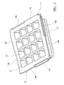
- Figure 1 is a perspective view from above of an insulating member in accordance with this invention;
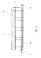
- Figure 2 is a perspective view from below of the insulating member of Figure 1;
- Figure 3 is a side view of the insulating member of Figure 1;
- Figure 4 a plan view of an array of the insulating members of Figure 1;
- Figure 5 is a vertical section through an embodiment of foundation in accordance with this invention;
- Figure 6 is a vertical section through a second embodiment of foundation in accordance with this invention;
- Figure 7 is a side view of an insulating member of an third embodiment of foundation in accordance with this invention; and
- Figure 8 is a side view of an insulating member of an fourth embodiment of foundation in accordance with this invention.
-
- Referring to Figures 1 to 3 of the drawings, there is shown an insulating
member 10 of expanded polystyrene or other light weight moulded plastics material. Themember 10 is approximately one square metre in area and comprises a square flattop wall 11, and dependingside walls 12, which define a hollow under surface of the member. - The hollow under surface of the member is preferably divided by a lattice of
walls 16 into individual voids 17 having an open bottom. The dividingwalls 16 serve to support the top wall of themember 10, so that a person can safely stand or walk on the member during construction of the foundation. Thewalls 16 also enable themember 10 to be cut without affecting its structural integrity and still leaving a peripheral wall, which prevents the concrete from filling the voids 17. - The bottom edge of each
side wall 12 is provided with an outwardly projectingflange 13 which extends fully across the member and is joined at its opposite ends to theflanges 13 ofadjacent side walls 12 respectively. - Each
flange 13 comprises pair oftabs flange 13 towards a point intermediate opposite ends of the flange, where the twotabs tab 14a lies in the same plane as the upper surface of theflange 13, whilst the lower surface of theother tab 14b lies in the same plane as the lower surface of theflange 13. The lower surface of thefirst tab 14a lies in or slightly above the plane of the upper surface of theother tab 14b. - Referring to Figure 4 of the drawings, a plurality of
members 10 can be connected in an array by inter-engaging theirtabs tabs - Referring to Figure 5 of the drawings, to form a foundation in accordance with this invention, it is first necessary to prepare the site. The ground on which the foundation is to be laid is levelled either by cutting the ground away or in-filling. If in-filling is used, it may be necessary to construct piers, having a depth and location which is determined by an engineer. Herbicides and pesticides may be applied to the ground before the foundation is laid and optionally, a damp proof membrane may be provided in the form of a plastic sheet, covering the entire building area.
- A shallow trench is dug around the perimeter of the foundation to be laid, with the depth of the trench being determined by the soil type and the susceptibility of the area to frost. An array of insulating
members 10 is then laid on the original ground level O inside the trench. If necessary, the insulatingmembers 10 around the periphery of the array may be cut to size on site. However, it is envisaged that themembers 10 could pre-cut according to the design of the dwelling being constructed. Shuttering is then set up around the trench and elongate reinforcingcages 20 are laid along each side of the trench and connected end-to-end. Thecages 20 each comprise a pair of upper and lower elongate steel reinforcing rods, which are spaced apart from each other and interconnected by crossmembers extending perpendicular to the axis of the rods. Reinforcingrods 21 are laid along the gaps 23 formed between each row and column of the array of insulatingmembers 10. Therods 21 are preferably supported on supports (not shown). Agrid 22 of reinforcing rods is then laid on top of the insulatingmembers 10 and joined around its periphery to respective sides of thecage 20 extending around the array. Thegrid 22 is preferably mounted onspaces 24, which lift the grid away from the upper surface of the insulatingmembers 10. - After the initial assembly has taken place, concrete is poured into the trench surrounding the foundation to an initial level L. Once the concrete has set, the shuttering can be removed and several courses of
bricks 25 can be laid around the perimeter of the foundation, outwardly of theperipheral cage 20, which has its upper side exposed out of the poured layer of concrete. A layer of insulatingmaterial 26 is then placed against the inner surface of the constructedbrick work 25. - Finally, concrete is poured over the array to cover the reinforcing
grid 22. It will be appreciated that the layer of insulatingmaterial 26 and thebrick work 25 acts as shuttering to contain the poured concrete. Aninner wall 27 can then be constructed around the perimeter of the final poured layer of concrete, against thelayer 26 of insulating material. Optionally, a layer of screed may then be poured to cover the concrete. - Soil is then filled in around the foundation to bring the finished ground level F against the
outer brick work 25. - The interlocked insulating
members 10 form a continuous layer over the ground and thus act as a thermal barrier. Theperipheral cage 20 strengthens theedge beam 29 of concrete and enables multi-storey dwellings and other buildings to be constructed on the foundation, without the risk that the foundation will crack under the applied weight and torsional stresses. The stepped configuration of theedge beam 29 enables the outer course ofbrick work 25 to be constructed from a level L, which is below the finished ground level F. Thus, when the ground is in-filled following construction of the foundation, theperipheral edge beam 29 is hidden from view, thereby greatly improving the aesthetic appearance of the dwelling or other building. Furthermore, surface ground water is unable to penetrate under the edge of the foundation, which is set below ground level. - Referring to Figure 6 of the drawings, there is shown an alternative embodiment of foundation in accordance with this invention and like parts are given like reference numerals. In this embodiment, the foundation is constructed on a
layer 30 ofcourse aggregate 30, the depth of which is dependent upon the soil type. Shuttering is then laid on the upper surface of the aggregate 30 to define the perimeter of the foundation to be laid. If necessary, sheets of insulatingmaterial 31 can be placed against the shuttering and on the ground adjacent thereto. The foundation is then constructed in exactly the same manner as that of Figure 5. The insulating 31 material may act as shuttering to contain the poured concrete. - Referring to Figure 9 of the drawings, in an alternative embodiment the insulating
material 31 comprises an elongate extrusion having a lower flange interconnected along its upper edge to the lower edge of a parallel upper flange by a transverse web. The Z-shape of the extrusion acts a shutter to enable the stepped edge-beam 29 to be cast in a single stage. The extrusion also provides a complete thermal barrier around the foundation. - The foundation of Figure 6 is suited to clay or other heavy soils which expand and contract as the soil gets wet and dries. Also, the aggregate 30 helps to alleviate the effects of frost heave or other soil movements attributable to the soil and ground conditions, for example where in-filling of the ground has occurred as a result of the removal of root systems.
- Referring to Figure 7 of the drawings, there is shown an alternative embodiment of insulating member which is formed of a plastics material by extrusion. Lengths of the extrusion are then cut to form the
individual members 10. - A
groove 70 extends along the bottom edge of the opposed side walls of the member and in-use, adjacent rows or columns of the array of insulating members are fastened together with elongate T-section strips 71, which are also formed of plastics material by extrusion. Thestrips 71 carry oppositely directedflanges 72 which respectively project into thegrooves 70 of adjacent members in the row of the array. Short strips (not shown) are then fitted to the fill gaps left between the adjacent members in the column of the array, or vice-versa if thestrips 71 extend between the columns. - When concrete is poured onto the array, the weight of the concrete bears on the
strips 71 between adjacent rows or columns and thereby prevents the insulating members from floating. - Referring to Figure 8 of the drawings, there is shown an alternative embodiment of insulating member which is similar in construction and which comprises a
flange 80 extending along the bottom edge of the opposed side walls of the member. In use, adjacent rows or columns of the array of insulating members are fastened together with elongate T-section strips 81, which are also formed of plastics material by extrusion. Thestrips 81 carry oppositely directedflanges 82 which respectively engage over theflanges 80 of adjacent members in the row of the array and again prevent the insulating members from floating.
Claims (41)
- A method of forming a foundation, which method comprises providing shuttering at ground level to define the perimeter of the foundation on the surface of the ground, positioning a plurality of insulating members in an array within the shuttering and separated by spacers, providing reinforcing rods resting on top of the insulating members and extending around the periphery of the array, and pouring concrete over and between the insulating members so as to embed the reinforcing rods.
- A method as claimed in claim 1, in which a plurality of reinforcing rods are laid around the periphery of the array.
- A method as claimed in claim 2, in which adjacent ones of said peripheral rods are interconnected at intervals by connecting rods lying substantially perpendicular to the direction in which the reinforcing rods extend.
- A method as claimed in any preceding claim, in which the reinforcing rods resting on top of the insulating members form a grid, the grid being joined around its periphery to the reinforcing rods extending around the periphery of the array.
- A method as claimed in any preceding claim, in which the spaces between adjacent insulating members in the array are substantially covered by spacers formed of an insulating material.
- A method as claimed in claim 5, in which the spacers are provided by laying strips of insulating material along the spaces between adjacent insulating members in the array.
- A method as claimed in claim 5, in which the spacers are formed integrally with the insulating members and are provided by projections on the side walls of the insulating members, the insulating members being laid such that they abut each other.
- A method as claimed in claim 7, in which the projections on the side walls of the insulating members are interlocked with adjacent insulating members in the array.
- A method as claimed in any preceding claim, in which the foundation is laid to extend at least 400mm below the finished ground level surrounding the foundation.
- A method as claimed in any preceding claim, in which the ground is be excavated and filled with a coarse aggregate prior to laying the foundation thereon.
- A method as claimed in any preceding claim, in which the concrete extending around the periphery of the array of insulating members is laid to a depth below the level on which the insulating members are placed.
- A method as claimed in any preceding claim, in which the concrete extending around the periphery of the array of insulating members is laid to provide a peripheral step having an upper surface which is lower than the upper surface of the concrete covering the insulating members.
- A method as claimed in claim 12, in which an outer course of bricks is laid on the step.
- A method as claimed in claim 13, in which the ground is in-filled to meet the peripheral course of bricks.
- A method as claimed in claim 14, in which the ground is laid to a level below upper surface of the concrete covering the insulating members and above the upper surface of the peripheral step.
- A method as claimed in any of claims 12 to 15, in which the concrete is initially pored to a level defining the upper surface of the step.
- A method as claimed in claim 16, in which a course of bricks is then laid on the step, which course of bricks forms the shuttering, into which the concrete that covers the insulating members is poured.
- A method as claimed in claim 16, in which the internal face of the course of bricks is lined with a layer of insulating material prior to pouring the concrete which covers the insulating members.
- A method as claimed in claim 16, in which a second shuttering is erected on the step, the concrete that covers the insulating members then being poured into the second shuttering.
- A method as claimed in any preceding claim, in which the insulating members are 0.5 to 4 square metres in horizontal section.
- A foundation comprising a plurality of insulating members in laid in an array on the surface of the ground and separated by spacers, reinforcing rods resting on top of the insulating members and extending around the periphery of the array, and concrete extending over and between the insulating members and embedding the reinforcing rods.
- A foundation as claimed in claim 21, in which a plurality of reinforcing rods extend around the periphery of the array.
- A foundation as claimed in claim 21, in which adjacent rods are interconnected at intervals by connecting rods lying 5 substantially perpendicular to the direction in which the reinforcing rods extend.
- A foundation as claimed in any of claims 21 to 23, in which the reinforcing rods resting on top of the insulating members form a grid, which is joined around its periphery to the reinforcing rods extending around the periphery of the array.
- A foundation as claimed in any of claims 21 to 24, in which the spaces between adjacent insulating members in the array are substantially covered by spacers formed of an 5 insulating material.
- A foundation as claimed in claim 25, in which the spacers comprise strips of insulating material extending along the spaces between adjacent insulating members in the array.
- A foundation as claimed in claim 25, in which the spacers are formed integrally with the insulating members and are provided by projections on the side walls of the insulating members, the insulating members abutting each other to provide a substantially complete thermal barrier between the upper and lower surface of the foundation.
- A foundation as claimed in claim 27, in which the side walls of the insulating members may be inclined outwardly from their upper surface towards their lower surface to provide said projections.
- A foundation as claimed in claim 27, in which the projections may comprise flanges which extend outwardly from the lower edge of the side walls.
- A foundation as claimed in claims 28 or 29, in which the projections on the side walls of the insulating members are interlocked with adjacent insulating members in the array.
- A foundation as claimed in any of claims 21 to 30, in which the foundation extends at least 400mm below the finished ground level surrounding the foundation.
- A foundation as claimed in any of claims 21 to 31, in which the insulating members are laid on a layer of coarse aggregate.
- A foundation as claimed in any of claims 21 to 32, in which the concrete extending around the periphery of the array of insulating members extends to a depth below the level of the underside of the insulating members.
- A foundation as claimed in any of claims 21 to 33, in which the concrete extending around the periphery of the array of insulating members preferably comprises a peripheral step having an upper surface which is lower than the upper surface of the concrete covering the insulating members.
- A foundation as claimed in claim 34, in which the a course of bricks is laid on the step and contains the concrete that covers the insulating members.
- A foundation as claimed in claim 34, in which the internal face of the course of bricks is lined with a layer of insulating material.
- A foundation as claimed in any of claims 21 to 36, in which reinforcing rods extend between adjacent insulating members in the array.
- An insulating structure for a foundation, comprising a 5 plurality of square or rectangular members of insulating material laid in an array, each member having an upper surface, a lower surface, opposite side walls and opposite end walls, at least one of said side walls and at least one of said end walls carrying projections which respectively abut the respective opposite walls of adjacent members in the array.
- A insulating structure as claimed in claim 38, in which at least one of said side walls and at least one of said end walls are inclined outwardly from the upper surface towards their lower surface to provide said projections.
- A insulating structure as claimed in claim 38, in which the projections comprise flanges which extend outwardly from the lower edge of the respective walls.
- A insulating structure as claimed in any of claims 38 to 40, in which the projections are interlocked with adjacent insulating members in the array.
Applications Claiming Priority (4)
| Application Number | Priority Date | Filing Date | Title |
|---|---|---|---|
| GB0202766A GB0202766D0 (en) | 2002-02-06 | 2002-02-06 | Foundation |
| GB0202766 | 2002-02-06 | ||
| GB0223613 | 2002-10-11 | ||
| GB0223613A GB2385071B (en) | 2002-02-06 | 2002-10-11 | Foundations |
Publications (2)
| Publication Number | Publication Date |
|---|---|
| EP1335073A2 true EP1335073A2 (en) | 2003-08-13 |
| EP1335073A3 EP1335073A3 (en) | 2004-06-09 |
Family
ID=27614806
Family Applications (1)
| Application Number | Title | Priority Date | Filing Date |
|---|---|---|---|
| EP03250659A Withdrawn EP1335073A3 (en) | 2002-02-06 | 2003-02-01 | Foundations |
Country Status (1)
| Country | Link |
|---|---|
| EP (1) | EP1335073A3 (en) |
Cited By (4)
| Publication number | Priority date | Publication date | Assignee | Title |
|---|---|---|---|---|
| WO2005042854A1 (en) * | 2003-11-03 | 2005-05-12 | Damian Kieth Little | Foundations and bases for buildings |
| WO2011135354A3 (en) * | 2010-04-29 | 2012-05-03 | Sig Plc | Method for forming a building foundation, building foundation, system, spacer, connector and insulating block |
| AU2013200496B2 (en) * | 2013-01-31 | 2015-10-01 | Ambe Engineering Pty Ltd | Systems for forming insulated thermal mass concrete slabs |
| WO2020157715A1 (en) * | 2019-02-01 | 2020-08-06 | Ehlers Jan Gerhardus | Floating foundation |
Citations (7)
| Publication number | Priority date | Publication date | Assignee | Title |
|---|---|---|---|---|
| FR1525178A (en) * | 1967-03-28 | 1968-05-17 | New construction process for self-supporting slabs | |
| US3757481A (en) * | 1970-09-18 | 1973-09-11 | J Skinner | Monolithic structural member and systems therefor |
| US4788809A (en) * | 1985-12-24 | 1988-12-06 | Koukourou & Partners Pty. Ltd. | Building foundation |
| US4799348A (en) * | 1984-06-19 | 1989-01-24 | Max Brami | Method and equipment for making a rigid slab enabling to carry a building |
| US5526623A (en) * | 1994-02-19 | 1996-06-18 | Roxbury Limited | Structural beams |
| US5934036A (en) * | 1996-11-01 | 1999-08-10 | Gallagher, Jr.; Daniel P. | Insulated concrete slab assembly |
| AU710541B1 (en) * | 1999-02-17 | 1999-09-23 | Neumann Steel Pty Limited | Monolithic concrete raft slabs |
-
2003
- 2003-02-01 EP EP03250659A patent/EP1335073A3/en not_active Withdrawn
Patent Citations (7)
| Publication number | Priority date | Publication date | Assignee | Title |
|---|---|---|---|---|
| FR1525178A (en) * | 1967-03-28 | 1968-05-17 | New construction process for self-supporting slabs | |
| US3757481A (en) * | 1970-09-18 | 1973-09-11 | J Skinner | Monolithic structural member and systems therefor |
| US4799348A (en) * | 1984-06-19 | 1989-01-24 | Max Brami | Method and equipment for making a rigid slab enabling to carry a building |
| US4788809A (en) * | 1985-12-24 | 1988-12-06 | Koukourou & Partners Pty. Ltd. | Building foundation |
| US5526623A (en) * | 1994-02-19 | 1996-06-18 | Roxbury Limited | Structural beams |
| US5934036A (en) * | 1996-11-01 | 1999-08-10 | Gallagher, Jr.; Daniel P. | Insulated concrete slab assembly |
| AU710541B1 (en) * | 1999-02-17 | 1999-09-23 | Neumann Steel Pty Limited | Monolithic concrete raft slabs |
Cited By (4)
| Publication number | Priority date | Publication date | Assignee | Title |
|---|---|---|---|---|
| WO2005042854A1 (en) * | 2003-11-03 | 2005-05-12 | Damian Kieth Little | Foundations and bases for buildings |
| WO2011135354A3 (en) * | 2010-04-29 | 2012-05-03 | Sig Plc | Method for forming a building foundation, building foundation, system, spacer, connector and insulating block |
| AU2013200496B2 (en) * | 2013-01-31 | 2015-10-01 | Ambe Engineering Pty Ltd | Systems for forming insulated thermal mass concrete slabs |
| WO2020157715A1 (en) * | 2019-02-01 | 2020-08-06 | Ehlers Jan Gerhardus | Floating foundation |
Also Published As
| Publication number | Publication date |
|---|---|
| EP1335073A3 (en) | 2004-06-09 |
Similar Documents
| Publication | Publication Date | Title |
|---|---|---|
| US5039256A (en) | Pinned foundation system | |
| US6434900B1 (en) | Prefabricated concrete wall system | |
| US5400563A (en) | Combination column and panel barrier system and method of construction | |
| US7076925B2 (en) | Integrated footings | |
| CA2420991C (en) | Integrated footings | |
| EP0528578A1 (en) | Improvements in or relating to supports for building structures | |
| US8011158B1 (en) | Footing for support of structure such as building | |
| GB2240350A (en) | Forming foundation beams | |
| US7073304B2 (en) | Corner building block, system and method | |
| GB2385071A (en) | Building foundation with insulating members | |
| EP1335073A2 (en) | Foundations | |
| RU69094U1 (en) | SPATIAL REINFORCED CONCRETE FOUNDATION PLATFORM IN THE ASSEMBLY AND COMBINED-MONOLITHIC OPTIONS FOR LOW-STOREY CONSTRUCTION IN DIFFICULT GROUND CONDITIONS AND SEISMIC | |
| RU55388U1 (en) | SPATIAL REINFORCED CONCRETE FOUNDATION PLATFORM FOR SMALL-STOREY BUILDINGS FOR CONSTRUCTION IN SPECIAL GROUND CONDITIONS AND SEISMICITY IN ASSEMBLY AND MONOLITHIC OPTIONS | |
| RU2379424C1 (en) | Method for erection of foundation slab of framed structure | |
| KR20160006305A (en) | Retaining wall block and the construction method | |
| US5558470A (en) | System and method for adjustably anchoring traffic barriers and wall facing panels to the soldier beams of a wall | |
| RU2376428C1 (en) | Multi-storied building and method of erection on slopes or cliffs | |
| RU59650U1 (en) | SEISMIC RESISTANT SMALL BUILDING, STRUCTURE | |
| US9611615B2 (en) | Apparatus and method for stabilizing a slab foundation | |
| JPH0324525B2 (en) | ||
| KR100793684B1 (en) | Assemble type wall structure and constructing method thereof | |
| WO2005042854A1 (en) | Foundations and bases for buildings | |
| KR20060134651A (en) | Landscape facilities and constuction method thereof | |
| AU2014252765A1 (en) | Slab construction | |
| JPS6011175Y2 (en) | Prefabricated retaining wall |
Legal Events
| Date | Code | Title | Description |
|---|---|---|---|
| PUAI | Public reference made under article 153(3) epc to a published international application that has entered the european phase |
Free format text: ORIGINAL CODE: 0009012 |
|
| AK | Designated contracting states |
Designated state(s): AT BE BG CH CY CZ DE DK EE ES FI FR GB GR HU IE IT LI LU MC NL PT SE SI SK TR |
|
| AX | Request for extension of the european patent |
Extension state: AL LT LV MK RO |
|
| PUAL | Search report despatched |
Free format text: ORIGINAL CODE: 0009013 |
|
| AK | Designated contracting states |
Kind code of ref document: A3 Designated state(s): AT BE BG CH CY CZ DE DK EE ES FI FR GB GR HU IE IT LI LU MC NL PT SE SI SK TR |
|
| AX | Request for extension of the european patent |
Extension state: AL LT LV MK RO |
|
| 17P | Request for examination filed |
Effective date: 20040916 |
|
| 17Q | First examination report despatched |
Effective date: 20050117 |
|
| AKX | Designation fees paid |
Designated state(s): AT BE BG CH CY CZ DE DK EE ES FI FR GB GR HU IE IT LI LU MC NL PT SE SI SK TR |
|
| 17Q | First examination report despatched |
Effective date: 20050117 |
|
| STAA | Information on the status of an ep patent application or granted ep patent |
Free format text: STATUS: THE APPLICATION IS DEEMED TO BE WITHDRAWN |
|
| 18D | Application deemed to be withdrawn |
Effective date: 20060901 |