EP1334946A1 - Innenbackenbremse für einen Aufzugsantrieb - Google Patents
Innenbackenbremse für einen Aufzugsantrieb Download PDFInfo
- Publication number
- EP1334946A1 EP1334946A1 EP03002266A EP03002266A EP1334946A1 EP 1334946 A1 EP1334946 A1 EP 1334946A1 EP 03002266 A EP03002266 A EP 03002266A EP 03002266 A EP03002266 A EP 03002266A EP 1334946 A1 EP1334946 A1 EP 1334946A1
- Authority
- EP
- European Patent Office
- Prior art keywords
- brake
- actuating
- shoe
- shoes
- brake shoes
- Prior art date
- Legal status (The legal status is an assumption and is not a legal conclusion. Google has not performed a legal analysis and makes no representation as to the accuracy of the status listed.)
- Granted
Links
- 238000005096 rolling process Methods 0.000 claims description 6
- 230000006835 compression Effects 0.000 description 12
- 238000007906 compression Methods 0.000 description 12
- 238000009423 ventilation Methods 0.000 description 6
- 230000000694 effects Effects 0.000 description 2
- 230000002860 competitive effect Effects 0.000 description 1
- 238000010276 construction Methods 0.000 description 1
- 230000001419 dependent effect Effects 0.000 description 1
- 238000013461 design Methods 0.000 description 1
- 238000011161 development Methods 0.000 description 1
- 230000018109 developmental process Effects 0.000 description 1
- 238000012423 maintenance Methods 0.000 description 1
- 238000013022 venting Methods 0.000 description 1
Images



Classifications
-
- F—MECHANICAL ENGINEERING; LIGHTING; HEATING; WEAPONS; BLASTING
- F16—ENGINEERING ELEMENTS AND UNITS; GENERAL MEASURES FOR PRODUCING AND MAINTAINING EFFECTIVE FUNCTIONING OF MACHINES OR INSTALLATIONS; THERMAL INSULATION IN GENERAL
- F16D—COUPLINGS FOR TRANSMITTING ROTATION; CLUTCHES; BRAKES
- F16D65/00—Parts or details
- F16D65/02—Braking members; Mounting thereof
- F16D65/04—Bands, shoes or pads; Pivots or supporting members therefor
- F16D65/08—Bands, shoes or pads; Pivots or supporting members therefor for internally-engaging brakes
- F16D65/09—Pivots or supporting members therefor
-
- B—PERFORMING OPERATIONS; TRANSPORTING
- B66—HOISTING; LIFTING; HAULING
- B66D—CAPSTANS; WINCHES; TACKLES, e.g. PULLEY BLOCKS; HOISTS
- B66D5/00—Braking or detent devices characterised by application to lifting or hoisting gear, e.g. for controlling the lowering of loads
- B66D5/02—Crane, lift hoist, or winch brakes operating on drums, barrels, or ropes
- B66D5/06—Crane, lift hoist, or winch brakes operating on drums, barrels, or ropes with radial effect
- B66D5/08—Crane, lift hoist, or winch brakes operating on drums, barrels, or ropes with radial effect embodying blocks or shoes
-
- B—PERFORMING OPERATIONS; TRANSPORTING
- B66—HOISTING; LIFTING; HAULING
- B66D—CAPSTANS; WINCHES; TACKLES, e.g. PULLEY BLOCKS; HOISTS
- B66D5/00—Braking or detent devices characterised by application to lifting or hoisting gear, e.g. for controlling the lowering of loads
- B66D5/02—Crane, lift hoist, or winch brakes operating on drums, barrels, or ropes
- B66D5/24—Operating devices
- B66D5/30—Operating devices electrical
-
- F—MECHANICAL ENGINEERING; LIGHTING; HEATING; WEAPONS; BLASTING
- F16—ENGINEERING ELEMENTS AND UNITS; GENERAL MEASURES FOR PRODUCING AND MAINTAINING EFFECTIVE FUNCTIONING OF MACHINES OR INSTALLATIONS; THERMAL INSULATION IN GENERAL
- F16D—COUPLINGS FOR TRANSMITTING ROTATION; CLUTCHES; BRAKES
- F16D51/00—Brakes with outwardly-movable braking members co-operating with the inner surface of a drum or the like
- F16D51/16—Brakes with outwardly-movable braking members co-operating with the inner surface of a drum or the like shaped as brake-shoes pivoted on a fixed or nearly-fixed axis
- F16D51/32—Brakes with outwardly-movable braking members co-operating with the inner surface of a drum or the like shaped as brake-shoes pivoted on a fixed or nearly-fixed axis with three or more brake shoes
- F16D51/34—Brakes with outwardly-movable braking members co-operating with the inner surface of a drum or the like shaped as brake-shoes pivoted on a fixed or nearly-fixed axis with three or more brake shoes extending in opposite directions from their pivots
-
- F—MECHANICAL ENGINEERING; LIGHTING; HEATING; WEAPONS; BLASTING
- F16—ENGINEERING ELEMENTS AND UNITS; GENERAL MEASURES FOR PRODUCING AND MAINTAINING EFFECTIVE FUNCTIONING OF MACHINES OR INSTALLATIONS; THERMAL INSULATION IN GENERAL
- F16D—COUPLINGS FOR TRANSMITTING ROTATION; CLUTCHES; BRAKES
- F16D65/00—Parts or details
- F16D65/14—Actuating mechanisms for brakes; Means for initiating operation at a predetermined position
- F16D65/16—Actuating mechanisms for brakes; Means for initiating operation at a predetermined position arranged in or on the brake
- F16D65/22—Actuating mechanisms for brakes; Means for initiating operation at a predetermined position arranged in or on the brake adapted for pressing members apart, e.g. for drum brakes
-
- F—MECHANICAL ENGINEERING; LIGHTING; HEATING; WEAPONS; BLASTING
- F16—ENGINEERING ELEMENTS AND UNITS; GENERAL MEASURES FOR PRODUCING AND MAINTAINING EFFECTIVE FUNCTIONING OF MACHINES OR INSTALLATIONS; THERMAL INSULATION IN GENERAL
- F16D—COUPLINGS FOR TRANSMITTING ROTATION; CLUTCHES; BRAKES
- F16D2121/00—Type of actuator operation force
- F16D2121/18—Electric or magnetic
- F16D2121/20—Electric or magnetic using electromagnets
- F16D2121/22—Electric or magnetic using electromagnets for releasing a normally applied brake
Definitions
- the invention relates to an inner shoe brake for one Elevator drive with more than two brake shoes, which means Compression springs apply a braking force to one Generate brake drum and which can be released by actuators.
- a disadvantage of the known device is the complex Mechanics of a brake unit. Inner shoe brakes with one such complicated brake mechanics are hardly competitive. In addition, the disc springs and the Actuator via several actuating levers on the brake shoe, what higher spring forces or actuator forces required.
- the invention seeks to remedy this.
- the invention as characterized in claim 1 solves the problem to avoid the disadvantages of the known device and an inner shoe brake with more than two brake shoes create that works reliably despite its simple structure.
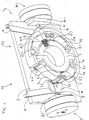
- Fig. 1 shows a spatial representation of a Inner shoe brake 1 according to the invention consisting of a Housing plate 2, a housing ring 3, a brake drum 4th and from two identical brake halves 5.1.5.2.
- the brake drum 4 can be part of a Be a traction sheave.
- the left brake half 5.1 has one upper brake shoe 6 and a lower brake shoe 7.
- the on an upper brake shoe 6.1, upper brake shoe 6 has an actuating roller 6.2 at the free end and will by means of a compression spring 6.3 supported on the housing ring 3 pressed against the brake drum 4.
- the upper brake shoe 6 is shown in section, which is why the brake pad 6.4 in Fig. 1 is not apparent.
- the cut also runs through the roller axis 6.5, on which the actuating roller 6.2 is arranged.
- the lower brake shoe 7 is a mirror image built up to the upper brake shoe 6.
- the parts of the lower Brake shoes are provided with the following reference numbers: Jaw bearing 7.1, actuating roller 7.2, compression spring 7.3, Brake pad 7.4 and roller axle 7.5.
- the free ends of the Brake shoes 6.7 are adjacent.
- An actuator 8 in is provided for venting the brake shoe pair 6, 7 in the form of a brake magnet.
- the one with the actuator base 8.1 connected to the housing plate 2 Actuator 8 acts on a by means of a push rod 9 Actuating fork 10 on which the actuating rollers 6.2.7.2 rolling against the spring force of the compression springs 6.3.7.3 are applied.
- a brake lever 11 is used manual ventilation of the brake shoes 6.7.
- the right brake half 5.2 is a mirror image of the left Brake half 5.1 built.
- the parts of the right Brake half 5.2 are provided with the following reference symbols: Upper brake shoe 12 with shoe bearing 12.1, actuating roller 12.2, compression spring 12.3, brake pad 12.4 and roller axle 12.5.
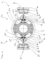
- Fig. 2 shows a top view of the inner shoe brake 1 without Brake drum 4. Visible are rotatable on the housing ring 3 arranged upper brake shoes 6.12 and the actuators 8.14 with the push rods 9.15 and the actuating forks 10.16 for brake ventilation.
- the section along the line A-A is in Fig. 3 and the section along the line B-B is in Fig. 4th shown.
- Fig. 3 shows a section through the brake shoes 6,7,12,13 and by the compression springs 6.3,7.3,12.3,13.3.
- the Compression springs 6.3,7.3,12.3,13.3 are in one end Recesses 6.6,7.6,12.6,13.6 of the housing ring 3 stored and at the other end dive into recesses 6.7,7.7,12.7,13.7 the brake shoes 6,7,12,13.
- the compression springs 6.3,7.3,12.3,13.3 press the brake shoes 6,7,12,13 against the brake drum 4, wherein between the brake drum 4 and the brake pads 6.4,7.4,12.4,13.4 generates the braking forces become.
- Fig. 4 shows a section through the actuators 8,14 Actuating forks 10.16 and the actuating rollers 6.2,7.2,12.2,13.2. Brake actuators 8,14 intended.
- the brake magnet 8 of the left half of the brake 5.1 consists of an anchor plate 8.2 and one on the actuator base 8.1 arranged magnetic coil 8.3.
- the anchor plate 8.2 is connected to the push rod 9, which the movement of the Anchor plate 8.2 transfers to the actuating fork 10.
- On the actuating fork 10 are each on the actuating roller side Actuating roller 6.2.7.2 a rolling slope 10.1, 10.2 intended. Roll as the operating fork 10 advances the actuating rollers 6.2.7.2 on the rolling slopes 10.1, 10.2, with the brake shoes 6.7 against the Compression springs 6.3,7.3 are pressed.
- the brake magnet 14 of the right brake half 5.2 consists of an anchor plate 14.2 and one on the actuator base 14.1 arranged magnetic coil 14.3.
- the anchor plate 14.2 is with the push rod 15 connected to the movement of the Anchor plate 14.2 transfers to the operating fork 16.
- On the actuating fork 16 are each on the actuating roller side Actuating roller 12.2, 13.2 a rolling slope 16.1, 16.2 intended. Roll as the operating fork 16 advances the actuating rollers 12.2,13.2 on the rolling slopes 16.1,16.2, the brake shoes 12,13 against the Compression springs 12.3,13.3 are pressed.
- each brake half 5.1.5.2 instead of one Brake shoe pair several brake shoe pairs can be provided.
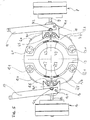
- FIG. 5 shows a rear view of the inner shoe brake 1 Fig. 5 can be seen how the brake levers 11,17 manual ventilation of the inner shoe brake 1 on the Act on actuating forks 10.16.
- the brake lever 11 is on an axis of rotation 11.1 arranged on the housing plate 2 rotatably arranged and has a semicircular recess 11.2, in which a bolt 10.1 of the actuating fork 10 fits.
- the brake lever 17 is on one on the housing plate 2 arranged axis of rotation 17.1 rotatably arranged and has a semicircular recess 17.2 into which a bolt 16.1 the operating fork 16 fits.
- the brake lever 17 is in the Rest position and the brake lever 11 is in the Working position or shown with the brake released.
- Fig. 6 shows an actuator for manual Brake shoe ventilation 6,7,12,13.
- the brake levers 11, 17 for example from Maintenance personnel can be operated manually.
- the soul 21 of the Bowden cable 20 is with the free end of one Brake lever 17 connected and the jacket 22 of the Bowden cable 20 is with the free end of the other brake lever 11 connected.
- a release lever 23 in Arrow direction P1 becomes a tensile force in the soul 21 built up.
- On the principle of action reaction the two brake levers 11, 17 in the direction of arrow P3 or P2 moves and the brake shoes 6,7,12,13 released.
Landscapes
- Engineering & Computer Science (AREA)
- General Engineering & Computer Science (AREA)
- Mechanical Engineering (AREA)
- Braking Arrangements (AREA)
- Cage And Drive Apparatuses For Elevators (AREA)
Abstract
Description
Claims (4)
- Innenbackenbremse für einen Aufzugsantrieb mit mehr als zwei Bremsbacken (6,7,12,13), die mittels Druckfedern (6.3, 7.3, 12.3, 13.3) beaufschlagt eine Bremskraft an einer Bremstrommel (4) erzeugen und die mittels Aktoren (8,14) lüftbar sind,
dadurch gekennzeichnet, dass zur Lüftung eines Bremsbackenpaares (6,7,12,13) ein Aktor (8,14) vorgesehen ist. - Innenbackenbremse nach Anspruch 1,
dadurch gekennzeichnet, dass die Bremsbacken (6,7,12,13) eines Bremsbackenpaares an Backenlagern (6.1, 7.1, 12.1, 13.1) drehbar gelagert sind und die freien Enden der Bremsbacken (6,7,12,13) benachbart sind. - Innenbackenbremse nach den Ansprüchen 1 oder 2,
dadurch gekennzeichnet, dass an den freien Enden der Bremsbacken (6,7,12,13) Betätigungsrollen (6.2,7.2,12.2,13.2) angeordnet sind, die paarweise mittels einer Betätigungsgabel (10,16) der Aktoren (8,14) beaufschlagbar sind. - Innenbackenbremse nach Anspruch 3,
dadurch gekennzeichnet, dass die Betätigungsgabel (10,16) je Batätigungsrolle (6.2,7.2,12.2,13.2) eine Abrollschräge (10.1,10.2,16.1,16.2) aufweist, an denen die Batätigungsrollen (6.2,7.2,12.2,13.2) beaufschlagbar sind.
Priority Applications (2)
| Application Number | Priority Date | Filing Date | Title |
|---|---|---|---|
| ES03002266T ES2304474T3 (es) | 2002-02-08 | 2003-02-01 | Freno de zapatas interiores para un accionamiento de ascensor. |
| EP03002266A EP1334946B1 (de) | 2002-02-08 | 2003-02-01 | Innenbackenbremse für einen Aufzugsantrieb |
Applications Claiming Priority (3)
| Application Number | Priority Date | Filing Date | Title |
|---|---|---|---|
| EP02405088 | 2002-02-08 | ||
| EP02405088 | 2002-02-08 | ||
| EP03002266A EP1334946B1 (de) | 2002-02-08 | 2003-02-01 | Innenbackenbremse für einen Aufzugsantrieb |
Publications (2)
| Publication Number | Publication Date |
|---|---|
| EP1334946A1 true EP1334946A1 (de) | 2003-08-13 |
| EP1334946B1 EP1334946B1 (de) | 2008-04-02 |
Family
ID=39273398
Family Applications (1)
| Application Number | Title | Priority Date | Filing Date |
|---|---|---|---|
| EP03002266A Expired - Lifetime EP1334946B1 (de) | 2002-02-08 | 2003-02-01 | Innenbackenbremse für einen Aufzugsantrieb |
Country Status (5)
| Country | Link |
|---|---|
| EP (1) | EP1334946B1 (de) |
| AT (1) | ATE391109T1 (de) |
| DE (1) | DE50309508D1 (de) |
| DK (1) | DK1334946T3 (de) |
| ES (1) | ES2304474T3 (de) |
Cited By (3)
| Publication number | Priority date | Publication date | Assignee | Title |
|---|---|---|---|---|
| ES2324969A1 (es) * | 2007-01-22 | 2009-08-20 | Luis Alzola Elizondo | Dispositivo impulsor electromagnetico de mecanismos. |
| CN108425964A (zh) * | 2018-05-29 | 2018-08-21 | 江苏工程职业技术学院 | 一种新能源电动车的平衡制动系统 |
| US10442659B2 (en) | 2015-06-29 | 2019-10-15 | Otis Elevator Company | Electromagnetic brake system for elevator application |
Citations (5)
| Publication number | Priority date | Publication date | Assignee | Title |
|---|---|---|---|---|
| US2407487A (en) * | 1944-05-29 | 1946-09-10 | Kelsey Hayes Wheel Co | Brake |
| FR1545153A (fr) * | 1966-11-23 | 1968-11-08 | Perrot Bremse Gmbh Deutsche | Frein à sabots intérieurs, comportant au moins deux paires de mâchoires disposées côte à côte |
| US5255763A (en) * | 1992-07-08 | 1993-10-26 | Eaton Corporation | Brake cam roller follower bracket |
| EP0933325A1 (de) * | 1998-01-23 | 1999-08-04 | Thyssen Aufzüge Gmbh | Fahrtreppe mit Betriebsbremse |
| DE19846671A1 (de) * | 1998-10-09 | 2000-04-13 | Erhard Mueller | Treibscheibenbremse mit erhöhter Redundanz |
-
2003
- 2003-02-01 DK DK03002266T patent/DK1334946T3/da active
- 2003-02-01 ES ES03002266T patent/ES2304474T3/es not_active Expired - Lifetime
- 2003-02-01 EP EP03002266A patent/EP1334946B1/de not_active Expired - Lifetime
- 2003-02-01 AT AT03002266T patent/ATE391109T1/de active
- 2003-02-01 DE DE50309508T patent/DE50309508D1/de not_active Expired - Lifetime
Patent Citations (5)
| Publication number | Priority date | Publication date | Assignee | Title |
|---|---|---|---|---|
| US2407487A (en) * | 1944-05-29 | 1946-09-10 | Kelsey Hayes Wheel Co | Brake |
| FR1545153A (fr) * | 1966-11-23 | 1968-11-08 | Perrot Bremse Gmbh Deutsche | Frein à sabots intérieurs, comportant au moins deux paires de mâchoires disposées côte à côte |
| US5255763A (en) * | 1992-07-08 | 1993-10-26 | Eaton Corporation | Brake cam roller follower bracket |
| EP0933325A1 (de) * | 1998-01-23 | 1999-08-04 | Thyssen Aufzüge Gmbh | Fahrtreppe mit Betriebsbremse |
| DE19846671A1 (de) * | 1998-10-09 | 2000-04-13 | Erhard Mueller | Treibscheibenbremse mit erhöhter Redundanz |
Cited By (4)
| Publication number | Priority date | Publication date | Assignee | Title |
|---|---|---|---|---|
| ES2324969A1 (es) * | 2007-01-22 | 2009-08-20 | Luis Alzola Elizondo | Dispositivo impulsor electromagnetico de mecanismos. |
| ES2324969B1 (es) * | 2007-01-22 | 2010-06-01 | Luis Alzola Elizondo | Dispositivo impulsor electromagnetico de mecanismos. |
| US10442659B2 (en) | 2015-06-29 | 2019-10-15 | Otis Elevator Company | Electromagnetic brake system for elevator application |
| CN108425964A (zh) * | 2018-05-29 | 2018-08-21 | 江苏工程职业技术学院 | 一种新能源电动车的平衡制动系统 |
Also Published As
| Publication number | Publication date |
|---|---|
| DK1334946T3 (da) | 2008-06-23 |
| ATE391109T1 (de) | 2008-04-15 |
| DE50309508D1 (de) | 2008-05-15 |
| EP1334946B1 (de) | 2008-04-02 |
| ES2304474T3 (es) | 2008-10-16 |
Similar Documents
| Publication | Publication Date | Title |
|---|---|---|
| CH633084A5 (de) | Backenbremse. | |
| DE1455871A1 (de) | Bremsvorrichtung | |
| EP1941179B1 (de) | Scheibenbremse mit elektromotorischem aktuator in selbstverstärkender bauart | |
| EP2121359B2 (de) | Vorrichtung zur gesteuerten betätigung eines schaltorgans eines ventils | |
| DE10212879A1 (de) | Betätigungsmechanismus für eine Feststellbremse | |
| EP0738643B1 (de) | Bremszangeneinheit für Scheibenbremsen von Fahrzeugen, insbesondere Schienenfahrzeugen | |
| EP0664767B1 (de) | Flachbauende hebebühne | |
| EP1334946B1 (de) | Innenbackenbremse für einen Aufzugsantrieb | |
| EP2102524A2 (de) | Scheibenbremse mit elektromotorischen aktuator in selbstverstärkender bauart | |
| DE2513870B2 (de) | Betaetigungsvorrichtung fuer eine fahrzeugbremse | |
| DE1480663A1 (de) | Lenk- und Antriebseinheit fuer Flurfoerderfahrzeuge | |
| DE102005053835B4 (de) | Kompakte Bremszange mit hoher und variabler Kraftübersetzung | |
| DE102011111087A1 (de) | Pedalvorrichtung, Kupplungssystem und Kraftfahrzeug | |
| EP0992701B1 (de) | Trommelbremse für ein Kraftfahrzeug | |
| EP1419320A1 (de) | Vorrichtung zum betätigen eines seilzugs | |
| DE19846671A1 (de) | Treibscheibenbremse mit erhöhter Redundanz | |
| DE10004058B4 (de) | Bremsvorrichtung | |
| EP0666207B1 (de) | Elektromechanische Zuspannvorrichtung für Reibungsbremsen | |
| DE2823843C2 (de) | Bremseinrichtung für Schienenfahrzeuge | |
| DE4202635A1 (de) | Bremszange fuer schreibenbremsen von schienenfahrzeugen | |
| DE810765C (de) | Bremse, insbesondere fuer Schienenfahrzeuge | |
| WO2006094420A1 (de) | Backenbremse für einen aufzugsantrieb | |
| DE236301C (de) | ||
| DE2101768C3 (de) | Handbremsbetätigungseinrichhing an Baufahrzeugen, insbesondere Vibrationswalzen | |
| DE102024210856A1 (de) | Elektromechanische Bremse mit Motorkontakten in Ecken des Motorgehäuses |
Legal Events
| Date | Code | Title | Description |
|---|---|---|---|
| PUAI | Public reference made under article 153(3) epc to a published international application that has entered the european phase |
Free format text: ORIGINAL CODE: 0009012 |
|
| AK | Designated contracting states |
Designated state(s): AT BE BG CH CY CZ DE DK EE ES FI FR GB GR HU IE IT LI LU MC NL PT SE SI SK TR |
|
| AX | Request for extension of the european patent |
Extension state: AL LT LV MK RO |
|
| 17P | Request for examination filed |
Effective date: 20040129 |
|
| AKX | Designation fees paid |
Designated state(s): AT BE BG CH CY CZ DE DK EE ES FI FR GB GR HU IE IT LI LU MC NL PT SE SI SK TR |
|
| 17Q | First examination report despatched |
Effective date: 20040722 |
|
| GRAP | Despatch of communication of intention to grant a patent |
Free format text: ORIGINAL CODE: EPIDOSNIGR1 |
|
| GRAS | Grant fee paid |
Free format text: ORIGINAL CODE: EPIDOSNIGR3 |
|
| GRAA | (expected) grant |
Free format text: ORIGINAL CODE: 0009210 |
|
| AK | Designated contracting states |
Kind code of ref document: B1 Designated state(s): AT BE BG CH CY CZ DE DK EE ES FI FR GB GR HU IE IT LI LU MC NL PT SE SI SK TR |
|
| REG | Reference to a national code |
Ref country code: GB Ref legal event code: FG4D Free format text: NOT ENGLISH |
|
| REG | Reference to a national code |
Ref country code: CH Ref legal event code: EP Ref country code: IE Ref legal event code: FG4D Free format text: LANGUAGE OF EP DOCUMENT: GERMAN |
|
| REF | Corresponds to: |
Ref document number: 50309508 Country of ref document: DE Date of ref document: 20080515 Kind code of ref document: P |
|
| REG | Reference to a national code |
Ref country code: DK Ref legal event code: T3 |
|
| REG | Reference to a national code |
Ref country code: SE Ref legal event code: TRGR |
|
| ET | Fr: translation filed | ||
| PG25 | Lapsed in a contracting state [announced via postgrant information from national office to epo] |
Ref country code: SI Free format text: LAPSE BECAUSE OF FAILURE TO SUBMIT A TRANSLATION OF THE DESCRIPTION OR TO PAY THE FEE WITHIN THE PRESCRIBED TIME-LIMIT Effective date: 20080402 |
|
| REG | Reference to a national code |
Ref country code: ES Ref legal event code: FG2A Ref document number: 2304474 Country of ref document: ES Kind code of ref document: T3 |
|
| REG | Reference to a national code |
Ref country code: IE Ref legal event code: FD4D |
|
| PG25 | Lapsed in a contracting state [announced via postgrant information from national office to epo] |
Ref country code: BG Free format text: LAPSE BECAUSE OF FAILURE TO SUBMIT A TRANSLATION OF THE DESCRIPTION OR TO PAY THE FEE WITHIN THE PRESCRIBED TIME-LIMIT Effective date: 20080702 Ref country code: PT Free format text: LAPSE BECAUSE OF FAILURE TO SUBMIT A TRANSLATION OF THE DESCRIPTION OR TO PAY THE FEE WITHIN THE PRESCRIBED TIME-LIMIT Effective date: 20080902 |
|
| PG25 | Lapsed in a contracting state [announced via postgrant information from national office to epo] |
Ref country code: IE Free format text: LAPSE BECAUSE OF FAILURE TO SUBMIT A TRANSLATION OF THE DESCRIPTION OR TO PAY THE FEE WITHIN THE PRESCRIBED TIME-LIMIT Effective date: 20080402 |
|
| PLBE | No opposition filed within time limit |
Free format text: ORIGINAL CODE: 0009261 |
|
| STAA | Information on the status of an ep patent application or granted ep patent |
Free format text: STATUS: NO OPPOSITION FILED WITHIN TIME LIMIT |
|
| PG25 | Lapsed in a contracting state [announced via postgrant information from national office to epo] |
Ref country code: SK Free format text: LAPSE BECAUSE OF FAILURE TO SUBMIT A TRANSLATION OF THE DESCRIPTION OR TO PAY THE FEE WITHIN THE PRESCRIBED TIME-LIMIT Effective date: 20080402 |
|
| 26N | No opposition filed |
Effective date: 20090106 |
|
| PG25 | Lapsed in a contracting state [announced via postgrant information from national office to epo] |
Ref country code: EE Free format text: LAPSE BECAUSE OF FAILURE TO SUBMIT A TRANSLATION OF THE DESCRIPTION OR TO PAY THE FEE WITHIN THE PRESCRIBED TIME-LIMIT Effective date: 20080402 |
|
| PG25 | Lapsed in a contracting state [announced via postgrant information from national office to epo] |
Ref country code: MC Free format text: LAPSE BECAUSE OF NON-PAYMENT OF DUE FEES Effective date: 20090228 Ref country code: CY Free format text: LAPSE BECAUSE OF FAILURE TO SUBMIT A TRANSLATION OF THE DESCRIPTION OR TO PAY THE FEE WITHIN THE PRESCRIBED TIME-LIMIT Effective date: 20080402 |
|
| PG25 | Lapsed in a contracting state [announced via postgrant information from national office to epo] |
Ref country code: GR Free format text: LAPSE BECAUSE OF FAILURE TO SUBMIT A TRANSLATION OF THE DESCRIPTION OR TO PAY THE FEE WITHIN THE PRESCRIBED TIME-LIMIT Effective date: 20080703 |
|
| PG25 | Lapsed in a contracting state [announced via postgrant information from national office to epo] |
Ref country code: LU Free format text: LAPSE BECAUSE OF NON-PAYMENT OF DUE FEES Effective date: 20090201 |
|
| PGFP | Annual fee paid to national office [announced via postgrant information from national office to epo] |
Ref country code: DK Payment date: 20110210 Year of fee payment: 9 |
|
| PGFP | Annual fee paid to national office [announced via postgrant information from national office to epo] |
Ref country code: CZ Payment date: 20110128 Year of fee payment: 9 Ref country code: AT Payment date: 20110214 Year of fee payment: 9 Ref country code: DE Payment date: 20110218 Year of fee payment: 9 Ref country code: SE Payment date: 20110214 Year of fee payment: 9 Ref country code: NL Payment date: 20110216 Year of fee payment: 9 Ref country code: FI Payment date: 20110214 Year of fee payment: 9 Ref country code: FR Payment date: 20110302 Year of fee payment: 9 Ref country code: IT Payment date: 20110219 Year of fee payment: 9 |
|
| PG25 | Lapsed in a contracting state [announced via postgrant information from national office to epo] |
Ref country code: HU Free format text: LAPSE BECAUSE OF FAILURE TO SUBMIT A TRANSLATION OF THE DESCRIPTION OR TO PAY THE FEE WITHIN THE PRESCRIBED TIME-LIMIT Effective date: 20081003 |
|
| PGFP | Annual fee paid to national office [announced via postgrant information from national office to epo] |
Ref country code: ES Payment date: 20110222 Year of fee payment: 9 Ref country code: CH Payment date: 20110516 Year of fee payment: 9 Ref country code: BE Payment date: 20110211 Year of fee payment: 9 Ref country code: GB Payment date: 20110217 Year of fee payment: 9 |
|
| PG25 | Lapsed in a contracting state [announced via postgrant information from national office to epo] |
Ref country code: TR Free format text: LAPSE BECAUSE OF FAILURE TO SUBMIT A TRANSLATION OF THE DESCRIPTION OR TO PAY THE FEE WITHIN THE PRESCRIBED TIME-LIMIT Effective date: 20080402 |
|
| BERE | Be: lapsed |
Owner name: INVENTIO A.G. Effective date: 20120228 |
|
| REG | Reference to a national code |
Ref country code: NL Ref legal event code: V1 Effective date: 20120901 |
|
| REG | Reference to a national code |
Ref country code: CH Ref legal event code: PL |
|
| GBPC | Gb: european patent ceased through non-payment of renewal fee |
Effective date: 20120201 |
|
| PG25 | Lapsed in a contracting state [announced via postgrant information from national office to epo] |
Ref country code: CH Free format text: LAPSE BECAUSE OF NON-PAYMENT OF DUE FEES Effective date: 20120229 Ref country code: SE Free format text: LAPSE BECAUSE OF NON-PAYMENT OF DUE FEES Effective date: 20120202 Ref country code: FI Free format text: LAPSE BECAUSE OF NON-PAYMENT OF DUE FEES Effective date: 20120201 Ref country code: CZ Free format text: LAPSE BECAUSE OF NON-PAYMENT OF DUE FEES Effective date: 20120201 Ref country code: LI Free format text: LAPSE BECAUSE OF NON-PAYMENT OF DUE FEES Effective date: 20120229 |
|
| REG | Reference to a national code |
Ref country code: DK Ref legal event code: EBP |
|
| REG | Reference to a national code |
Ref country code: FR Ref legal event code: ST Effective date: 20121031 |
|
| PG25 | Lapsed in a contracting state [announced via postgrant information from national office to epo] |
Ref country code: IT Free format text: LAPSE BECAUSE OF NON-PAYMENT OF DUE FEES Effective date: 20120201 |
|
| REG | Reference to a national code |
Ref country code: AT Ref legal event code: MM01 Ref document number: 391109 Country of ref document: AT Kind code of ref document: T Effective date: 20120201 |
|
| REG | Reference to a national code |
Ref country code: DE Ref legal event code: R119 Ref document number: 50309508 Country of ref document: DE Effective date: 20120901 |
|
| PG25 | Lapsed in a contracting state [announced via postgrant information from national office to epo] |
Ref country code: BE Free format text: LAPSE BECAUSE OF NON-PAYMENT OF DUE FEES Effective date: 20120228 |
|
| PG25 | Lapsed in a contracting state [announced via postgrant information from national office to epo] |
Ref country code: AT Free format text: LAPSE BECAUSE OF NON-PAYMENT OF DUE FEES Effective date: 20120201 Ref country code: GB Free format text: LAPSE BECAUSE OF NON-PAYMENT OF DUE FEES Effective date: 20120201 Ref country code: NL Free format text: LAPSE BECAUSE OF NON-PAYMENT OF DUE FEES Effective date: 20120901 Ref country code: FR Free format text: LAPSE BECAUSE OF NON-PAYMENT OF DUE FEES Effective date: 20120229 |
|
| PG25 | Lapsed in a contracting state [announced via postgrant information from national office to epo] |
Ref country code: DE Free format text: LAPSE BECAUSE OF NON-PAYMENT OF DUE FEES Effective date: 20120901 |
|
| REG | Reference to a national code |
Ref country code: ES Ref legal event code: FD2A Effective date: 20131022 |
|
| PG25 | Lapsed in a contracting state [announced via postgrant information from national office to epo] |
Ref country code: DK Free format text: LAPSE BECAUSE OF NON-PAYMENT OF DUE FEES Effective date: 20120229 |
|
| PG25 | Lapsed in a contracting state [announced via postgrant information from national office to epo] |
Ref country code: ES Free format text: LAPSE BECAUSE OF NON-PAYMENT OF DUE FEES Effective date: 20120202 |