EP1334655A1 - Device for winding a screen - Google Patents
Device for winding a screen Download PDFInfo
- Publication number
- EP1334655A1 EP1334655A1 EP03075346A EP03075346A EP1334655A1 EP 1334655 A1 EP1334655 A1 EP 1334655A1 EP 03075346 A EP03075346 A EP 03075346A EP 03075346 A EP03075346 A EP 03075346A EP 1334655 A1 EP1334655 A1 EP 1334655A1
- Authority
- EP
- European Patent Office
- Prior art keywords
- motor
- winding
- winding member
- guiding
- screen
- Prior art date
- Legal status (The legal status is an assumption and is not a legal conclusion. Google has not performed a legal analysis and makes no representation as to the accuracy of the status listed.)
- Granted
Links
Images


Classifications
-
- E—FIXED CONSTRUCTIONS
- E06—DOORS, WINDOWS, SHUTTERS, OR ROLLER BLINDS IN GENERAL; LADDERS
- E06B—FIXED OR MOVABLE CLOSURES FOR OPENINGS IN BUILDINGS, VEHICLES, FENCES OR LIKE ENCLOSURES IN GENERAL, e.g. DOORS, WINDOWS, BLINDS, GATES
- E06B9/00—Screening or protective devices for wall or similar openings, with or without operating or securing mechanisms; Closures of similar construction
- E06B9/02—Shutters, movable grilles, or other safety closing devices, e.g. against burglary
- E06B9/08—Roll-type closures
-
- A—HUMAN NECESSITIES
- A01—AGRICULTURE; FORESTRY; ANIMAL HUSBANDRY; HUNTING; TRAPPING; FISHING
- A01G—HORTICULTURE; CULTIVATION OF VEGETABLES, FLOWERS, RICE, FRUIT, VINES, HOPS OR SEAWEED; FORESTRY; WATERING
- A01G9/00—Cultivation in receptacles, forcing-frames or greenhouses; Edging for beds, lawn or the like
- A01G9/22—Shades or blinds for greenhouses, or the like
- A01G9/227—Shades or blinds for greenhouses, or the like rolled up during non-use
-
- Y—GENERAL TAGGING OF NEW TECHNOLOGICAL DEVELOPMENTS; GENERAL TAGGING OF CROSS-SECTIONAL TECHNOLOGIES SPANNING OVER SEVERAL SECTIONS OF THE IPC; TECHNICAL SUBJECTS COVERED BY FORMER USPC CROSS-REFERENCE ART COLLECTIONS [XRACs] AND DIGESTS
- Y02—TECHNOLOGIES OR APPLICATIONS FOR MITIGATION OR ADAPTATION AGAINST CLIMATE CHANGE
- Y02A—TECHNOLOGIES FOR ADAPTATION TO CLIMATE CHANGE
- Y02A40/00—Adaptation technologies in agriculture, forestry, livestock or agroalimentary production
- Y02A40/10—Adaptation technologies in agriculture, forestry, livestock or agroalimentary production in agriculture
- Y02A40/25—Greenhouse technology, e.g. cooling systems therefor
Definitions
- the invention relates to a device for winding in or winding out a screen, in particular in a glasshouse, comprising at least one winding member connected to a support frame and at least one motor which is connected drivingly to the winding member and which is connected to the support frame.
- a winding device is known, for instance from the European patent 1 104 230.
- screens or covers In a glasshouse for horticultural products frequent use is made of screens or covers, for instance to save energy by limiting as much as possible the heat loss resulting from radiation or convection, or to screen off incident sunlight, or to prevent the emission of artificial light.
- Such screens or covers are generally arranged movably along outer walls and roofs of the glasshouse, but can also be used as partition between different departments in the glasshouse. Different systems are known for the opening and closing of such screens and covers. It is thus possible to retract and extend the screens or covers, whereby they come to hang in loops or folds when in the retracted state, while it is also possible to roll up or unroll the covers or screens.
- a tubular winding member which is mounted on a free end of the cover or screen, while the opposite end of the cover or screen is fixed to the glasshouse, for instance on the upper part of an outer wall or in the ridge of a roof.
- the winding tube is rotated, whereby it moves toward the fixed end of the cover or screen. Because the winding tube is fixed to the free end of the cover or screen, the tube can take a relatively long form as the tube is not loaded by its own weight and the weight of the screen, and the danger of bending is thus limited.
- the tube motor Owing to its small dimensions the tube motor is moreover suitable for use in the vicinity of outer walls, where the space available will often be very limited as a result of the presence of different structural elements, heating and/or ventilation systems.
- the power for generating thereby is also limited, while in addition tube motors are not in principle designed for very intensive use and are therefore not very suitable for that purpose.
- European patent 1 104 230 is a winding device wherein use is made of a commercially available three-phase motor which is mounted on a pivot arm, which in turn is pivotally mounted in the support frame of the glasshouse.
- the motor is connected to the winding tube via a worm wheel transmission and a chain transmission connecting thereto.
- the motor is energized and the rotation thereof is transmitted to the winding tube via the worm wheel transmission and the chain transmission, the screen is thus wound up or unwound, wherein the pivot arm with the motor suspended therefrom is co-displaced.
- This known winding device is intended for use in a roof of a so-called foil greenhouse, wherein the screen forms the actual roof. Because the motor is mounted on a pivot arm, this construction takes up a lot of space and is not suitable for use on an outer wall of a glasshouse.
- the invention therefore has for its object to provide a winding device of the above described type, which has a considerable power, is suitable for intensive use, has a small shading effect and takes a relatively compact form. According to the invention this is achieved in such a winding device in that the motor is mounted on the winding member and is movable along a guiding relative to the winding member. By mounting the motor on the winding member instead of making use of a tube motor, it is possible to opt for a motor with relatively great power.
- the winding member is preferably movable relative to the support frame, and the motor guiding and the movement of the winding member are in different directions, at least at the location of an end position of the winding member. Owing to this different direction, the motor can be moved in controlled manner relative to the winding member. At the location of the end position the motor guiding is advantageously directed herein almost transversely of the direction of movement of the winding member, whereby the motor can be moved away from the winding member.
- the motor guiding is directed such that the motor can be moved away under the influence of gravity from the screen connected to the winding member, the screen can be fully closed in simple manner without the motor herein being able to impede the movement of the winding member to its end position.
- an end guide can be provided at the location of the end position of the winding member, along which end guide the winding member is movable.
- the motor preferably has at least one low-friction guide member co-acting with its guiding.
- the winding member advantageously also has at least one low-friction guide member co-acting with the end guide. This guide member can then be arranged in the line of the winding axis of the winding member, whereby a compact construction with an optimum force transfer is obtained.
- the or each guide member can be rotatable.
- the motor guiding runs substantially parallel to the outer wall and/or roof.
- transmission means are preferably arranged between the motor and the winding member.
- these transmission means are preferably received in a housing which also functions as suspension member for the motor. Different functions are thus combined in a single structural element, whereby the number of components and the size and shadow effect of the winding device are limited further.
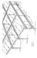
- a glasshouse 1 comprises a support frame 2 which is formed by a number of uprights 3, beams 4 connecting the uprights and trusses 5 running transversely of the beams (fig. 1). Glazed outer walls 6 are formed along the outside of support frame 2, while the upper part of glasshouse 1 is formed by likewise glazed roofs 7 which are supported by beams 4 and trusses 5.
- Each screen installation consists of the actual cover or screen 9, a first edge 10 of which is fixedly connected to support frame 2 of glasshouse 1, and a winding device 11 which co-acts with an opposite, second edge 12 of screen 9.
- Each winding device 11 is formed by a winding tube 13 which is connected to the edge 12 of the screen 9 and a motor 14 which is connected to winding tube 13 via a transmission 15.
- Motor 14 can be a commercially available motor, for instance a three-phase motor, and transmission 15, which is received in a housing 21, can be a self-locking transmission.
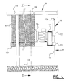
- the screen installations 8 with winding devices 11 are usually arranged in glasshouse 1 at locations where on the one hand space is limited, for instance between the glazed outer wall 6 and a heating installation with pipes 18 (fig. 3), and where the light output must further be maximized. A requirement made of winding device 11 is therefore that it be very compact.
- the motor 14 according to the invention is connected not only drivingly, but also structurally to winding tube 13 and is movable along a guiding 16 relative to this winding tube 13. In the shown embodiment the motor 14 is suspended pivotally from winding tube 13.
- the housing 21 of the transmission herein functions as suspension member.
- Motor guiding 16 is formed by a profiled tube or cylinder 17, along which can move two rotatable guide members 22 which are connected to motor 14.
- Winding tube 13 is itself also movable and during a final phase of its movement can in any case co-act with an end guide 19 of its own.
- This end guide 19 can be at least partly formed by one side of the same tube or cylinder 17 which also defines the first guiding 16.
- winding tube 13 can likewise be provided with one or more rotatable guide members 23 which are arranged in the line of or around winding tube 13.
- motor 14 and drive 15 impede the movement of screen 9 when it reaches an end position, particularly the fully unrolled end position, wherein the winding tube 13 and the edge 12 of screen 9 connected thereto practically touch the ground 25 or for instance a truss 5, in the shown embodiment the motor guiding 16 and the movement of winding tube 13 are in different directions at the location of this end position.
- the tube or cylinder 17 of motor guiding 16 has for this purpose a bent end part 26 which is directed practically transversely of the direction of movement of winding tube 13 and therefore the screen 9.
- the direction of the bent end part 26 is herein chosen such that the movement of motor 14 and transmission 15 along motor guiding 16 is assisted by gravity, whereby this movement can thus also be performed when the drive is not in operation.
- winding device 11 The operation of winding device 11 is now as follows.
- motor 14 When screen 9 must be wholly or partially unwound from its fully wound-up position (at the top in fig. 3), motor 14 is energized such that it begins to rotate in the unwinding direction. This rotation of motor 14 is transferred by transmission 15 to the winding tube 13 which is rotated in the unwinding direction U. Winding tube 13 and the motor and transmission 14, 15 suspended therefrom are herein moved away from the edge 10 of screen 9 which is fixedly connected to a receiving profile 24 of support frame 2. This movement is guided by guide members 22, 23 of the motor and transmission 14, 15 and winding tube 13, which move along the motor guiding 16.
- winding tube 13, motor 14 and transmission 15 on the one hand and the tensioning force in screen 9 on the other one of the two guide members 22 will herein be in engagement with guiding 16.
- the guide roller 23 in the line of winding tube 13 herein follows substantially the same path (designated with positions 23' and 23'') as guide rollers 22 of motor 14 and of transmission 15.
- the motor guiding 16 however deviates from the end guide 19, whereby the path (designated with 23''' and 23IV) of guide member 23 will also deviate from that of guide member 22.
- Motor 14 and transmission 15 are hereby moved away from screen 9, while winding tube 13 can move through unobstructed to the end point formed either by the ground 25, in the case of a vertical screen, or a truss 5 in the case of a horizontal screen.
- the chosen suspension of the motor and transmission 14, 15 from the winding tube 13 thus achieves that the screen can be fully unrolled without the motor and transmission herein impeding the movement, while in any other position of the screen the motor and transmission 14, 15 are suspended thereunder, whereby the shading effect of these components is therefore limited.
- the thus obtained winding device is moreover very compact.
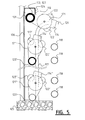
- the motor guiding 116 can be formed by a tube or cylinder 117, the end 120 of which deviates from the path of winding member 113 in the vicinity of the fully wound-up end position of screen 109 (fig. 5). In this variant the motor 114 does in fact hang above winding member 113.
- connection between the motor and the winding member could thus be realized in different manner, while the manner in which the motor and the winding member are guided could also take a different form.
- guide rollers it is possible to envisage guide pins or cams optionally manufactured from a material with low frictional resistance such as Teflon.
- the form of the guide may also be other than shown here. The scope of the invention is therefore defined solely by the claims.
Landscapes
- Engineering & Computer Science (AREA)
- Structural Engineering (AREA)
- Life Sciences & Earth Sciences (AREA)
- Environmental Sciences (AREA)
- Architecture (AREA)
- Civil Engineering (AREA)
- Operating, Guiding And Securing Of Roll- Type Closing Members (AREA)
Abstract
Description
- The invention relates to a device for winding in or winding out a screen, in particular in a glasshouse, comprising at least one winding member connected to a support frame and at least one motor which is connected drivingly to the winding member and which is connected to the support frame. Such a winding device is known, for instance from the
European patent 1 104 230. - In a glasshouse for horticultural products frequent use is made of screens or covers, for instance to save energy by limiting as much as possible the heat loss resulting from radiation or convection, or to screen off incident sunlight, or to prevent the emission of artificial light. Such screens or covers are generally arranged movably along outer walls and roofs of the glasshouse, but can also be used as partition between different departments in the glasshouse. Different systems are known for the opening and closing of such screens and covers. It is thus possible to retract and extend the screens or covers, whereby they come to hang in loops or folds when in the retracted state, while it is also possible to roll up or unroll the covers or screens.
- For rolling up and unrolling of covers or screens, use is generally made of a tubular winding member which is mounted on a free end of the cover or screen, while the opposite end of the cover or screen is fixed to the glasshouse, for instance on the upper part of an outer wall or in the ridge of a roof. When the cover or screen is wound up, the winding tube is rotated, whereby it moves toward the fixed end of the cover or screen. Because the winding tube is fixed to the free end of the cover or screen, the tube can take a relatively long form as the tube is not loaded by its own weight and the weight of the screen, and the danger of bending is thus limited.
- An important requirement laid down for all systems used in a glasshouse, and therefore also for the drive of the winding tube, is that the shading effect thereof be as small as possible. It has therefore already been proposed to drive a winding tube by means of a tube motor received therein. Such a tube motor is formed by an electric motor with a reduction gearing which has a part protruding outside the winding tube which is fixed to a carriage running along a guide in the glasshouse. The tube motor is fixed non-rotatably by this carriage, whereby a rotation of the tube motor is converted into a rotation of the winding tube, which is then moved toward or away from the fixed end of the screen. Such a tube motor is very compact, whereby the shading effect will be relatively small. Owing to its small dimensions the tube motor is moreover suitable for use in the vicinity of outer walls, where the space available will often be very limited as a result of the presence of different structural elements, heating and/or ventilation systems. However, as a result of the small dimensions of the tube motor the power for generating thereby is also limited, while in addition tube motors are not in principle designed for very intensive use and are therefore not very suitable for that purpose.
- Known from the above stated
European patent 1 104 230 is a winding device wherein use is made of a commercially available three-phase motor which is mounted on a pivot arm, which in turn is pivotally mounted in the support frame of the glasshouse. The motor is connected to the winding tube via a worm wheel transmission and a chain transmission connecting thereto. When the motor is energized and the rotation thereof is transmitted to the winding tube via the worm wheel transmission and the chain transmission, the screen is thus wound up or unwound, wherein the pivot arm with the motor suspended therefrom is co-displaced. This known winding device is intended for use in a roof of a so-called foil greenhouse, wherein the screen forms the actual roof. Because the motor is mounted on a pivot arm, this construction takes up a lot of space and is not suitable for use on an outer wall of a glasshouse. - The invention therefore has for its object to provide a winding device of the above described type, which has a considerable power, is suitable for intensive use, has a small shading effect and takes a relatively compact form. According to the invention this is achieved in such a winding device in that the motor is mounted on the winding member and is movable along a guiding relative to the winding member. By mounting the motor on the winding member instead of making use of a tube motor, it is possible to opt for a motor with relatively great power. It is moreover possible, by mounting the motor on the winding member, to dispense with separate suspension mechanisms as in the above discussed prior art while, due to the movability of the motor along the guiding, the motor can take up an optimal position relative to the winding member in all conditions, with a minimal shading effect.
- The winding member is preferably movable relative to the support frame, and the motor guiding and the movement of the winding member are in different directions, at least at the location of an end position of the winding member. Owing to this different direction, the motor can be moved in controlled manner relative to the winding member. At the location of the end position the motor guiding is advantageously directed herein almost transversely of the direction of movement of the winding member, whereby the motor can be moved away from the winding member.
- When the motor is suspended from the winding member and at the location of the end position the motor guiding is directed such that the motor can be moved away under the influence of gravity from the screen connected to the winding member, the screen can be fully closed in simple manner without the motor herein being able to impede the movement of the winding member to its end position.
- In order to avoid undesired displacements of the winding member under the influence of the torque of the motor, an end guide can be provided at the location of the end position of the winding member, along which end guide the winding member is movable.
- In order to limit as much as possible the power required to move the screen, the motor preferably has at least one low-friction guide member co-acting with its guiding. For a stable and uniform movement of the motor, it is recommended to make use of a number of low-friction guide members arranged on both sides of the motor guiding. The winding member advantageously also has at least one low-friction guide member co-acting with the end guide. This guide member can then be arranged in the line of the winding axis of the winding member, whereby a compact construction with an optimum force transfer is obtained. In order to reduce the resistance, the or each guide member can be rotatable.
- An efficient construction is obtained when the motor guiding and the end guide are formed integrally. These guides can for instance be formed by different sides of a single rod or tube.
- When the support frame defines at least one outer wall and/or roof of a glasshouse, the motor guiding runs substantially parallel to the outer wall and/or roof.
- In order to hold the winding speed within reasonable limits and to generate a relatively high torque, transmission means are preferably arranged between the motor and the winding member. In the case that the motor is suspended from the winding member, these transmission means are preferably received in a housing which also functions as suspension member for the motor. Different functions are thus combined in a single structural element, whereby the number of components and the size and shadow effect of the winding device are limited further.
- The invention is now elucidated on the basis of an embodiment, wherein reference is made to the annexed drawing, in which:
- Fig. 1 is a perspective schematic view of a glasshouse with a number of screens and winding devices according to a first embodiment of the invention,
- Fig. 2 is a partly broken-away detail view of a part of the screen and the winding device according to arrow II in fig. 1,
- Fig. 3 is a partly broken-away side view according to arrow III in fig. 2,
- Fig. 4 is a detail view corresponding with fig. 2 of the screen with an alternative embodiment of the winding device, and
- Fig. 5 is a view corresponding with fig. 3 of this second embodiment.
-
- A
glasshouse 1 comprises asupport frame 2 which is formed by a number ofuprights 3, beams 4 connecting the uprights andtrusses 5 running transversely of the beams (fig. 1). Glazedouter walls 6 are formed along the outside ofsupport frame 2, while the upper part ofglasshouse 1 is formed by likewise glazed roofs 7 which are supported by beams 4 andtrusses 5. - At different locations in
glasshouse 1, for instance alongouter walls 6 and roofs 7, there are arrangedscreen installations 8, only one of which is shown here. Each screen installation consists of the actual cover orscreen 9, afirst edge 10 of which is fixedly connected to supportframe 2 ofglasshouse 1, and awinding device 11 which co-acts with an opposite,second edge 12 ofscreen 9. - Each
winding device 11 is formed by awinding tube 13 which is connected to theedge 12 of thescreen 9 and amotor 14 which is connected towinding tube 13 via atransmission 15. Motor 14 can be a commercially available motor, for instance a three-phase motor, andtransmission 15, which is received in ahousing 21, can be a self-locking transmission. - The
screen installations 8 withwinding devices 11 are usually arranged inglasshouse 1 at locations where on the one hand space is limited, for instance between the glazedouter wall 6 and a heating installation with pipes 18 (fig. 3), and where the light output must further be maximized. A requirement made ofwinding device 11 is therefore that it be very compact. In order to achieve this, themotor 14 according to the invention is connected not only drivingly, but also structurally to windingtube 13 and is movable along a guiding 16 relative to thiswinding tube 13. In the shown embodiment themotor 14 is suspended pivotally from windingtube 13. Thehousing 21 of the transmission herein functions as suspension member. - Motor guiding 16 is formed by a profiled tube or
cylinder 17, along which can move tworotatable guide members 22 which are connected tomotor 14.Winding tube 13 is itself also movable and during a final phase of its movement can in any case co-act with anend guide 19 of its own. Thisend guide 19 can be at least partly formed by one side of the same tube orcylinder 17 which also defines the first guiding 16. With a view to the movement along the end guide,winding tube 13 can likewise be provided with one or morerotatable guide members 23 which are arranged in the line of or around windingtube 13. - In order to now prevent that
motor 14 anddrive 15 impede the movement ofscreen 9 when it reaches an end position, particularly the fully unrolled end position, wherein thewinding tube 13 and theedge 12 ofscreen 9 connected thereto practically touch theground 25 or for instance atruss 5, in the shown embodiment the motor guiding 16 and the movement ofwinding tube 13 are in different directions at the location of this end position. The tube orcylinder 17 of motor guiding 16 has for this purpose abent end part 26 which is directed practically transversely of the direction of movement ofwinding tube 13 and therefore thescreen 9. The direction of thebent end part 26 is herein chosen such that the movement ofmotor 14 andtransmission 15 along motor guiding 16 is assisted by gravity, whereby this movement can thus also be performed when the drive is not in operation. - The operation of winding
device 11 is now as follows. Whenscreen 9 must be wholly or partially unwound from its fully wound-up position (at the top in fig. 3),motor 14 is energized such that it begins to rotate in the unwinding direction. This rotation ofmotor 14 is transferred bytransmission 15 to the windingtube 13 which is rotated in the unwinding directionU. Winding tube 13 and the motor andtransmission edge 10 ofscreen 9 which is fixedly connected to a receivingprofile 24 ofsupport frame 2. This movement is guided byguide members transmission tube 13, which move along the motor guiding 16. Depending on the equilibrium between the action of gravity on the assembly ofscreen 9, windingtube 13,motor 14 andtransmission 15 on the one hand and the tensioning force inscreen 9 on the other, one of the twoguide members 22 will herein be in engagement with guiding 16. Theguide roller 23 in the line of windingtube 13 herein follows substantially the same path (designated with positions 23' and 23'') asguide rollers 22 ofmotor 14 and oftransmission 15. In the vicinity of the end of this path, the motor guiding 16 however deviates from theend guide 19, whereby the path (designated with 23''' and 23IV) ofguide member 23 will also deviate from that ofguide member 22.Motor 14 andtransmission 15 are hereby moved away fromscreen 9, while windingtube 13 can move through unobstructed to the end point formed either by theground 25, in the case of a vertical screen, or atruss 5 in the case of a horizontal screen. - The chosen suspension of the motor and
transmission tube 13 thus achieves that the screen can be fully unrolled without the motor and transmission herein impeding the movement, while in any other position of the screen the motor andtransmission - In a variant of winding
device 11, the motor guiding 116 can be formed by a tube orcylinder 117, the end 120 of which deviates from the path of windingmember 113 in the vicinity of the fully wound-up end position of screen 109 (fig. 5). In this variant themotor 114 does in fact hang above windingmember 113. - Although the invention is described above on the basis of an embodiment, it will be apparent that this can be varied in many ways within the scope of the appended claims. The connection between the motor and the winding member could thus be realized in different manner, while the manner in which the motor and the winding member are guided could also take a different form. Instead of guide rollers, it is possible to envisage guide pins or cams optionally manufactured from a material with low frictional resistance such as Teflon. The form of the guide may also be other than shown here. The scope of the invention is therefore defined solely by the claims.
Claims (14)
- Device for winding in or winding out a screen, in particular in a glasshouse, comprising at least one winding member connected to a support frame and at least one motor which is connected drivingly to the winding member and which is connected movably to the support frame, characterized in that the motor is mounted on the winding member and is movable along a guiding relative to the winding member.
- Device as claimed in claim 1, characterized in that the winding member is movable relative to the support frame, and the motor guiding and the movement of the winding member are in different directions, at least at the location of an end position of the winding member.
- Device as claimed in claim 2, characterized in that at the location of the end position the motor guiding is directed almost transversely of the direction of movement of the winding member.
- Device as claimed in claim 2 or 3, characterized in that the motor is suspended from the winding member and at the location of the end position the motor guiding is directed such that the motor can be moved away under the influence of gravity from the screen connected to the winding member.
- Device as claimed in claim 4, characterized by an end guide at the location of the end position along which the winding member is movable.
- Device as claimed in any of the foregoing claims, characterized in that the motor has at least one low-friction guide member co-acting with its guiding.
- Device as claimed in claim 6, characterized by a number of low-friction guide members arranged on both sides of the motor guiding.
- Device as claimed in any of the claims 5-7, characterized in that the winding member has at least one low-friction guide member co-acting with the end guide.
- Device as claimed in claim 8, characterized in that the guide member is arranged in the line of the winding axis of the winding member.
- Device as claimed in any of the claims 6-9, characterized in that the or each guide member is rotatable.
- Device as claimed in any of the claims 5-10, characterized in that the motor guiding and the end guide are formed integrally.
- Device as claimed in any of the claims 5-11, characterized in that the support frame defines at least one outer wall and/or roof of a glasshouse and the motor guiding runs substantially parallel to the outer wall and/or roof.
- Device as claimed in any of the foregoing claims, characterized by transmission means arranged between the motor and the winding member.
- Device as claimed in claims 4 and 13, characterized in that the transmission means are received in a housing which also functions as suspension member for the motor.
Applications Claiming Priority (2)
| Application Number | Priority Date | Filing Date | Title |
|---|---|---|---|
| NL1019930A NL1019930C2 (en) | 2002-02-08 | 2002-02-08 | Device for winding cloth. |
| NL1019930 | 2002-02-08 |
Publications (2)
| Publication Number | Publication Date |
|---|---|
| EP1334655A1 true EP1334655A1 (en) | 2003-08-13 |
| EP1334655B1 EP1334655B1 (en) | 2007-12-05 |
Family
ID=27607208
Family Applications (1)
| Application Number | Title | Priority Date | Filing Date |
|---|---|---|---|
| EP03075346A Expired - Lifetime EP1334655B1 (en) | 2002-02-08 | 2003-02-04 | Device for winding a screen |
Country Status (4)
| Country | Link |
|---|---|
| EP (1) | EP1334655B1 (en) |
| AT (1) | ATE379964T1 (en) |
| DE (1) | DE60317839D1 (en) |
| NL (1) | NL1019930C2 (en) |
Cited By (3)
| Publication number | Priority date | Publication date | Assignee | Title |
|---|---|---|---|---|
| NL1029654C2 (en) | 2005-08-01 | 2007-02-02 | Ridder Drive Systems B V | Greenhouse screen winding device, has counterweight connected to motor via cord for winding around axle extending coaxial to winding and drive shafts |
| ES2308884A1 (en) * | 2006-03-17 | 2008-12-01 | Carlos Moreno Orduña | System for the adaptation of the ceilings/plastic walls of greenhouses to the environmental conditions. (Machine-translation by Google Translate, not legally binding) |
| CN102057846A (en) * | 2010-10-14 | 2011-05-18 | 中农先飞(北京)农业工程技术有限公司 | Device and method for rapidly winding and unwinding outer sunshade screen of sunlight greenhouse |
Citations (5)
| Publication number | Priority date | Publication date | Assignee | Title |
|---|---|---|---|---|
| DE1291929B (en) * | 1965-06-22 | 1969-04-03 | Gartenbautechnik Gmbh & Co Kg | Device for rolling up and unrolling a shading strip connected to a roller bar on a glazed surface |
| DE1509397A1 (en) * | 1965-09-11 | 1969-04-30 | Wilhelm Gabler Gewaechshausbau | Shading device for transparent roofs |
| EP0427677A1 (en) * | 1989-11-08 | 1991-05-15 | Bieri Blachen Ag | Roller-tarpaulin |
| WO2000060192A1 (en) * | 1999-03-31 | 2000-10-12 | Rovero Systems B.V. | Drive for plastic cover foil |
| EP1104230A1 (en) | 1998-08-11 | 2001-06-06 | Henricus Wilhelmus Van Kouwen | Apparatus and method for winding and unwinding cloth for a greenhouse, wherein the torque is limited |
-
2002
- 2002-02-08 NL NL1019930A patent/NL1019930C2/en not_active IP Right Cessation
-
2003
- 2003-02-04 EP EP03075346A patent/EP1334655B1/en not_active Expired - Lifetime
- 2003-02-04 DE DE60317839T patent/DE60317839D1/en not_active Expired - Lifetime
- 2003-02-04 AT AT03075346T patent/ATE379964T1/en not_active IP Right Cessation
Patent Citations (5)
| Publication number | Priority date | Publication date | Assignee | Title |
|---|---|---|---|---|
| DE1291929B (en) * | 1965-06-22 | 1969-04-03 | Gartenbautechnik Gmbh & Co Kg | Device for rolling up and unrolling a shading strip connected to a roller bar on a glazed surface |
| DE1509397A1 (en) * | 1965-09-11 | 1969-04-30 | Wilhelm Gabler Gewaechshausbau | Shading device for transparent roofs |
| EP0427677A1 (en) * | 1989-11-08 | 1991-05-15 | Bieri Blachen Ag | Roller-tarpaulin |
| EP1104230A1 (en) | 1998-08-11 | 2001-06-06 | Henricus Wilhelmus Van Kouwen | Apparatus and method for winding and unwinding cloth for a greenhouse, wherein the torque is limited |
| WO2000060192A1 (en) * | 1999-03-31 | 2000-10-12 | Rovero Systems B.V. | Drive for plastic cover foil |
Cited By (4)
| Publication number | Priority date | Publication date | Assignee | Title |
|---|---|---|---|---|
| NL1029654C2 (en) | 2005-08-01 | 2007-02-02 | Ridder Drive Systems B V | Greenhouse screen winding device, has counterweight connected to motor via cord for winding around axle extending coaxial to winding and drive shafts |
| ES2308884A1 (en) * | 2006-03-17 | 2008-12-01 | Carlos Moreno Orduña | System for the adaptation of the ceilings/plastic walls of greenhouses to the environmental conditions. (Machine-translation by Google Translate, not legally binding) |
| CN102057846A (en) * | 2010-10-14 | 2011-05-18 | 中农先飞(北京)农业工程技术有限公司 | Device and method for rapidly winding and unwinding outer sunshade screen of sunlight greenhouse |
| CN102057846B (en) * | 2010-10-14 | 2013-02-13 | 中农先飞(北京)农业工程技术有限公司 | Device and method for rapidly winding and unwinding outer sunshade screen of sunlight greenhouse |
Also Published As
| Publication number | Publication date |
|---|---|
| ATE379964T1 (en) | 2007-12-15 |
| NL1019930C2 (en) | 2003-08-11 |
| DE60317839D1 (en) | 2008-01-17 |
| EP1334655B1 (en) | 2007-12-05 |
Similar Documents
| Publication | Publication Date | Title |
|---|---|---|
| US6199617B1 (en) | Bi-fold door lift apparatus | |
| US5564234A (en) | Building structure consisting of a framework of uprights and beams covered with a foil | |
| US6457508B1 (en) | Sunshade roll screen | |
| FI76183B (en) | RULLPORT. | |
| US20130087296A1 (en) | Automatic releasable top down shade system and method | |
| KR101762976B1 (en) | Winding device for covering wall openings or windows | |
| US3744544A (en) | Outside venetian blind construction | |
| US20160130873A1 (en) | Winding device for covering of building openings | |
| EP1334655B1 (en) | Device for winding a screen | |
| US10597925B1 (en) | Mechanical mono-fold door | |
| US20030226644A1 (en) | Operating unit for a window covering | |
| DK2730738T3 (en) | Roll-up device to cover the openings in the wall section | |
| US11002058B1 (en) | Mechanical mono-fold door | |
| JP2011256676A (en) | Solar cell panel fitting device of electric solar shading device | |
| US20200325724A1 (en) | Roller blind assembly | |
| EP3594440B1 (en) | Screen system and building | |
| CN219762059U (en) | Quilt winding mechanism and greenhouse | |
| JP4291047B2 (en) | Movable tent | |
| JP4761820B2 (en) | Opening and closing body device | |
| CN218376262U (en) | Sun-shading translational roller shutter driven by solar energy | |
| CN213038708U (en) | Canopy | |
| CN221053028U (en) | Arc membrane structure that opens and shuts | |
| CN116491345A (en) | Quilt winding mechanism and greenhouse | |
| JP4703248B2 (en) | Opening and closing body device | |
| JPS63908Y2 (en) |
Legal Events
| Date | Code | Title | Description |
|---|---|---|---|
| PUAI | Public reference made under article 153(3) epc to a published international application that has entered the european phase |
Free format text: ORIGINAL CODE: 0009012 |
|
| AK | Designated contracting states |
Designated state(s): AT BE BG CH CY CZ DE DK EE ES FI FR GB GR HU IE IT LI LU MC NL PT SE SI SK TR |
|
| AX | Request for extension of the european patent |
Extension state: AL LT LV MK RO |
|
| 17P | Request for examination filed |
Effective date: 20040202 |
|
| AKX | Designation fees paid |
Designated state(s): AT BE BG CH CY CZ DE DK EE ES FI FR GB GR HU IE IT LI LU MC NL PT SE SI SK TR |
|
| 17Q | First examination report despatched |
Effective date: 20061030 |
|
| GRAP | Despatch of communication of intention to grant a patent |
Free format text: ORIGINAL CODE: EPIDOSNIGR1 |
|
| GRAS | Grant fee paid |
Free format text: ORIGINAL CODE: EPIDOSNIGR3 |
|
| GRAA | (expected) grant |
Free format text: ORIGINAL CODE: 0009210 |
|
| AK | Designated contracting states |
Kind code of ref document: B1 Designated state(s): AT BE BG CH CY CZ DE DK EE ES FI FR GB GR HU IE IT LI LU MC NL PT SE SI SK TR |
|
| REG | Reference to a national code |
Ref country code: GB Ref legal event code: FG4D |
|
| REG | Reference to a national code |
Ref country code: IE Ref legal event code: FG4D |
|
| REG | Reference to a national code |
Ref country code: CH Ref legal event code: EP |
|
| REF | Corresponds to: |
Ref document number: 60317839 Country of ref document: DE Date of ref document: 20080117 Kind code of ref document: P |
|
| PG25 | Lapsed in a contracting state [announced via postgrant information from national office to epo] |
Ref country code: LI Free format text: LAPSE BECAUSE OF FAILURE TO SUBMIT A TRANSLATION OF THE DESCRIPTION OR TO PAY THE FEE WITHIN THE PRESCRIBED TIME-LIMIT Effective date: 20071205 Ref country code: CH Free format text: LAPSE BECAUSE OF FAILURE TO SUBMIT A TRANSLATION OF THE DESCRIPTION OR TO PAY THE FEE WITHIN THE PRESCRIBED TIME-LIMIT Effective date: 20071205 Ref country code: NL Free format text: LAPSE BECAUSE OF FAILURE TO SUBMIT A TRANSLATION OF THE DESCRIPTION OR TO PAY THE FEE WITHIN THE PRESCRIBED TIME-LIMIT Effective date: 20071205 Ref country code: SE Free format text: LAPSE BECAUSE OF FAILURE TO SUBMIT A TRANSLATION OF THE DESCRIPTION OR TO PAY THE FEE WITHIN THE PRESCRIBED TIME-LIMIT Effective date: 20080305 Ref country code: ES Free format text: LAPSE BECAUSE OF FAILURE TO SUBMIT A TRANSLATION OF THE DESCRIPTION OR TO PAY THE FEE WITHIN THE PRESCRIBED TIME-LIMIT Effective date: 20080316 |
|
| PG25 | Lapsed in a contracting state [announced via postgrant information from national office to epo] |
Ref country code: FI Free format text: LAPSE BECAUSE OF FAILURE TO SUBMIT A TRANSLATION OF THE DESCRIPTION OR TO PAY THE FEE WITHIN THE PRESCRIBED TIME-LIMIT Effective date: 20071205 Ref country code: SI Free format text: LAPSE BECAUSE OF FAILURE TO SUBMIT A TRANSLATION OF THE DESCRIPTION OR TO PAY THE FEE WITHIN THE PRESCRIBED TIME-LIMIT Effective date: 20071205 |
|
| NLV1 | Nl: lapsed or annulled due to failure to fulfill the requirements of art. 29p and 29m of the patents act | ||
| REG | Reference to a national code |
Ref country code: CH Ref legal event code: PL |
|
| PG25 | Lapsed in a contracting state [announced via postgrant information from national office to epo] |
Ref country code: AT Free format text: LAPSE BECAUSE OF FAILURE TO SUBMIT A TRANSLATION OF THE DESCRIPTION OR TO PAY THE FEE WITHIN THE PRESCRIBED TIME-LIMIT Effective date: 20071205 |
|
| PG25 | Lapsed in a contracting state [announced via postgrant information from national office to epo] |
Ref country code: CZ Free format text: LAPSE BECAUSE OF FAILURE TO SUBMIT A TRANSLATION OF THE DESCRIPTION OR TO PAY THE FEE WITHIN THE PRESCRIBED TIME-LIMIT Effective date: 20071205 |
|
| PG25 | Lapsed in a contracting state [announced via postgrant information from national office to epo] |
Ref country code: BE Free format text: LAPSE BECAUSE OF FAILURE TO SUBMIT A TRANSLATION OF THE DESCRIPTION OR TO PAY THE FEE WITHIN THE PRESCRIBED TIME-LIMIT Effective date: 20071205 Ref country code: SK Free format text: LAPSE BECAUSE OF FAILURE TO SUBMIT A TRANSLATION OF THE DESCRIPTION OR TO PAY THE FEE WITHIN THE PRESCRIBED TIME-LIMIT Effective date: 20071205 |
|
| PG25 | Lapsed in a contracting state [announced via postgrant information from national office to epo] |
Ref country code: PT Free format text: LAPSE BECAUSE OF FAILURE TO SUBMIT A TRANSLATION OF THE DESCRIPTION OR TO PAY THE FEE WITHIN THE PRESCRIBED TIME-LIMIT Effective date: 20080505 |
|
| EN | Fr: translation not filed | ||
| PLBE | No opposition filed within time limit |
Free format text: ORIGINAL CODE: 0009261 |
|
| STAA | Information on the status of an ep patent application or granted ep patent |
Free format text: STATUS: NO OPPOSITION FILED WITHIN TIME LIMIT |
|
| PG25 | Lapsed in a contracting state [announced via postgrant information from national office to epo] |
Ref country code: DE Free format text: LAPSE BECAUSE OF FAILURE TO SUBMIT A TRANSLATION OF THE DESCRIPTION OR TO PAY THE FEE WITHIN THE PRESCRIBED TIME-LIMIT Effective date: 20080306 Ref country code: DK Free format text: LAPSE BECAUSE OF FAILURE TO SUBMIT A TRANSLATION OF THE DESCRIPTION OR TO PAY THE FEE WITHIN THE PRESCRIBED TIME-LIMIT Effective date: 20071205 Ref country code: MC Free format text: LAPSE BECAUSE OF NON-PAYMENT OF DUE FEES Effective date: 20080228 |
|
| 26N | No opposition filed |
Effective date: 20080908 |
|
| GBPC | Gb: european patent ceased through non-payment of renewal fee |
Effective date: 20080305 |
|
| PG25 | Lapsed in a contracting state [announced via postgrant information from national office to epo] |
Ref country code: EE Free format text: LAPSE BECAUSE OF FAILURE TO SUBMIT A TRANSLATION OF THE DESCRIPTION OR TO PAY THE FEE WITHIN THE PRESCRIBED TIME-LIMIT Effective date: 20071205 Ref country code: GR Free format text: LAPSE BECAUSE OF FAILURE TO SUBMIT A TRANSLATION OF THE DESCRIPTION OR TO PAY THE FEE WITHIN THE PRESCRIBED TIME-LIMIT Effective date: 20080306 Ref country code: IE Free format text: LAPSE BECAUSE OF NON-PAYMENT OF DUE FEES Effective date: 20080204 |
|
| PG25 | Lapsed in a contracting state [announced via postgrant information from national office to epo] |
Ref country code: BG Free format text: LAPSE BECAUSE OF FAILURE TO SUBMIT A TRANSLATION OF THE DESCRIPTION OR TO PAY THE FEE WITHIN THE PRESCRIBED TIME-LIMIT Effective date: 20080305 Ref country code: FR Free format text: LAPSE BECAUSE OF FAILURE TO SUBMIT A TRANSLATION OF THE DESCRIPTION OR TO PAY THE FEE WITHIN THE PRESCRIBED TIME-LIMIT Effective date: 20081003 |
|
| PG25 | Lapsed in a contracting state [announced via postgrant information from national office to epo] |
Ref country code: GB Free format text: LAPSE BECAUSE OF NON-PAYMENT OF DUE FEES Effective date: 20080305 |
|
| PG25 | Lapsed in a contracting state [announced via postgrant information from national office to epo] |
Ref country code: CY Free format text: LAPSE BECAUSE OF FAILURE TO SUBMIT A TRANSLATION OF THE DESCRIPTION OR TO PAY THE FEE WITHIN THE PRESCRIBED TIME-LIMIT Effective date: 20071205 |
|
| PG25 | Lapsed in a contracting state [announced via postgrant information from national office to epo] |
Ref country code: HU Free format text: LAPSE BECAUSE OF FAILURE TO SUBMIT A TRANSLATION OF THE DESCRIPTION OR TO PAY THE FEE WITHIN THE PRESCRIBED TIME-LIMIT Effective date: 20080606 Ref country code: LU Free format text: LAPSE BECAUSE OF NON-PAYMENT OF DUE FEES Effective date: 20080204 |
|
| PG25 | Lapsed in a contracting state [announced via postgrant information from national office to epo] |
Ref country code: TR Free format text: LAPSE BECAUSE OF FAILURE TO SUBMIT A TRANSLATION OF THE DESCRIPTION OR TO PAY THE FEE WITHIN THE PRESCRIBED TIME-LIMIT Effective date: 20071205 |
|
| PG25 | Lapsed in a contracting state [announced via postgrant information from national office to epo] |
Ref country code: IT Free format text: LAPSE BECAUSE OF NON-PAYMENT OF DUE FEES Effective date: 20080229 |