EP1333358A2 - Computergehäuse - Google Patents
Computergehäuse Download PDFInfo
- Publication number
- EP1333358A2 EP1333358A2 EP02027401A EP02027401A EP1333358A2 EP 1333358 A2 EP1333358 A2 EP 1333358A2 EP 02027401 A EP02027401 A EP 02027401A EP 02027401 A EP02027401 A EP 02027401A EP 1333358 A2 EP1333358 A2 EP 1333358A2
- Authority
- EP
- European Patent Office
- Prior art keywords
- slot
- computer housing
- openings
- contact spring
- webs
- Prior art date
- Legal status (The legal status is an assumption and is not a legal conclusion. Google has not performed a legal analysis and makes no representation as to the accuracy of the status listed.)
- Withdrawn
Links
Images


Classifications
-
- G—PHYSICS
- G06—COMPUTING OR CALCULATING; COUNTING
- G06F—ELECTRIC DIGITAL DATA PROCESSING
- G06F1/00—Details not covered by groups G06F3/00 - G06F13/00 and G06F21/00
- G06F1/16—Constructional details or arrangements
- G06F1/18—Packaging or power distribution
- G06F1/183—Internal mounting support structures, e.g. for supporting printed circuit boards
- G06F1/185—Mounting of expansion boards
-
- G—PHYSICS
- G06—COMPUTING OR CALCULATING; COUNTING
- G06F—ELECTRIC DIGITAL DATA PROCESSING
- G06F1/00—Details not covered by groups G06F3/00 - G06F13/00 and G06F21/00
- G06F1/16—Constructional details or arrangements
- G06F1/18—Packaging or power distribution
- G06F1/183—Internal mounting support structures, e.g. for supporting printed circuit boards
- G06F1/184—Mounting of motherboards
-
- G—PHYSICS
- G06—COMPUTING OR CALCULATING; COUNTING
- G06F—ELECTRIC DIGITAL DATA PROCESSING
- G06F1/00—Details not covered by groups G06F3/00 - G06F13/00 and G06F21/00
- G06F1/16—Constructional details or arrangements
- G06F1/18—Packaging or power distribution
- G06F1/183—Internal mounting support structures, e.g. for supporting printed circuit boards
- G06F1/185—Mounting of expansion boards
- G06F1/186—Securing of expansion boards in correspondence to slots provided at the computer enclosure
-
- G—PHYSICS
- G06—COMPUTING OR CALCULATING; COUNTING
- G06F—ELECTRIC DIGITAL DATA PROCESSING
- G06F1/00—Details not covered by groups G06F3/00 - G06F13/00 and G06F21/00
- G06F1/16—Constructional details or arrangements
- G06F1/20—Cooling means
Definitions
- the invention relates to a computer housing with a bottom wall and at least two side walls, one on Sidewall a slot angle is missing with a short horizontal Section and a longer vertical section is in which slot openings arranged side by side are formed, which are spaced apart by webs are.
- Plug-in cards can be inserted into the computer housing from above, as a rule PCI cards to be inserted. Per slot opening in the slot angle field a PCI card can be added, provided that A corresponding motherboard for contacting the PCI plug-in card PCI slot is provided.
- the invention is therefore based on the object of the generic type To develop computer case so that at close PCI cards arranged next to each other ensure optimal air throughput as well as optimal EMC contacting in the area the slot angle field is guaranteed.
- the object is achieved in that the Contact springs for contacting between the slot openings the slot angle as well as ventilation openings are provided are.
- the contact spring formed on both sides of a web and are the ventilation openings arranged within the contact springs.
- a relief in assembly and manufacture can be achieved in that the contact spring for both sides is formed in one piece and the two sides via tabs are connected, via which the contact springs with the webs can be riveted.
- contact spring is bevelled on both sides at least on the top, so that for inserting the slot angle on the plug-in cards Insertion funnel is created.
- the PCI cards also face the slot angle field usually an adapter with which they can be used in appropriate Guides inserted on the opposite side walls can be.
- the PCI cards can also be achieved opposite the ventilation openings on the webs between the slot angle openings on the ventilation openings on the other side of the computer case, so that a horizontal air flow through the computer case or PCI chassis.
- Figure 1 shows a computer housing or a PCI chassis in an oblique view.
- the computer case has one Bottom wall 1, two side walls 2 and a slot angle field 3 on one of the two side walls 2.
- the slot angle field 3 consists of a horizontal short Section 4, which is aligned parallel to the bottom wall 1 and a longer vertical section 5, which is vertical to the bottom wall 1 and parallel to the side wall 2 is aligned and on one side the side wall 2 forms in this area.
- the slot openings 6 are spaced apart from one another by webs 7.
- the computer case shown are three plug-in cards 8 plugged in.
- the plug-in cards 8 are in corresponding slots 9 in a motherboard mounted parallel to the bottom wall 1 plugged in.
- the cards 8 each have the front Usual standard aperture or the usual standard slot angle 11 on which with its short horizontal section the horizontal section 4 of the slot angle field rests and with its vertical section the slot openings 6 closes and rests laterally on the webs 7. At the short horizontal section 4 of the slot angle field Clamping parts 12 are provided for fixing the slot bracket 11.
- contact springs 13 are provided on the webs according to the invention arranged. To ensure good ventilation at the same time to achieve closely spaced PCI cards 8 are within the contact springs 13 and also above and below in the Web ventilation openings 14 are provided.
- the contact spring 13 is based on Figures 2, 3 and 4 and the ventilation openings 14 explained with reference to Figure 2.
- Figure 2 shows a side view of a side wall 2 of the Computer housing with a view of the inside of the slot angle field 3.
- the slot openings 6 are as already described for figure 1 spaced apart by the webs 7, wherein in the Web 7 and also slightly below the webs 7, the ventilation openings 14 are provided.
- the contact spring 13 is like this formed that the ventilation openings 14 on both sides of the Contact spring 13 are surrounded, but not covered by this become.
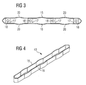
- Figures 3 and 4 show the contact spring 13. It is off two symmetrical halves 15 and 16 built over four Tabs 17 are interconnected. In the tabs 17 are Corresponding holes 18 are provided through which the contact spring with corresponding holes 19 in the webs 7 of Slot angle field 3 can be riveted.
- the two halves 15 and 16 each have a slightly outward curvature 20. This can spring back inward and serves as Contact point to the sides of the slot bracket 11.
- the two halves are chamfered inwards, so that as shown in Figure 2 for the insertion of the Slot angle or the card covers on the PCI cards 8 an insertion funnel is created.
- the two halves 15, 16 of the contact spring 13 have a height of a few millimeters, so that also very twisted or slightly inclined slot angles can be safely contacted.
- the contact spring 13 thus becomes a safe one EMC contact achieved and through the arrangement of the ventilation openings 14 within the contact spring 13 as well Above and below it is ensured that even the closely spaced Cards are cooled sufficiently.
- Airflow through the PCI chassis between the PCI cards are also possible on the other side wall 2 ventilation openings 21 are formed, which also essentially arranged in the space between the PCI cards are.
- the PCI cards 8 can also be used without problems the risk of short circuits during operation (hotplug) it will be exchanged.
Landscapes
- Engineering & Computer Science (AREA)
- Theoretical Computer Science (AREA)
- General Engineering & Computer Science (AREA)
- Computer Hardware Design (AREA)
- Human Computer Interaction (AREA)
- Physics & Mathematics (AREA)
- General Physics & Mathematics (AREA)
- Power Engineering (AREA)
- Cooling Or The Like Of Electrical Apparatus (AREA)
- Mounting Of Printed Circuit Boards And The Like (AREA)
Abstract
Description
- Figur 1
- eine Schrägansicht des Computergehäuses,
- Figur 2
- ein Teil des Slotwinkelfeldes in der Ansicht vom Inneren des Computergehäuses,
- Figur 3
- eine Seitenansicht der Kontaktfeder und
- Figur 4
- die Kontaktfeder in Schrägansicht.
- 1
- Bodenwandung
- 2
- Seitenwandungen
- 3
- Slotwinkelfeld
- 4
- horizontaler Abschnitt
- 5
- vertikaler Abschnitt
- 6
- Slotöffnungen
- 7
- Stege
- 8
- Steckkarten
- 9
- Slots
- 10
- Motherboard
- 11
- Slotwinkel
- 12
- Klemmteile
- 13
- Kontaktfedern
- 14
- Lüftungsöffnungen
- 15
- Hälfte
- 16
- Hälfte
- 17
- Laschen
- 18
- Bohrung
- 19
- Bohrung
- 20
- Wölbung
- 21
- Luftöffnung
- 22
- Führungen
Claims (7)
- Computergehäuse mit einer Bodenwandung (1) und zumindest zwei Seitenwandungen (2), wobei an einer Seitenwandung (2) ein Slotwinkelfeld (3) mit einem kurzen horizontalen Abschnitt (4) und einem längeren vertikalen Abschnitt (5) vorgesehen ist, in welchem nebeneinander angeordnete Slotöffnungen (6) ausgebildet sind, die durch Stege (7) untereinander beabstandet sind,
dadurch gekennzeichnet, daß
an den Stegen (7) zwischen den Slotöffnungen (6) Kontaktfedern (13) zur Kontaktierung der Slotwinkel (11) sowie auch Lüftungsöffnungen (14) vorgesehen sind. - Computergehäuse nach Anspruch 1,
dadurch gekennzeichnet, daß
die Kontaktfedern (13) über die volle Höhe der senkrechten Abschnitte (5) ausgebildet sind. - Computergehäuse nach Anspruch 1 oder 2,
dadurch gekennzeichnet, daß
eine Kontaktfeder (13) jeweils beidseitig des Steges (7) ausgebildet ist und innerhalb der beiden Seiten der Kontaktfeder (13) die Luftöffnungen (14) angeordnet sind. - Computergehäuse nach Anspruch 3,
dadurch gekennzeichnet, daß
die beiden Seiten der Kontaktfeder (13) durch Laschen (17) verbunden sind, über welche die Kontaktfeder (13) an den Stegen (7) befestigbar ist. - Computergehäuse nach einem der Ansprüche 1 bis 4,
dadurch gekennzeichnet, daß
die Kontaktfeder (13) zumindest an der Oberseite beidseitig abgeschrägt ist, so daß für das Einstecken der Slotwinkel (11) ein Einführtrichter entsteht. - Computergehäuse nach einem der Ansprüche 1 bis 5,
dadurch gekennzeichnet, daß
an der Seitenwandung (2) gegenüber des Slotfeldes (3) ebenso Lüftungsöffnungen (21) vorgesehen sind. - Computergehäuse nach Anspruch 6,
dadurch gekennzeichnet, daß
die Lüftungsöffnungen (21) fluchtend gegenüberliegend den Lüftungsöffnungen (14) an der Seite des Slotfeldes (3) angeordnet sind.
Applications Claiming Priority (2)
| Application Number | Priority Date | Filing Date | Title |
|---|---|---|---|
| DE2002100054 DE10200054C2 (de) | 2002-01-02 | 2002-01-02 | Computergehäuse |
| DE10200054 | 2002-01-02 |
Publications (2)
| Publication Number | Publication Date |
|---|---|
| EP1333358A2 true EP1333358A2 (de) | 2003-08-06 |
| EP1333358A3 EP1333358A3 (de) | 2005-12-07 |
Family
ID=7711457
Family Applications (1)
| Application Number | Title | Priority Date | Filing Date |
|---|---|---|---|
| EP02027401A Withdrawn EP1333358A3 (de) | 2002-01-02 | 2002-12-09 | Computergehäuse |
Country Status (2)
| Country | Link |
|---|---|
| EP (1) | EP1333358A3 (de) |
| DE (1) | DE10200054C2 (de) |
Cited By (1)
| Publication number | Priority date | Publication date | Assignee | Title |
|---|---|---|---|---|
| WO2013140461A3 (en) * | 2012-03-23 | 2013-11-14 | Hitachi, Ltd. | Storage system |
Family Cites Families (9)
| Publication number | Priority date | Publication date | Assignee | Title |
|---|---|---|---|---|
| US4019099A (en) * | 1976-01-15 | 1977-04-19 | Calabro Anthony Denis | Circuit board mounting device |
| DE3539404A1 (de) * | 1985-11-07 | 1987-05-14 | Rohde & Schwarz | Fuehrungsleiste fuer leiterplatten |
| US5774330A (en) * | 1995-05-01 | 1998-06-30 | Apple Computer, Inc. | Apparatus for supporting operational components of a personal computer |
| DE29510599U1 (de) * | 1995-06-29 | 1995-11-16 | Siemens Nixdorf Informationssysteme AG, 33106 Paderborn | Abdeckvorrichtung für durch Öffnungen in einer Gehäusewandung eines Datenverarbeitungsgerätes zugängliche Einbauplätze für dort einsetzbare Standard-Flachbaugruppen |
| DE19609887C1 (de) * | 1996-03-13 | 1997-07-24 | Siemens Nixdorf Inf Syst | Gerätechassis für elektronische Geräte |
| US5650922A (en) * | 1996-04-16 | 1997-07-22 | Ho; Hsin Chien | Computer interface card mounting structure |
| US5929376A (en) * | 1997-06-20 | 1999-07-27 | Tektronix, Inc. | Electromagnetic interference shield and method of manufacturing |
| US6403879B1 (en) * | 2000-06-21 | 2002-06-11 | Hewlett-Packard Company | Electronic chassis having an EMI gasket and integral ventilation holes |
| US6480392B1 (en) * | 2001-07-17 | 2002-11-12 | Lite-On Enclosure Inc. | Retaining and fixing structure of interface card |
-
2002
- 2002-01-02 DE DE2002100054 patent/DE10200054C2/de not_active Expired - Fee Related
- 2002-12-09 EP EP02027401A patent/EP1333358A3/de not_active Withdrawn
Cited By (2)
| Publication number | Priority date | Publication date | Assignee | Title |
|---|---|---|---|---|
| WO2013140461A3 (en) * | 2012-03-23 | 2013-11-14 | Hitachi, Ltd. | Storage system |
| US8897006B2 (en) | 2012-03-23 | 2014-11-25 | Hitachi, Ltd. | Cooling technique for a storage system |
Also Published As
| Publication number | Publication date |
|---|---|
| DE10200054C2 (de) | 2003-10-30 |
| DE10200054A1 (de) | 2003-07-17 |
| EP1333358A3 (de) | 2005-12-07 |
Similar Documents
| Publication | Publication Date | Title |
|---|---|---|
| EP0944297B1 (de) | Geräteschrank | |
| EP0752199B1 (de) | Trägerplatte für baugruppen | |
| DE102004038379B4 (de) | Elektrische Verbinderbox, die einen Überprüfungsabschnitt für eine Schlitzbreite, eines Stimmgabelähnlichen Anschlusses aufweist | |
| DE69121270T2 (de) | Zweiteilige Buchseneinheit für modularen Steckeraufbau | |
| DE4310517C2 (de) | Vorrichtung zum Lesen von Chipkarten | |
| WO2010127882A1 (de) | Serverrahmen sowie zum einsatz in dem serverrahmen geeigneter einschubserver | |
| DE102006034199A1 (de) | Aufnahmestruktur für eine Platine | |
| EP0575436A1 (de) | Vorrichtung zur kontaktierung von wanne und haube eines geschlossenen gehäuses. | |
| WO1997034453A1 (de) | Baugruppe eines elektrischen gerätes | |
| EP0199029B1 (de) | Codiervorrichtung für in einen Baugruppenrahmen einschiebbare Baugruppen | |
| DE3608046A1 (de) | Baugruppentraeger fuer elektronische und/oder elektromechanische einschubbaugruppen | |
| WO1991015102A1 (de) | Halteeinrichtung für steckkarten | |
| DE10303072A1 (de) | Verbinder und Meßgerät | |
| DE3503813A1 (de) | Baugruppe fuer baugruppentraeger der nachrichtentechnik | |
| DE69905681T2 (de) | Steckverbinder auf Leiterplatte, bestehend aus Gegenstecker und Buchse | |
| DE10200054C2 (de) | Computergehäuse | |
| EP0299199A2 (de) | Baugruppenrahmen zur Aufnahme von einschiebbaren elektrischen Leiterplatten | |
| EP0627130B1 (de) | Steckverbinder | |
| DE3524035C2 (de) | ||
| DE4408542C1 (de) | Trägerplatte für Baugruppen | |
| EP1705976A2 (de) | Messgerätmodul | |
| DE3210936C2 (de) | Steckverbindung | |
| DE2613704C2 (de) | Elektrische Steckvorrichtung | |
| DE3922882A1 (de) | Verriegelbarer steckverbinder | |
| DE29904760U1 (de) | Schubladengarnitur |
Legal Events
| Date | Code | Title | Description |
|---|---|---|---|
| PUAI | Public reference made under article 153(3) epc to a published international application that has entered the european phase |
Free format text: ORIGINAL CODE: 0009012 |
|
| AK | Designated contracting states |
Designated state(s): AT BE BG CH CY CZ DE DK EE ES FI FR GB GR IE IT LI LU MC NL PT SE SI SK TR |
|
| AX | Request for extension of the european patent |
Extension state: AL LT LV MK RO |
|
| RAP1 | Party data changed (applicant data changed or rights of an application transferred) |
Owner name: FUJITSU SIEMENS COMPUTERS GMBH |
|
| PUAL | Search report despatched |
Free format text: ORIGINAL CODE: 0009013 |
|
| AK | Designated contracting states |
Kind code of ref document: A3 Designated state(s): AT BE BG CH CY CZ DE DK EE ES FI FR GB GR IE IT LI LU MC NL PT SE SI SK TR |
|
| AX | Request for extension of the european patent |
Extension state: AL LT LV MK RO |
|
| 17P | Request for examination filed |
Effective date: 20060123 |
|
| AKX | Designation fees paid |
Designated state(s): DE FR GB NL |
|
| STAA | Information on the status of an ep patent application or granted ep patent |
Free format text: STATUS: THE APPLICATION IS DEEMED TO BE WITHDRAWN |
|
| 18D | Application deemed to be withdrawn |
Effective date: 20110701 |