EP1333202A1 - Method and device for controlling the gear shifting of a vehicle transmission - Google Patents
Method and device for controlling the gear shifting of a vehicle transmission Download PDFInfo
- Publication number
- EP1333202A1 EP1333202A1 EP03075145A EP03075145A EP1333202A1 EP 1333202 A1 EP1333202 A1 EP 1333202A1 EP 03075145 A EP03075145 A EP 03075145A EP 03075145 A EP03075145 A EP 03075145A EP 1333202 A1 EP1333202 A1 EP 1333202A1
- Authority
- EP
- European Patent Office
- Prior art keywords
- electric motor
- motor
- synchronization
- speed
- control element
- Prior art date
- Legal status (The legal status is an assumption and is not a legal conclusion. Google has not performed a legal analysis and makes no representation as to the accuracy of the status listed.)
- Withdrawn
Links
Images

Classifications
-
- F—MECHANICAL ENGINEERING; LIGHTING; HEATING; WEAPONS; BLASTING
- F16—ENGINEERING ELEMENTS AND UNITS; GENERAL MEASURES FOR PRODUCING AND MAINTAINING EFFECTIVE FUNCTIONING OF MACHINES OR INSTALLATIONS; THERMAL INSULATION IN GENERAL
- F16H—GEARING
- F16H61/00—Control functions within control units of change-speed- or reversing-gearings for conveying rotary motion ; Control of exclusively fluid gearing, friction gearing, gearings with endless flexible members or other particular types of gearing
- F16H61/26—Generation or transmission of movements for final actuating mechanisms
- F16H61/28—Generation or transmission of movements for final actuating mechanisms with at least one movement of the final actuating mechanism being caused by a non-mechanical force, e.g. power-assisted
- F16H61/32—Electric motors actuators or related electrical control means therefor
-
- F—MECHANICAL ENGINEERING; LIGHTING; HEATING; WEAPONS; BLASTING
- F16—ENGINEERING ELEMENTS AND UNITS; GENERAL MEASURES FOR PRODUCING AND MAINTAINING EFFECTIVE FUNCTIONING OF MACHINES OR INSTALLATIONS; THERMAL INSULATION IN GENERAL
- F16H—GEARING
- F16H61/00—Control functions within control units of change-speed- or reversing-gearings for conveying rotary motion ; Control of exclusively fluid gearing, friction gearing, gearings with endless flexible members or other particular types of gearing
- F16H61/26—Generation or transmission of movements for final actuating mechanisms
- F16H61/28—Generation or transmission of movements for final actuating mechanisms with at least one movement of the final actuating mechanism being caused by a non-mechanical force, e.g. power-assisted
- F16H2061/2823—Controlling actuator force way characteristic, i.e. controlling force or movement depending on the actuator position, e.g. for adapting force to synchronisation and engagement of gear clutch
-
- F—MECHANICAL ENGINEERING; LIGHTING; HEATING; WEAPONS; BLASTING
- F16—ENGINEERING ELEMENTS AND UNITS; GENERAL MEASURES FOR PRODUCING AND MAINTAINING EFFECTIVE FUNCTIONING OF MACHINES OR INSTALLATIONS; THERMAL INSULATION IN GENERAL
- F16H—GEARING
- F16H63/00—Control outputs from the control unit to change-speed- or reversing-gearings for conveying rotary motion or to other devices than the final output mechanism
- F16H63/02—Final output mechanisms therefor; Actuating means for the final output mechanisms
- F16H63/30—Constructional features of the final output mechanisms
- F16H63/304—Constructional features of the final output mechanisms the final output mechanisms comprising elements moved by electrical or magnetic force
Definitions
- a power unit comprising a electric motor and means of transformation of movement, connected to an actuating element by a elastically deformable element.
- the element actuation such as a lever or a fork, first move means of synchronization to make the speeds of rotation of the gears from the transmission ratio to engage and primary and secondary trees of the box, then dog clutch means which ensure the securing in rotation of these pinions and gearbox shafts.
- Sensors position are provided on either side of the element elastically deformable and are connected to means information processing who order power to the unit's electric motor driving.
- the electric motor acts on the elastically deformable element which stores mechanical energy (typically by compression of a spring) until the force that this element exerts on the synchronization means exceeds a resistant effort opposed by these means. Then, synchronization being ensured, relaxation of the elastically deformable element causes the dog clutch and engagement of the transmission report.
- mechanical energy typically by compression of a spring
- the object of the invention is in particular to provide a simple, effective and economical solution to these problems.
- It relates to a method and a device for controls that allow rapid gear change, without high effort on synchronization means no violent impact on the end of travel limit stops interconnection, and which are less expensive and less bulky than the technical means earlier.
- Using a low electric motor inertia allows shorter response times, faster variations in speed and a reduction in the electric consumption of the motor, as well as less heating, allowing more high frequency of gear changes.
- the use of a low inertia electric motor also allows to control more precisely what engine, and therefore to use a rigid or high stiffness between the electric motor and the high effortless control element on the synchronization means or violent shock on dog clutch end stops. Suppression of the deformable elastic element used in the prior art results in a reduction of space and cost and allows use from one position sensor, instead of two.
- this process makes it possible to reduce the duration of the gear change in a box of robotic speeds, while avoiding too much effort high on synchronization means and shock violent on the end of travel limit stops interconnection.
- the invention also provides a device for gearshift control in a box of motor vehicle speeds, especially a robotic gearbox, this device comprising at least one electric motor driving a movable control element in the box speeds for synchronization and interconnection of a transmission ratio, and control means of said electric motor, characterized in that the electric motor is a low inertia motor and is connected to the control element by a connection to high stiffness, a position sensor being associated said control element and connected to the means of electric motor control to control the rotational speed of this motor at the position of the control element.
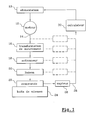
- FIG. 1 a gearshift control device according to the invention, which is used for the engagement of a transmission ratio in a gearbox of motor vehicle, in particular a box of robotic gears, after selecting this gear ratio transmission.
- the engagement of a speed in a motor vehicle gearbox, robotized or not includes a first phase of selection of a corresponding transmission report for example to a transverse movement of a lever gear change in a gear grid, and a second gear shift phase corresponding to a longitudinal displacement of the lever the change of speed in the aforementioned grid and during which the transmission ratio selected is engaged.
- gear rotation speeds of the ratio of selected transmission which usually includes a pinion carried by a primary gearbox shaft speeds, driven in rotation by the motor internal combustion of the motor vehicle, and a pinion carried by the secondary shaft or output of the gearbox, connected by a transmission to the vehicle's drive wheels automobile.
- the travel of the dog clutch means is limited by a limit stop and we try to avoid too violent shocks on this stop, which cause noise and which can cause abnormal wear and degradation of parts in contact.
- the electric motor 12 is connected by its shaft output 14, to means 16 for transforming movement, such as a gearbox gears or the like, connected by means actuators 18 and connecting means 20 to a shift control element 22 in the gearbox 24 of the motor vehicle, this element 22 being or comprising for example a lever movable in pivoting or in translation, such as in particular that a gear shift range of transmission.
- the means 16, 18, 20, 22 connecting the output shaft of the motor 12 to the means of synchronization and interconnection in the box 24 gears constitute a high stiffness connection which has a small elastic deformation stroke, at during a gear change, less than the stroke synchronization means and that of the means interconnection.
- a control signal is sent by means 30 of information processing means 10 power supply to motor 12, which is powered by a direct current of intensity determined, preferably corresponding to a speed maximum rotation of the motor 12.
- the element of command 22 is then driven at maximum speed for moving a walkman or a sleeve in the gearbox, this walkman or sleeve coming successively to act on the means of synchronization, then on the dog clutch means.
- the solid line curve represents the variation of the speed of rotation V1 of the motor 12 as a function of time t
- the cross curve represents the variation of the speed V2 of the walkman or sleeve as a function of time t, in a passage of speed.
- the two curves V1 and V2 are represented with the same maximum values and the same minimum values even if, in reality, one of these speeds is a speed of rotation and the other a speed of translation.
- the speed of rotation of the motor 12 is controlled according to signal 28 from position of the control element 22 supplied by the sensor 26 to means 30 for processing information, and we plan to slow down significantly the speed V1 of the front motor 12 docking of the player or the sleeve on the means synchronization.
- the position of the docking point synchronization means being known, for example calculation and / or by learning as indicated in the Applicant's previous patent applications, we controls at time t1 the slowing down of the motor 12 so as to arrive at time t2 at the docking point on the means of synchronization with a speed about 0.1 m / s for example, which is very clearly lower than the maximum speed of movement of the player or sleeve, to reduce to a value admissible the effort applied to the means of synchronization and thus not to damage them.
- the duration t2-t3 represents the duration of the synchronization.
- the speeds of rotation of the gears from the transmission ratio to engage and primary and secondary trees of the gearboxes are equal and the dog clutch can take place.
- the restart of the motor 12 whose speed V1 increases very quickly to its maximum value or up to the vicinity of this maximum value before to be reduced again to zero at time t5, which corresponds to the end of the dog clutch, determined by an end stop.
Abstract
Description
La présente invention concerne un procédé et un dispositif de commande du passage des vitesses dans une boíte de vitesses de véhicule automobile, en particulier une boíte de vitesses robotisée.The present invention relates to a method and a gear shift control device in a motor vehicle gearbox, in particularly a robotic gearbox.
On a déjà proposé, dans les documents WO 99/56040 et FR 0016429, de commander les passages de vitesse au moyen d'une unité motrice comprenant un moteur électrique et des moyens de transformation de mouvement, reliée à un élément d'actionnement par un élément élastiquement déformable. L'élément d'actionnement, tel par exemple qu'un levier ou une fourchette, déplace d'abord des moyens de synchronisation pour rendre égales les vitesses de rotation des pignons du rapport de transmission à engager et des arbres primaire et secondaire de la boíte, puis des moyens de crabotage qui assurent la solidarisation en rotation de ces pignons et des arbres de la boíte de vitesses. Des capteurs de position sont prévus de part et d'autre de l'élément élastiquement déformable et sont reliés à des moyens de traitement de l'information qui commandent l'alimentation du moteur électrique de l'unité motrice.We have already proposed, in the documents WO 99/56040 and FR 0016429, to order the passages of speed by means of a power unit comprising a electric motor and means of transformation of movement, connected to an actuating element by a elastically deformable element. The element actuation, such as a lever or a fork, first move means of synchronization to make the speeds of rotation of the gears from the transmission ratio to engage and primary and secondary trees of the box, then dog clutch means which ensure the securing in rotation of these pinions and gearbox shafts. Sensors position are provided on either side of the element elastically deformable and are connected to means information processing who order power to the unit's electric motor driving.
Pour un passage de vitesse, le moteur électrique agit sur l'élément élastiquement déformable qui emmagasine une énergie mécanique (typiquement par compression d'un ressort) jusqu'à ce que l'effort que cet élément exerce sur les moyens de synchronisation dépasse un effort résistant opposé par ces moyens. Ensuite, la synchronisation étant assurée, la détente de l'élément élastiquement déformable provoque le crabotage et l'engagement du rapport de transmission. Pour éviter un effort trop violent à l'accostage sur les moyens de synchronisation et pour éviter également un choc brutal sur une butée de fin de course de crabotage, il faut piloter le moteur électrique à partir des informations fournies par les deux capteurs de position, de façon à moduler la compression de l'élément élastiquement déformable.For a gear change, the electric motor acts on the elastically deformable element which stores mechanical energy (typically by compression of a spring) until the force that this element exerts on the synchronization means exceeds a resistant effort opposed by these means. Then, synchronization being ensured, relaxation of the elastically deformable element causes the dog clutch and engagement of the transmission report. To avoid an excessively violent effort when docking on means of synchronization and to avoid also a brutal shock on an end stop of dog clutch race, you have to drive the engine electric from information provided by two position sensors, so as to modulate the compression of the elastically deformable element.
Ce pilotage en effort n'est pas simple à réaliser. Les autres inconvénients de ces moyens connus sont essentiellement leur encombrement et leur coût, en raison de la présence nécessaire de l'élément élastiquement déformable et des deux capteurs de position.This effort control is not easy to achieve. The other disadvantages of these means known are essentially their size and cost, due to the necessary presence of the elastically deformable element and of the two position sensors.
Il serait possible de supprimer l'élément élastiquement déformable entre l'unité motrice et l'élément d'actionnement, mais il faudrait alors ralentir le moteur électrique pour éviter des efforts trop élevés sur les moyens de synchronisation et des chocs trop violents sur les butées de fin de course de crabotage, ce qui allongerait sensiblement la durée du passage de vitesse.It would be possible to delete the element elastically deformable between the drive unit and the actuating element, but then slow the electric motor to avoid efforts too high on the synchronization means and Too violent shocks on the end stops interconnection, which would significantly lengthen the duration of the gear change.
L'invention a notamment pour but d'apporter une solution simple, efficace et économique à ces problèmes.The object of the invention is in particular to provide a simple, effective and economical solution to these problems.
Elle a pour objet un procédé et un dispositif de commande qui permettent un passage de vitesse rapide, sans effort élevé sur les moyens de synchronisation ni choc violent sur les butées de fin de course de crabotage, et qui sont moins coûteux et moins encombrants que les moyens de la technique antérieure.It relates to a method and a device for controls that allow rapid gear change, without high effort on synchronization means no violent impact on the end of travel limit stops interconnection, and which are less expensive and less bulky than the technical means earlier.
Elle propose à cet effet un procédé de commande du passage de vitesse dans une boíte de vitesses de véhicule automobile, en particulier une boíte de vitesses robotisée, dans laquelle la synchronisation et le crabotage d'un rapport de transmission sont réalisés par déplacement d'un élément de commande au moyen d'un moteur électrique, caractérisé en ce que, pour réduire la consommation électrique et l'échauffement et pour accélérer le passage de vitesse, on entraíne ledit élément de commande par un moteur électrique à faible inertie, relié à l'élément de commande par une liaison à raideur élevée, et on pilote l'alimentation dudit moteur électrique à partir des informations fournies par un capteur de position associé audit élément de commande.To this end, it offers an ordering process of the gear change in a gearbox of motor vehicle, in particular a box of robotic gears, in which synchronization and the interconnection of a transmission ratio are made by moving a control element to the by means of an electric motor, characterized in that, to reduce power consumption and warming up and to accelerate the passage of speed, we drive said control element by a low inertia electric motor, connected to the element high stiffness link, and controls the supply of said electric motor to from the information provided by a position associated with said control element.
L'utilisation d'un moteur électrique à faible inertie permet des temps de réponse plus courts, des variations plus rapides de la vitesse et une diminution de la consommation électrique du moteur, ainsi qu'un échauffement moindre, autorisant une plus grande fréquence des changements de vitesse. L'utilisation d'un moteur électrique à faible inertie permet également de piloter plus précisément ce moteur, et donc d'utiliser une liaison rigide ou à raideur élevée entre le moteur électrique et l'élément de commande sans effort élevé sur les moyens de synchronisation ni choc violent sur des butées de fin de course de crabotage. La suppression de l'élément élastique déformable utilisé dans la technique antérieure se traduit par une réduction de l'encombrement et du coût et permet l'utilisation d'un seul capteur de position, au lieu de deux.Using a low electric motor inertia allows shorter response times, faster variations in speed and a reduction in the electric consumption of the motor, as well as less heating, allowing more high frequency of gear changes. The use of a low inertia electric motor also allows to control more precisely what engine, and therefore to use a rigid or high stiffness between the electric motor and the high effortless control element on the synchronization means or violent shock on dog clutch end stops. Suppression of the deformable elastic element used in the prior art results in a reduction of space and cost and allows use from one position sensor, instead of two.
Selon une autre caractéristique de l'invention, on asservit la vitesse de rotation du moteur électrique à la position de l'élément de commande, en réduisant cette vitesse pour que l'effort d'accostage sur les moyens de synchronisation reste inférieur ou égal à une valeur limite prédéterminée, en annulant cette vitesse pendant la synchronisation tout en maintenant un courant d'alimentation du moteur, et en redémarrant le moteur électrique pour le crabotage, en réduisant sa vitesse avant l'arrivée sur une butée de fin de course.According to another characteristic of the invention, the speed of the motor is controlled electric at the position of the control element, reducing this speed so that the docking effort on the synchronization means remains lower or equal to a predetermined limit value, canceling this speed during synchronization while maintaining a motor supply current, and restarting the electric motor for interconnection, by reducing its speed before arriving at a stop limit switch.
Cet asservissement de la vitesse de rotation du moteur électrique est relativement simple à réaliser et est de plus précis, avec des temps de réponse extrêmement courts.This enslavement of the speed of rotation of the electric motor is relatively simple to make and is more precise, with response times extremely short.
De façon générale, ce procédé permet de réduire la durée du passage de vitesse dans une boíte de vitesses robotisée, tout en évitant les efforts trop élevés sur les moyens de synchronisation et les chocs violents sur les butées de fin de course de crabotage.In general, this process makes it possible to reduce the duration of the gear change in a box of robotic speeds, while avoiding too much effort high on synchronization means and shock violent on the end of travel limit stops interconnection.
L'invention propose également un dispositif de commande du passage de vitesse dans une boíte de vitesses de véhicule automobile, en particulier une boíte de vitesses robotisée, ce dispositif comprenant au moins un moteur électrique d'entraínement d'un élément de commande déplaçable dans la boíte de vitesses pour la synchronisation et le crabotage d'un rapport de transmission, et des moyens de commande dudit moteur électrique, caractérisé en ce que le moteur électrique est un moteur à faible inertie et est relié à l'élément de commande par une liaison à raideur élevée, un capteur de position étant associé audit élément de commande et relié aux moyens de commande du moteur électrique pour asservir la vitesse de rotation de ce moteur à la position de l'élément de commande.The invention also provides a device for gearshift control in a box of motor vehicle speeds, especially a robotic gearbox, this device comprising at least one electric motor driving a movable control element in the box speeds for synchronization and interconnection of a transmission ratio, and control means of said electric motor, characterized in that the electric motor is a low inertia motor and is connected to the control element by a connection to high stiffness, a position sensor being associated said control element and connected to the means of electric motor control to control the rotational speed of this motor at the position of the control element.
Selon d'autres caractéristiques de l'invention :
- le moteur électrique comprend un stator portant des bobinages électriques et un rotor portant des aimants permanents ,
- ce moteur électrique est un moteur synchrone à courant continu,
- la liaison à raideur élevé a une faible course de déformation élastique, inférieure à la course de synchronisation et à la course de crabotage,
- cette course de déformation élastique est inférieure ou égale à un millimètre environ.
- the electric motor comprises a stator carrying electric coils and a rotor carrying permanent magnets,
- this electric motor is a synchronous DC motor,
- the high stiffness connection has a small elastic deformation stroke, less than the synchronization stroke and the clutch dog stroke,
- this elastic deformation stroke is less than or equal to about one millimeter.
L'invention sera mieux comprise et d'autres caractéristiques, détails et avantages de celle-ci apparaítront plus clairement à la lecture de la description qui suit, faite à titre d'exemple en référence aux dessins annexés dans lesquels :
- la figure 1 est un schéma synoptique d'un dispositif de commande selon l'invention ;
- la figure 2 est un graphe illustrant la commande d'un moteur électrique pour le passage de vitesse selon la technique antérieure ;
- la figure 3 est un graphe représentant la commande du moteur électrique pour un passage de vitesse selon l'invention.
- Figure 1 is a block diagram of a control device according to the invention;
- Figure 2 is a graph illustrating the control of an electric motor for shifting according to the prior art;
- Figure 3 is a graph showing the control of the electric motor for a gear change according to the invention.
On a représenté schématiquement en figure 1 un dispositif de commande de passage de vitesse selon l'invention, qui est utilisé pour l'engagement d'un rapport de transmission dans une boíte de vitesses de véhicule automobile, en particulier une boíte de vitesses robotisée, après sélection de ce rapport de transmission.There is shown schematically in Figure 1 a gearshift control device according to the invention, which is used for the engagement of a transmission ratio in a gearbox of motor vehicle, in particular a box of robotic gears, after selecting this gear ratio transmission.
De façon bien connue, l'engagement d'une vitesse dans une boíte de vitesses de véhicule automobile, robotisée ou non, comprend une première phase de sélection d'un rapport de transmission, correspondant par exemple à un déplacement transversal d'un levier de changement de vitesse dans une grille de vitesses, et une seconde phase de passage de vitesse correspondant à un déplacement longitudinal du levier du changement de vitesse dans la grille précitée et au cours de laquelle le rapport de transmission sélectionné est engagé. Au cours de cette seconde phase, il faut assurer d'abord une synchronisation des vitesses de rotation des pignons du rapport de transmission sélectionné, qui comprend en général un pignon porté par un arbre primaire de boíte de vitesses, entraíné en rotation par le moteur à combustion interne du véhicule automobile, et un pignon porté par l'arbre secondaire ou arbre de sortie de la boíte de vitesses, relié par une transmission aux roues motrices du véhicule automobile. Après la synchronisation a lieu un crabotage pour la solidarisation en rotation des pignons du rapport de transmission et des arbres primaire et secondaire de la boíte de vitesses. La synchronisation des vitesses de rotation se fait par friction et il faut éviter d'appliquer des efforts trop violents aux moyens de synchronisation, pour ne pas endommager les moyens de friction de ces moyens de synchronisation.As is well known, the engagement of a speed in a motor vehicle gearbox, robotized or not, includes a first phase of selection of a corresponding transmission report for example to a transverse movement of a lever gear change in a gear grid, and a second gear shift phase corresponding to a longitudinal displacement of the lever the change of speed in the aforementioned grid and during which the transmission ratio selected is engaged. During this second phase, synchronization must first be ensured gear rotation speeds of the ratio of selected transmission, which usually includes a pinion carried by a primary gearbox shaft speeds, driven in rotation by the motor internal combustion of the motor vehicle, and a pinion carried by the secondary shaft or output of the gearbox, connected by a transmission to the vehicle's drive wheels automobile. After synchronization takes place a dog clutch for the rotational securing of gears of the transmission ratio and shafts primary and secondary of the gearbox. The synchronization of the rotation speeds is done by friction and avoid applying forces too violent to the synchronization means, not to not damage the friction means of these means synchronization.
En outre, la course des moyens de crabotage est limitée par une butée de fin de course et l'on cherche à éviter les chocs trop violents sur cette butée, qui provoquent du bruit et qui peuvent entraíner une usure anormale et une dégradation des pièces en contact.In addition, the travel of the dog clutch means is limited by a limit stop and we try to avoid too violent shocks on this stop, which cause noise and which can cause abnormal wear and degradation of parts in contact.
Pour cela, le dispositif selon l'invention représenté schématiquement en figure 1 comprend des moyens 10 d'alimentation électrique d'un moteur électrique 12 à faible inertie, qui est par exemple du type à stator portant des bobinages électriques et à rotor portant des aimants permanents. For this, the device according to the invention shown schematically in Figure 1 includes means 10 for powering a motor electric 12 with low inertia, which is for example of the stator type carrying electrical windings and with rotor carrying permanent magnets.
Un tel moteur électrique, en particulier un moteur synchrone à courant continu, est remarquable par la faible inertie du rotor, permettant des variations rapides de la vitesse de rotation du moteur, par une plus faible consommation électrique et donc également par un échauffement moindre. Un tel moteur est décrit notamment dans la demande de brevet FR 0007653 déposée le 15 Juin 2000 par la demanderesse, à laquelle on pourra se reporter pour plus de détails si nécessaire.Such an electric motor, in particular a remarkable synchronous DC motor by the low inertia of the rotor, allowing rapid variations in the rotation speed of the motor, by lower power consumption and therefore also by less heating. Such engine is described in particular in the patent application FR 0007653 filed on June 15, 2000 by the plaintiff, to whom we can refer for more details if necessary.
Le moteur électrique 12 est relié, par son arbre
de sortie 14, à des moyens 16 de transformation de
mouvement, tels par exemple qu'un réducteur à
engrenages ou analogue, relié par des moyens
actionneurs 18 et des moyens de liaison 20 à un
élément 22 de commande de passage de vitesse dans la
boíte de vitesses 24 du véhicule automobile, cet
élément 22 étant ou comprenant par exemple un levier
mobile en pivotement ou en translation, tel notamment
qu'une fourchette de changement de rapport de
transmission.The
Un capteur de position 26 d'un type quelconque
approprié est associé à l'élément de commande 22 et
génère un signal de sortie 28 représentant la
position de l'élément de commande 22 dans un passage
de vitesse, ce signal étant appliqué à des moyens 30
de traitement de l'information, notamment à un
calculateur comprenant un microprocesseur et des
mémoires, qui sont programmés pour commander les
moyens 10 d'alimentation du moteur électrique 12 en
fonction des informations fournies par le capteur 26
et de lois de commande pré-enregistrées en mémoire.A
Dans ce dispositif, les moyens 16, 18, 20, 22
reliant l'arbre de sortie du moteur 12 aux moyens de
synchronisation et de crabotage dans la boíte de
vitesses 24 constituent une liaison à raideur élevée
qui a une faible course de déformation élastique, au
cours d'un passage de vitesse, inférieure à la course
des moyens de synchronisation et à celle des moyens
de crabotage. Pour fixer les idées, on peut dire que,
si la course de synchronisation et celle de crabotage
sont de quelques millimètres, par exemple de deux à
trois millimètres, la course de déformation élastique
des moyens de liaison précités ne dépassera pas un
millimètre environ.In this device, the
Le dispositif représenté schématiquement en figure 1 fonctionne de la façon suivante.The device shown schematically in Figure 1 works as follows.
Quand un ordre de changement de rapport de
transmission est donné, on procède successivement à
la sélection du rapport de transmission à engager,
puis à l'engagement de ce rapport de transmission
(passage de vitesse). Pour cette seconde phase, un
signal de commande est envoyé par les moyens 30 de
traitement de l'information aux moyens 10
d'alimentation électrique du moteur 12, qui est
alimenté par -un courant continu d'intensité
déterminée, correspondant de préférence à une vitesse
maximale de rotation du moteur 12. L'élément de
commande 22 est alors entraíné à une vitesse maximale
pour le déplacement d'un baladeur ou d'un manchon
dans la boíte de vitesses, ce baladeur ou manchon
venant successivement agir sur les moyens de
synchronisation, puis sur les moyens de crabotage.When a gear change order from
transmission is given, we proceed successively to
the selection of the transmission ratio to be engaged,
then to the engagement of this transmission report
(gear change). For this second phase, a
control signal is sent by
En figure 3, la courbe en trait plein représente
la variation de la vitesse de rotation V1 du moteur
12 en fonction du temps t, et la courbe en croix
représente la variation de la vitesse V2 du baladeur
ou manchon en fonction du temps t, dans un passage de
vitesse. Pour faciliter l'explication, les deux
courbes V1 et V2 sont représentées avec les mêmes
valeurs maximales et les mêmes valeurs minimales même
si, en réalité, l'une de ces vitesses est une vitesse
de rotation et l'autre une vitesse de translation.In Figure 3, the solid line curve represents
the variation of the speed of rotation V1 of the
Selon l'invention, la vitesse de rotation du
moteur 12 est pilotée en fonction du signal 28 de
position de l'élément de commande 22 fourni par le
capteur 26 aux moyens 30 de traitement de
l'information, et on prévoit de ralentir sensiblement
la vitesse de rotation V1 du moteur 12 avant
l'accostage du baladeur ou du manchon sur les moyens
de synchronisation. La position du point d'accostage
des moyens de synchronisation étant connue, par
calcul et/ou par apprentissage comme indiqué dans les
précédentes demandes de brevet de la demanderesse, on
commande au temps t1 le ralentissement du moteur 12
de façon à arriver au temps t2 au point d'accostage
sur les moyens de synchronisation avec une vitesse
d'environ 0,1 m/s par exemple, qui est très nettement
inférieure à la vitesse maximale de déplacement du
baladeur ou du -manchon, pour réduire à une valeur
admissible l'effort appliqué aux moyens de
synchronisation et pour ainsi ne pas les endommager.According to the invention, the speed of rotation of the
A l'accostage, qui a lieu à l'instant t2, la
vitesse V2 du baladeur ou du manchon devient nulle et
la vitesse de rotation V1 du moteur 12 diminue
progressivement jusqu'à une valeur nulle, le moteur
restant toutefois alimenté en énergie électrique pour
maintenir sur les moyens de synchronisation l'effort
nécessaire à leur fonctionnement.At docking, which takes place at time t2, the
speed V2 of the player or sleeve becomes zero and
the speed of rotation V1 of the
La durée t2-t3 représente la durée de la
synchronisation. A l'instant t3, les vitesses de
rotation des pignons du rapport de transmission à
engager et des arbres primaire et secondaire de la
boíte de vitesses sont égales et le crabotage peut
avoir lieu. Pour cela, on commande à l'instant t4,
immédiatement après la fin de la synchronisation, le
redémarrage du moteur 12 dont la vitesse V1 augmente
très rapidement jusqu'à sa valeur maximale ou
jusqu'au voisinage de cette valeur maximale avant
d'être à nouveau réduite jusqu'à une valeur nulle à
l'instant t5, qui correspond à la fin de la course de
crabotage, déterminée par une butée de fin de course.The duration t2-t3 represents the duration of the
synchronization. At time t3, the speeds of
rotation of the gears from the transmission ratio to
engage and primary and secondary trees of the
gearboxes are equal and the dog clutch can
take place. For this, we order at time t4,
immediately after synchronization ends, the
restart of the
Le baladeur ou manchon est entraíné par le
moteur 12 à une vitesse qui varie comme celle du
moteur 12 et qui va donc augmenter jusqu'à une valeur
maximale ou jusqu'au voisinage de cette valeur
maximale puis diminuer jusqu'à une valeur nulle à
l'arrivée sur la butée de fin de course à l'instant
t5, le déplacement du manchon pouvant toutefois
commencer avant l'instant t4 de redémarrage du moteur
12 en raison de la détente élastique des moyens de
liaison qui relient l'arbre de sortie du moteur 12 au
baladeur ou manchon dans la boíte de vitesses 24,
cette détente élastique étant très brève et très
courte et de toute façon insuffisante pour assurer le
déplacement du baladeur ou du manchon sur toute la
course de crabotage.The player or sleeve is driven by the
La faible inertie du moteur 12 permet une
décélération rapide entre les instants t1 et t2, et
une accélération rapide suivie d'une décélération
rapide entre les instants t4 et t5, pour arriver
finalement sur la butée de fin de course de crabotage
avec une vitesse sensiblement nulle en évitant ainsi
les chocs sur cette butée de fin de course et les
bruits et dommages correspondants.The low inertia of the
En outre, la faible inertie du moteur 12 permet
de diminuer la durée du passage de vitesse, de
réduire la consommation électrique du moteur et son
échauffement. In addition, the low inertia of the
Dans la technique antérieure où on utilise un
moteur électrique 12 d'un type classique qui est
relié à l'élément de commande 22 par un élément
élastiquement déformable du type ressort, destiné à
emmagasiner de l'énergie, le fonctionnement est celui
représenté schématiquement en figure 2 où la
variation de la vitesse de rotation du moteur
électrique est représentée par la courbe en trait
plein V'1 et la variation de la vitesse du baladeur
ou manchon est représentée par la courbe formée de
croix V'2.In the prior art where a
Pour le passage de vitesse, on commande au temps t'1 le ralentissement du moteur électrique pour arriver au point d'accostage des moyens de synchronisation au temps t'2 avec une vitesse de baladeur ou de manchon qui est réduite pour que l'effort appliqué aux moyens de synchronisation ne dépasse pas une valeur maximale admissible. Pendant la synchronisation, qui se termine à l'instant t'4, la vitesse de rotation du moteur électrique V'1 diminue jusqu'à- une valeur sensiblement nulle et assure la déformation élastique de l'élément de liaison à l'élément de commande 22 (typiquement la compression d'un ressort) . A la fin de la synchronisation à l'instant t'4, la détente élastique de cet élément déplace le baladeur ou manchon dont la vitesse V'2 augmente rapidement jusqu'à l'instant t'5 qui correspond à la fin de la course de crabotage par arrivée sur la butée de fin de course. L'accélération du baladeur ou manchon entre les instants t'4 et t'5 se traduit bien évidemment par un choc sur la butée de fin de course et donc par des bruits, avec un risque de dommage ou de détérioration des pièces à la longue. For the change of speed, we control at the time t'1 the electric motor slowing down for arrive at the docking point of the means of synchronization at time t'2 with a speed of player or sleeve which is reduced so that the force applied to the synchronization means does not not exceed a maximum allowable value. during synchronization, which ends at time t'4, the speed of rotation of the electric motor V'1 decreases to a value substantially zero and ensures the elastic deformation of the element of connection to the control element 22 (typically the compression of a spring). At the end of the synchronization at instant t'4, elastic relaxation of this element moves the player or sleeve whose speed V'2 increases rapidly until instant t'5 which corresponds to the end of the interconnection race by arrival at the end of travel stop. The acceleration of the player or sleeve between instants t'4 and t'5 obviously results in a shock on the stop limit switch and therefore by noises, with a risk of damage or deterioration of parts to the long.
Comme on le voit en comparant les courbes des figures 2 et 3, les décélérations et accélérations d'un moteur électrique classique sont nettement plus lentes que celles d'un moteur électrique à faible inertie, ce qui allonge les temps de réponse et augmente la durée du passage de vitesse. On voit également que la présence d'un élément élastiquement déformable dans la liaison entre le moteur et l'élément de commande sur la boíte de vitesses, pour assurer le crabotage par détente élastique de cet élément déformable, se traduit nécessairement par un choc sur la butée de fin de course de crabotage, et que la présente invention permet de supprimer ces inconvénients.As can be seen by comparing the curves of Figures 2 and 3, decelerations and accelerations of a conventional electric motor are significantly more slower than those of a low electric motor inertia, which lengthens response times and increases the duration of the gear change. We see also that the presence of an elastically element deformable in the connection between the motor and the control element on the gearbox, for ensure the interconnection by elastic relaxation of this deformable element, necessarily results in a impact on the dog clutch end stop, and that the present invention makes it possible to eliminate these disadvantages.
Claims (10)
Applications Claiming Priority (2)
| Application Number | Priority Date | Filing Date | Title |
|---|---|---|---|
| FR0200746 | 2002-01-22 | ||
| FR0200746A FR2835030B1 (en) | 2002-01-22 | 2002-01-22 | METHOD AND DEVICE FOR CONTROLLING THE TRANSMISSION OF SPEEDS IN A GEARBOX OF A MOTOR VEHICLE |
Publications (1)
| Publication Number | Publication Date |
|---|---|
| EP1333202A1 true EP1333202A1 (en) | 2003-08-06 |
Family
ID=8871370
Family Applications (1)
| Application Number | Title | Priority Date | Filing Date |
|---|---|---|---|
| EP03075145A Withdrawn EP1333202A1 (en) | 2002-01-22 | 2003-01-17 | Method and device for controlling the gear shifting of a vehicle transmission |
Country Status (2)
| Country | Link |
|---|---|
| EP (1) | EP1333202A1 (en) |
| FR (1) | FR2835030B1 (en) |
Cited By (5)
| Publication number | Priority date | Publication date | Assignee | Title |
|---|---|---|---|---|
| EP1564449A2 (en) * | 2004-02-10 | 2005-08-17 | AISIN AI Co., Ltd. | Apparatus for controlling an automatic shift operation for a vehicle |
| EP1701067A1 (en) * | 2005-03-11 | 2006-09-13 | Zf Friedrichshafen Ag | Method of controlling the gear change operation in an automated transmission of countershaft type |
| WO2007132106A1 (en) * | 2006-05-16 | 2007-11-22 | Peugeot Citroën Automobiles SA | Control process for a double-claw coupling device |
| FR2904674A1 (en) * | 2006-08-01 | 2008-02-08 | Peugeot Citroen Automobiles Sa | Jaw clutch casing`s starting and ending positions determining method for e.g. car, involves deducing ending position of clutch corresponding to stop position from immobilization position along shaft corresponding to starting position |
| EP2072864A3 (en) * | 2007-12-14 | 2013-08-21 | AISIN AI Co., Ltd. | Control method for gear-type transmission apparatus |
Citations (15)
| Publication number | Priority date | Publication date | Assignee | Title |
|---|---|---|---|---|
| GB1112503A (en) * | 1965-11-25 | 1968-05-08 | Intomatic Basel A G | Gear-changing apparatus |
| DE3329801A1 (en) * | 1983-08-18 | 1985-02-28 | Wabco Westinghouse Fahrzeugbremsen GmbH, 3000 Hannover | Synchromesh transmission |
| DE19637001A1 (en) * | 1995-09-12 | 1997-03-13 | Luk Getriebe Systeme Gmbh | Motor vehicle with torque transmission system between engine and auto gearbox of vehicle |
| DE19900852A1 (en) * | 1998-01-16 | 1999-07-22 | Atlas Fahrzeugtechnik Gmbh | Automatically operated gearbox e.g. for vehicle |
| WO1999056040A1 (en) * | 1998-04-28 | 1999-11-04 | Valeo | Electro-mechanical actuator for mechanical gearbox |
| DE19914394A1 (en) * | 1998-12-28 | 2000-06-29 | Bosch Gmbh Robert | Control method for change mechanism for automated discrete gearbox involves generating demand parameter depending on reaction parameter of at least one preceding change process |
| DE19917215A1 (en) * | 1999-04-16 | 2000-10-19 | Mannesmann Sachs Ag | Electric motor control arrangement for vehicle automated gearbox-clutch unit has electronically commutated electric servomotor with electrical commutation device |
| EP1055847A2 (en) * | 1999-05-25 | 2000-11-29 | AISIN AI Co., Ltd. | Shift control apparatus for transmission |
| WO2001045237A1 (en) * | 1999-12-14 | 2001-06-21 | Delphi Technologies, Inc. | Brushless motor with reduced rotor inertia |
| DE10110898A1 (en) * | 2000-03-22 | 2001-09-27 | Luk Lamellen & Kupplungsbau | Automatic gear changing transmission for vehicle has actuators selecting gear to be changed and for connection of gear across transmission line and has control connected to actuator |
| WO2001073321A1 (en) * | 2000-03-24 | 2001-10-04 | Siemens Aktiengesellschaft | Control for an automatic transmission |
| EP1178246A1 (en) * | 2000-08-01 | 2002-02-06 | Renault | Device and method for transmission control |
| FR2812706A1 (en) * | 2000-08-01 | 2002-02-08 | Renault | Method for control of gearbox, comprises electrical actuators to change speeds and select speeds and calculator to determine position of control finger and allow simultaneous actuator operation |
| DE10148085A1 (en) * | 2000-10-20 | 2002-05-02 | Luk Lamellen & Kupplungsbau | Vehicle with automatic transmission records position of synchronising threshold of at least one transmission step in a memory associated with control device |
| EP1271010A1 (en) * | 2001-06-19 | 2003-01-02 | Getrag Ford Transmissions GmbH | Automated driveline for motor vehicle and method of engaging a gear |
-
2002
- 2002-01-22 FR FR0200746A patent/FR2835030B1/en not_active Expired - Lifetime
-
2003
- 2003-01-17 EP EP03075145A patent/EP1333202A1/en not_active Withdrawn
Patent Citations (15)
| Publication number | Priority date | Publication date | Assignee | Title |
|---|---|---|---|---|
| GB1112503A (en) * | 1965-11-25 | 1968-05-08 | Intomatic Basel A G | Gear-changing apparatus |
| DE3329801A1 (en) * | 1983-08-18 | 1985-02-28 | Wabco Westinghouse Fahrzeugbremsen GmbH, 3000 Hannover | Synchromesh transmission |
| DE19637001A1 (en) * | 1995-09-12 | 1997-03-13 | Luk Getriebe Systeme Gmbh | Motor vehicle with torque transmission system between engine and auto gearbox of vehicle |
| DE19900852A1 (en) * | 1998-01-16 | 1999-07-22 | Atlas Fahrzeugtechnik Gmbh | Automatically operated gearbox e.g. for vehicle |
| WO1999056040A1 (en) * | 1998-04-28 | 1999-11-04 | Valeo | Electro-mechanical actuator for mechanical gearbox |
| DE19914394A1 (en) * | 1998-12-28 | 2000-06-29 | Bosch Gmbh Robert | Control method for change mechanism for automated discrete gearbox involves generating demand parameter depending on reaction parameter of at least one preceding change process |
| DE19917215A1 (en) * | 1999-04-16 | 2000-10-19 | Mannesmann Sachs Ag | Electric motor control arrangement for vehicle automated gearbox-clutch unit has electronically commutated electric servomotor with electrical commutation device |
| EP1055847A2 (en) * | 1999-05-25 | 2000-11-29 | AISIN AI Co., Ltd. | Shift control apparatus for transmission |
| WO2001045237A1 (en) * | 1999-12-14 | 2001-06-21 | Delphi Technologies, Inc. | Brushless motor with reduced rotor inertia |
| DE10110898A1 (en) * | 2000-03-22 | 2001-09-27 | Luk Lamellen & Kupplungsbau | Automatic gear changing transmission for vehicle has actuators selecting gear to be changed and for connection of gear across transmission line and has control connected to actuator |
| WO2001073321A1 (en) * | 2000-03-24 | 2001-10-04 | Siemens Aktiengesellschaft | Control for an automatic transmission |
| EP1178246A1 (en) * | 2000-08-01 | 2002-02-06 | Renault | Device and method for transmission control |
| FR2812706A1 (en) * | 2000-08-01 | 2002-02-08 | Renault | Method for control of gearbox, comprises electrical actuators to change speeds and select speeds and calculator to determine position of control finger and allow simultaneous actuator operation |
| DE10148085A1 (en) * | 2000-10-20 | 2002-05-02 | Luk Lamellen & Kupplungsbau | Vehicle with automatic transmission records position of synchronising threshold of at least one transmission step in a memory associated with control device |
| EP1271010A1 (en) * | 2001-06-19 | 2003-01-02 | Getrag Ford Transmissions GmbH | Automated driveline for motor vehicle and method of engaging a gear |
Cited By (9)
| Publication number | Priority date | Publication date | Assignee | Title |
|---|---|---|---|---|
| EP1564449A2 (en) * | 2004-02-10 | 2005-08-17 | AISIN AI Co., Ltd. | Apparatus for controlling an automatic shift operation for a vehicle |
| EP1564449A3 (en) * | 2004-02-10 | 2009-08-05 | AISIN AI Co., Ltd. | Apparatus for controlling an automatic shift operation for a vehicle |
| EP1701067A1 (en) * | 2005-03-11 | 2006-09-13 | Zf Friedrichshafen Ag | Method of controlling the gear change operation in an automated transmission of countershaft type |
| US7430936B2 (en) | 2005-03-11 | 2008-10-07 | Zf Friedrichshafen Ag | Method for the control of operational sequencing in an automatic transmission of auxiliary construction |
| WO2007132106A1 (en) * | 2006-05-16 | 2007-11-22 | Peugeot Citroën Automobiles SA | Control process for a double-claw coupling device |
| FR2901334A1 (en) * | 2006-05-16 | 2007-11-23 | Peugeot Citroen Automobiles Sa | METHOD FOR CONTROLLING A DEVICE FOR COUPLING TWO CRABOTS |
| FR2904674A1 (en) * | 2006-08-01 | 2008-02-08 | Peugeot Citroen Automobiles Sa | Jaw clutch casing`s starting and ending positions determining method for e.g. car, involves deducing ending position of clutch corresponding to stop position from immobilization position along shaft corresponding to starting position |
| EP1887258A1 (en) * | 2006-08-01 | 2008-02-13 | Peugeot Citroën Automobiles S.A. | Method of determining start and end jaw clutching positions and gearbox estimating a start and end jaw clutching position when shifting gear |
| EP2072864A3 (en) * | 2007-12-14 | 2013-08-21 | AISIN AI Co., Ltd. | Control method for gear-type transmission apparatus |
Also Published As
| Publication number | Publication date |
|---|---|
| FR2835030B1 (en) | 2005-05-06 |
| FR2835030A1 (en) | 2003-07-25 |
Similar Documents
| Publication | Publication Date | Title |
|---|---|---|
| EP1453694B1 (en) | Power transmission device with at least two planetary gear trains | |
| EP2081808B1 (en) | Method and device for compensating for the break in torque provided by the power plant of a hybrid vehicle during a gear change | |
| EP1896281B1 (en) | Method for controlling the coupling and the decoupling of the first motor and second motor of a parallel hybrid motive power group | |
| FR2892471A1 (en) | METHOD FOR STARTING A THERMAL MOTOR OF A HYBRID VEHICLE | |
| FR2625278A1 (en) | ACTUATOR FOR FRICTION SETTING DEVICE | |
| FR2944567A1 (en) | STARTER FOR STARTING AN INTERNAL COMBUSTION ENGINE | |
| FR2956637A1 (en) | METHOD FOR MANAGING A DRIVE SYSTEM FOR A MOTOR VEHICLE | |
| FR2800527A1 (en) | Multi-function electrical drive unit, for automobile, has electrical machine with optional generator and motor, including starter, modes, conjointly with epicyclic gearbox | |
| EP1567766A1 (en) | Transmission system combining an internal combustion engine and an alternator-starter | |
| EP3129683B1 (en) | Method for controlling a gear shift actuator and corresponding shift actuator | |
| WO2012042137A1 (en) | Hybrid power plant with coaxial input shafts and corresponding control method | |
| EP1896280A2 (en) | Method for controlling the coupling or the decoupling of two motors of a parallel hybrid motive power group | |
| FR2523525A1 (en) | DRIVE SYSTEM WITH RECOVERY OF A LOAD AT VARIABLE SPEEDS | |
| EP1333202A1 (en) | Method and device for controlling the gear shifting of a vehicle transmission | |
| EP2123498A1 (en) | Electric traction device for hybrid vehicle | |
| FR2674928A1 (en) | Device for synchronising the angular velocities of the shafts of a gearbox | |
| EP1640203B1 (en) | Control device of the propulsion system of a hybrid vehicle | |
| WO2008029042A1 (en) | Method of controlling a device for coupling two dogs, with a reduced engagement time | |
| FR2897134A1 (en) | Motor vehicle hybrid power unit has electric motor speed controller to produce necessary synchronisation when first gear or reverse is engaged | |
| FR2821124A1 (en) | METHOD FOR CONTROLLING A STARTER DEVICE OF A TWO-STARTER TYPE ENGINE AND DEVICE FOR CARRYING OUT SAID METHOD | |
| EP0185594B1 (en) | Friction and eddy current compound clutch and method of controlling it | |
| FR2864584A1 (en) | Internal combustion engine starting system for vehicle, has electrical motor control unit and drive circuit executing control for reverse rotation direction of motor after action is executed to halt functioning of engine | |
| FR2796991A1 (en) | Starter for car comprises engagement spring placed inside mobile magnetic core, and having non-linear elastic stiffness | |
| FR2990388A3 (en) | Installation for manual adjustment of engine brake of electric traction motor of vehicle i.e. electric car, has manual control device for sequentially controlling impulse to vary electric couple resistance | |
| EP2089640A1 (en) | Method for the optimised change of the jaw clutching ratio in a gear box, and gear box essentially for a hybrid vehicle |
Legal Events
| Date | Code | Title | Description |
|---|---|---|---|
| PUAI | Public reference made under article 153(3) epc to a published international application that has entered the european phase |
Free format text: ORIGINAL CODE: 0009012 |
|
| 17P | Request for examination filed |
Effective date: 20030117 |
|
| AK | Designated contracting states |
Designated state(s): AT BE BG CH CY CZ DE DK EE ES FI FR GB GR HU IE IT LI LU MC NL PT SE SI SK TR |
|
| AX | Request for extension of the european patent |
Extension state: AL LT LV MK RO |
|
| 17Q | First examination report despatched |
Effective date: 20031217 |
|
| AKX | Designation fees paid |
Designated state(s): DE IT |
|
| STAA | Information on the status of an ep patent application or granted ep patent |
Free format text: STATUS: THE APPLICATION HAS BEEN WITHDRAWN |
|
| 18W | Application withdrawn |
Effective date: 20040701 |