EP1333004A2 - Crane with self-raising mast - Google Patents
Crane with self-raising mast Download PDFInfo
- Publication number
- EP1333004A2 EP1333004A2 EP03250661A EP03250661A EP1333004A2 EP 1333004 A2 EP1333004 A2 EP 1333004A2 EP 03250661 A EP03250661 A EP 03250661A EP 03250661 A EP03250661 A EP 03250661A EP 1333004 A2 EP1333004 A2 EP 1333004A2
- Authority
- EP
- European Patent Office
- Prior art keywords
- mast
- raising
- boom
- crane
- arm
- Prior art date
- Legal status (The legal status is an assumption and is not a legal conclusion. Google has not performed a legal analysis and makes no representation as to the accuracy of the status listed.)
- Granted
Links
Images


Classifications
-
- B—PERFORMING OPERATIONS; TRANSPORTING
- B66—HOISTING; LIFTING; HAULING
- B66C—CRANES; LOAD-ENGAGING ELEMENTS OR DEVICES FOR CRANES, CAPSTANS, WINCHES, OR TACKLES
- B66C23/00—Cranes comprising essentially a beam, boom, or triangular structure acting as a cantilever and mounted for translatory of swinging movements in vertical or horizontal planes or a combination of such movements, e.g. jib-cranes, derricks, tower cranes
- B66C23/62—Constructional features or details
- B66C23/82—Luffing gear
Definitions
- the mast raising yoke is pivotally connected to the upper works and preferably has an axis of rotation that is aligned with the axis of rotation of the mast.
- the mast raising yoke is configured to engage and support the mast when the mast is not within the mast operating range, and is disengaged from the mast when the mast is within the mast operating range, the mast being supportable by the boom hoist rigging when the mast is within the mast operating range.
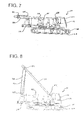
- FIG. 2 is a left side elevational view of the partially assembled crane with the mast in the stored position.
- the mast 34 supports the connection between the boom hoist rigging 38 and the boom pendants 36 at a location that is distanced from the axis of the boom 26 to optimize the forces in the boom pendants 36 and the boom hoist rigging 38.
- This arrangement also permits the boom hoist rigging 38 to impart a force having a component that is perpendicular to the axis of the boom 26. This force is transferred to the end of the boom 26 by the boom pendants 36.
- the boom hoist rope 40 and the boom pendants 36 are always in tension as long as the boom 26 is within the normal operating range of the crane 10.
- the mast 34 is always in compression as long as the boom 26 is within the normal operating range of the crane 10.
- a boom backstop 48 is provided to prevent the boom 26 from exceeding a safe operating angle (see FIG. 1).
- the mast 34 remains connected to the upper works 12 during transport of the partially disassemble crane 10 from one job site to another.
- the mast 34 is a large and heavy component, it is advantages to keep the mast 34 assembled to the crane 10. This also avoids the need to disassemble the boom hoist rigging 38 from between the mast 34 and the upper works 12. Nevertheless, it is necessary to position the mast 34 in a collapsed, horizontal position on top of the upper works 12 for transport. Orienting the mast 34 in this position allows the overall height and length of the partially disassembled crane 10 to be reduced so as to avoid most overhead obstacles and reduce the length of the transport vehicle required. Moreover, storing the mast 34 onto the rearward portion of the upper works 12 allows the weight of the mast to be more evenly distributed between the front and rear axles of the transport vehicle (not shown). This is an important consideration when highway limits on vehicle-axle loads must be observed.
- the mast raise cylinder 88 is retracted so as to rotate the mast raising yoke 66 to the stored position (i.e., 0°).
- the forward arm 76 of the mast raising yoke 66 is disposed approximately 20° above horizontal.
- the front engagement slot 80 on the forward arm 76 engages the lifting pin 84 on the leg 62 of the mast 34 when the mast 34 is at a mast angle of 160° (i.e., is 20° above horizontal).
- the mast raise cylinder 88 is preferably fully extended so as to place the mast raising yoke 66 at an angle of 115°.
- the mast raising yoke 66 serves as a backstop for the mast 34 to prevent the mast 34 from accidentally rotating back past vertical and collapsing onto the back of the upper works 12. This is particularly important when assembling components close to the crane 10, such as the crawlers 24, because the mast 34 must be positioned very close to vertical (i.e., a mast angle of 90°).
- the mast 34 can be very unstable when in a nearly vertical position.
- the mast 34 when the mast 34 is between 115° and 90°, the mast 34 must be controlled by using the mast raising yoke 66 in conjunction with the boom hoist rigging 38.
- boom hoist rigging 38 is extended too quickly relative to the rotation of the mast raising yoke 66 (and the motion of the mast 34), then too much slack may be created in the boom hoist rope 40, which may then tangle with other crane components or become fouled in the sheave assemblies 42, 44, or which may allow the boom hoist rope 40 to unspool from the boom hoist drum 46.
- the boom hoist rigging 38 is extended to slowly relative to the rotation of the mast raising yoke 66, then the mast 34 may collapse in response to loads applied thereto by the boom hoist rigging 38 and the mast raising yoke 66.
- precise control of the boom hoist rigging 38 and the mast cylinder is particularly important when the mast 34 is near vertical or in the fully forward position (and very unstable).
Abstract
Description
- The present application relates to construction equipment, such as cranes. In particular, the present application relates to a crane having several unique and inventive aspects, such as a self-raising mast, a hydraulic circuit for raising the mast, and a microprocessor-based controller for controlling the mast raising procedure. The present application also relates to a method of self-raising the mast and assembling the crane.
- Construction equipment, such as cranes or excavators, must often be moved from one job site to another. Moving a crane or an excavator can be a formidable task when the machine is large and heavy. For example, highway limits on vehicle-axle loads must be observed, and overhead obstacles can dictate long, inconvenient routings to the job site.
- One solution to improving the mobility of large construction machines, such as cranes, is to disassemble them into smaller, more easily handled components. The separate components can then be transported to the new job site where they are reassembled.
- The typical practice has been to use an assist crane to disassemble the crane into the separate components. The assist crane is then used to load the components onto their respective transport trailers. Once at the new job site, another assist crane is used to unload the components and reassemble the crane. As the components for a large crane can weigh as much as 80,000 Ibs., the capacity of the assist crane required represents a very significant transport expense.
- As a result, designers have attempted to develop self-handling systems for assembling and disassembling cranes. The majority of the self-handling systems developed thus far have been directed to smaller cranes that only need to be disassembled into a few components.
- The development of self-handling systems for larger cranes, however, has met with limited success. One reason for this is that larger cranes need to be disassembled into numerous components, thus requiring time-consuming disassembly and reassembly procedures. For example, a large capacity crane typically uses a complicated and cumbersome rigging system to control the angle of the boom. Boom rigging system components such as the equalizer, the mast, and wire rope rigging are heavy and difficult to disassemble for transport.
Another reason for the limited success of prior art self-assembling cranes is that they typically rely on additional crane components that are used only for assembling and disassembling the crane. For example, some self-assembling cranes require additional wire rope guides and sheaves on the boom butt so that a load hoist line can be used with the boom butt to lift various crane components during the assembly process. - An example of a prior art method for assembling and disassembling a typical large capacity crawler crane is disclosed in U.S. Patent No. 5,484,069, titled "Process For Self-Disassembling A Crawler Crane" ("the '069 patent"). In particular, this patent is directed to a type of crawler crane having a mast that is supported by a backhitch.
- Another example of a prior art method for assembling and disassembling a different type of crawler crane is disclosed in U.S. Patent No. 6,062,405, titled "Hydraulic Boom Hoist Cylinder Crane" ("the '405 patent"). This patent is directed to a type of crane that utilizes hydraulic cylinders to control the angle of the boom.
- The '069 patent and the '405 patent are both examples of self-assembling cranes that require the use of the boom butt to lift and position components for assembly on to the crane. As a consequence, additional sheaves must be included on the boom butt for the self-assembling procedure. It is therefore desirable to provide a crane and method of self-assembly which eliminates, or at least reduces, the use of the boom butt during the self-assembling procedure.
- In addition to the above, some types of cranes utilize a moving or live mast. A crane having a moving or live mast is connected directly to the boom by one or more boom pendants. The boom angle is controlled by boom hoist rigging, which is connected between the mast and the upper works of the crane. The mast and the boom move together as the boom angle is changed. The mast must typically be disconnected from the boom and stored horizontally on top of the crane for transport between job sites. Moreover, the masts on these types of cranes are often very long and heavy, and are consequently difficult to handle during the assembly process. It is therefore desirable to provide a crane having a self-raising mast. It is also desirable to provide a system and method of controlling the mast self-raising procedure that is safe, efficient and easy to implement.
- In preferred aspects, the present invention comprises a crane having an upper works rotatably mounted on a lower works, a boom pivotally mounted on the upper works, a mast pivotally mounted on the upper works and pendantly connected to the boom, and boom hoist rigging connected to the mast for controlling the angle of the boom. The invention further comprises a self-raising mast assembly for controlling the position of the mast when the mast is not connected to the boom. The self-raising mast assembly comprises a mast raising yoke, a hydraulic mast raise cylinder, and a hydraulic system.
- The mast raising yoke is pivotally connected to the upper works and preferably has an axis of rotation that is aligned with the axis of rotation of the mast. The mast raising yoke is configured to engage and support the mast when the mast is not within the mast operating range, and is disengaged from the mast when the mast is within the mast operating range, the mast being supportable by the boom hoist rigging when the mast is within the mast operating range.
- The hydraulic mast raise cylinder is pivotally connected between the upper works and the mast raising yoke. The hydraulic mast raise cylinder is extendable and retractable so as to rotate the mast raising yoke. The hydraulic system controls the extension and retraction of the hydraulic mast raise cylinder.
- The preferred method of self-raising the mast comprises the steps of first engaging the mast with the mast raising yoke when the mast is in a rearwardly extending stored position on a rearward portion of the upper works, then extending the mast raise cylinder to rotate the mast raising yoke in a first direction so as to pivot the mast upwardly from the stored position to a forwardly leaning position. When the mast is in the forwardly leaning position, the mast is then supported with the boom hoist rigging, while the mast raise cylinder is retracted to rotate the mast raising yoke in a second direction so as to disengage said mast raising yoke from the mast. The boom hoist rigging is then extended to lower the mast towards a forwardly extending fully forward position in front of the upper works, where it is then engaged by the mast raising yoke. The mast raise cylinder is then extended to rotate the mast raising yoke in the first direction so as to pivot the mast downwardly to the fully forward position. The mast can then be connected to the boom.
- The self-raising mast assembly and method permits the mast to be raised and lowered during the assembly process without the need for a separate crane, and overcomes many of the problems identified above. In particular, the self-raising mast assembly and method permits the mast to be raised from and lowered to a stored position on the rearward portion of the upper works. The assembly and method also permits the mast to be raised from and lowered to a fully forward position in front of the upper works. Moreover, the assembly and method permits the mast to be used for lifting and assembling crane components during the crane self-assembly and self-disassembly process.
- These and other advantages, as well as the invention itself, will become apparent in the details of construction and operation as more fully described and claimed below. Moreover, it should be appreciated that several aspects of the invention can be used with other types of cranes, machines or equipment.
- FIG. 1 is a right side elevational view of a complete crane incorporating a self-raising mast made in accordance with the teachings of this invention.
- FIG. 2 is a left side elevational view of the partially assembled crane with the mast in the stored position.
- FIG. 3 is a partial sectional view of the crane taken along
line 3―3 of FIG. 2 showing the location of the self-raising mast assemblies. - FIG. 4 is an enlarged view of detail A of FIG. 3 showing the principal components of a self-raising mast assembly.
- FIG. 5 is a partial sectional view of the crane taken along
line 5―5 of FIG. 3 showing the location of the self-raising mast assemblies. - FIG. 6 is an enlarged view of detail B of FIG. 5 showing the principal components of a self-raising mast assembly.
- FIGS. 7-10 are right side elevational views of the crane in sequential stages of the self-raising mast procedure.
- FIGS. 11-14 are schematic views of the self-raising mast assembly in sequential stages of the self-raising mast procedure.
- FIGS. 15-16 are right side elevational views of the crane in sequential stages of the boom assembly.
- FIG. 17 is an isometric view of the crane upper works showing the mast being raised during the self-raising mast procedure.
- FIGS. 18 is a schematic of the hydraulic circuit that controls the self-raising mast assemblies.
- While the present invention will find application in all types of cranes or construction machines, the preferred embodiment of the invention is described in conjunction with the
crawler crane 10 of FIG. 1. Thecrawler crane 10 includes anupper works 12 having a rotatingbed 14 that is rotatably connected to a lower works 16 by aswing bearing 18. The lower works 16 includes acar body 20,counterweights 22, and two independently powered crawlers 24. - The upper works 12 includes a
boom 26 pivotally connected to the upper works 12. Theboom 26 comprises aboom top 28 and atapered boom butt 30. Theboom 26 may also include one or more boom inserts 32 connected between theboom top 28 and theboom butt 30 to increase the overall length of theboom 26. Amast 34 is pivotally connected to the upper works 12. Theboom 26 is connected to themast 34 by one ormore boom pendants 36. - The angle of the
boom 26 is controlled by boom hoist rigging 38 connected between theupper works 12 and themast 34. As best seen in FIG. 17, the boom hoist rigging 38 comprises a boom hoistrope 40 that passes (reeved) around asheave assembly 42 on the upper end of themast 34 and asheave assembly 44 on the rear end of theupper works 12. One end of the boom hoistrope 40 is typically anchored to theupper works 12, while the other end is anchored to and wrapped around the boom hoistdrum 46. - The
mast 34 supports the connection between the boom hoist rigging 38 and theboom pendants 36 at a location that is distanced from the axis of theboom 26 to optimize the forces in theboom pendants 36 and the boom hoist rigging 38. This arrangement also permits the boom hoist rigging 38 to impart a force having a component that is perpendicular to the axis of theboom 26. This force is transferred to the end of theboom 26 by theboom pendants 36. Because the weight of theboom 26 is significantly greater than the weight of themast 34 and the boom hoist rigging 38, the boom hoistrope 40 and theboom pendants 36 are always in tension as long as theboom 26 is within the normal operating range of thecrane 10. Conversely, themast 34 is always in compression as long as theboom 26 is within the normal operating range of thecrane 10. Aboom backstop 48 is provided to prevent theboom 26 from exceeding a safe operating angle (see FIG. 1). - Rotation of the boom hoist
drum 46 in one direction (e.g., clockwise) will retract the boom hoistrope 40, thereby shortening the length of the boom hoist rigging 38 and causing the upper end of themast 34 to be pulled towards the rear of theupper works 12. This in turn raises the end of the boom 26 (i.e., increases the boom angle). Likewise, rotation of the boom hoistdrum 46 in the opposite direction (e.g., counter-clockwise) will pay out the boom hoistrope 40, thereby increasing the length of the boom hoist rigging 38 and allowing the upper end of themast 34 to be pulled away from rear of theupper works 12 by the weight of theboom 26. This action results in the lowering of the end of the boom 26 (i.e., decreases the boom angle). - The upper works 12 further includes one or more load hoist
lines 50 for lifting loads. Each load hoistline 50 is passed (reeved) around a load hoistline drum 52 supported on therotating bed 14 of theupper works 12. The load hoist line drums 52 are rotated to either pay out or retrieve the load hoistlines 50. The load hoistlines 50 are reeved around a plurality of boom top sheaves 54 located at the upper end of theboom top 28. The boom may also include one or more wire rope guides 56 attached to upper surface of theboom 26 to prevent the load hoistlines 50 from interfering with the lattice structure of theboom 26. A hook block (not shown) is typically attached to each load hoistline 50. - As best seen in FIG. 17, the
upper works 12 further includes apower plant 58, such as a diesel engine, and a counterweight assembly 22 (see FIG. 1). Thepower plant 58 supplies power for the various mechanical and hydraulic operations of thecrane 10, including movement of thecrawlers 24, rotation of therotating bed 14, rotation of the load hoist line drums 52, and rotation of the boom hoistdrum 46. Operation of the various functions of thecrane 10 is controlled from the operator'scab 60. - In the preferred embodiment shown, the
mast 34 is comprised of a steel frame having spaced apartrectangular legs 62. Themast 34 should not interfere with the operation of the load hoistlines 50 or theboom backstop 48. In addition, themast 34 should be configured so as to permit themast 34 to be lowered to an approximately horizontal stored position on top of theupper works 12 when thecrane 10 has been disassembled for transport, as shown in FIG. 2. This permits the overall height of the disassembledcrane 10 to be minimized so that highway height restrictions will not be violated during transport to and from the job site. As will be explained below, themast 34 is ordinarily not disassembled from thecrane 10 during transport. Themast 34 should also be configured so as to permit themast 34 to be lowered to an approximately horizontal fully forward position in front of theupper works 12. As will be explained below, it is desirable to lower themast 34 to the fully forward position to permit access to the upper end of themast 34 from the ground. - The
crane 10 of the preferred embodiment also comprises a pair of self-raisingmast assemblies 64 for raising and lower themast 34 during the assembling and disassembling of thecrane 10. As best seen in FIGS. 2-6, the self-raisingmast assemblies 64 each comprise amast raising yoke 66 pivotally supported by amast support frame 68 on either side of theupper works 12. The lower end of eachleg 62 of themast 34 is likewise supported by themast support frame 68. These components are preferably arranged so that themast 34 and themast raising yoke 66 have the same axis ofrotation 70 about the upper works 12. However, it should be noted that it is not necessary for the axis of rotation of themast raising yoke 66 to be coincident with the axis of rotation of themast 34. As best seen in FIG. 17, eachmast support frame 68 of the preferred embodiment comprises a pair ofvertical walls 72 that are disposed on each side of theleg 62 of themast 34. Themast raising yokes 66 are disposed along the inside of the mast support frame 68 (i.e., to the inside of thelegs 62 of the mast 34) (see FIG. 3). Eachleg 62 of themast 34 is supported by asupport pin 74 that extends through thevertical walls 72 of eachmast support frame 68. Themast raising yoke 66 is likewise supported by thesupport pin 74. - As best seen in FIG. 6, each
mast raising yoke 66 comprises aforward arm 76 and arearward arm 78. Theforward arm 76 and therearward arm 78 each comprise anengagement slot engagement slots lifting pin 84 on the inside surface of eachleg 62 of themast 34. In the preferred embodiment, theengagement slot 80 on theforward arm 76 and theengagement slot 82 on therearward arm 76 are separated by an angle of 160° about the axis ofrotation 70, said angle being measured along an arc above thesupport pin 74. In other words, if themast raising yoke 66 is oriented so that therearward arm 76 is disposed horizontally (i.e., parallel to the ground) and towards the rear of the crane 10 (i.e., rearwardly from the axis of rotation 70), then theforward arm 76 will be disposed towards the front of the crane 10 (i.e., forwardly from the axis of rotation 70) and at an angle of 20° above horizontal. - Each self-raising
mast assembly 64 further comprises alever arm 86 that is pivotally connected to thesupport pin 74 so as to be pivotal about the axis ofrotation 70. Thelever arm 86 is welded or otherwise fastened to themast raising yoke 66 so that thelever arm 86 and themast raising yoke 66 rotate about the axis ofrotation 70 as a unitary component. In other words, thelever arm 86 and themast raising yoke 66 rotate together. In the preferred embodiment shown, thelever arm 86 is a sub-component of themast raising yoke 66. - Each self-raising
mast assembly 64 further comprises a hydraulicmast raise cylinder 88 that is connected to an end of thelever arm 86. In particular, the upper end of the mast raise cylinder 88 (i.e., the piston rod) is connected to an end of thelever arm 86, and the lower end of the mast raise cylinder 88 (i.e., the bore) is connected to the upper works 12. As best seen in FIG. 6, themast raise cylinder 88 is arranged so that extension or contraction thereof will cause thelever arm 86, and in turn themast raising yoke 66, to rotate (i.e., pivot) about the axis ofrotation 70. As will be discussed in greater detail below, themast raise cylinder 88 and thelever arm 86 are preferably configured so that extension or contraction of themast raise cylinder 88 will rotate themast raising yoke 66 through an angle of approximately 115°. For example, when themast raise cylinder 88 is fully contracted, therearward arm 76 will be disposed horizontally (i.e., parallel to the ground) and towards the rear of thecrane 10. When themast raise cylinder 88 is fully extended, then therearward arm 76 will be disposed towards the front of thecrane 10 at an angle of 65° above horizontal. The extension and retraction of the mast raisecylinders 88 is controlled by a hydraulic circuit (to be described below). - The preferred method of self-assembling the
crawler crane 10 is best seen by referring to FIGS. 7-16 and the description above. - Referring to FIG. 7, the disassembled
crawler crane 10 is delivered to the job site on a transport trailer (not shown). Additional components, such as theboom top 28, boom inserts 32, and thecounterweights 22 are delivered on separate transport trailers (not shown) prior to their assembly to thecrane 10. Although in the preferred embodiment shown, thecrawlers 24 remain assembled to thecrane 10 during transport between job sites, these components may be delivered separately and assembled to thecrane 10 during the self-assembly process. A method and apparatus for assembling thecrawlers 24 to thecar body 20 are disclosed in U.S. Patent No. 5,427,256, titled "Crane Upper Works To Lower Works Alignment System". Another method of assembling thecrawlers 24 to thecar body 20 is disclosed in U.S. Patent No. 5,823,279, titled "Carbody To Crawler Connection". - As best seen in FIGS. 5 and 7, the
mast 34 remains connected to theupper works 12 during transport of the partially disassemblecrane 10 from one job site to another. As explained above, because themast 34 is a large and heavy component, it is advantages to keep themast 34 assembled to thecrane 10. This also avoids the need to disassemble the boom hoist rigging 38 from between themast 34 and theupper works 12. Nevertheless, it is necessary to position themast 34 in a collapsed, horizontal position on top of theupper works 12 for transport. Orienting themast 34 in this position allows the overall height and length of the partially disassembledcrane 10 to be reduced so as to avoid most overhead obstacles and reduce the length of the transport vehicle required. Moreover, storing themast 34 onto the rearward portion of theupper works 12 allows the weight of the mast to be more evenly distributed between the front and rear axles of the transport vehicle (not shown). This is an important consideration when highway limits on vehicle-axle loads must be observed. - The preferred method of self-raising the
mast 34 is best seen by referring to FIGS. 6-16 and the description above of the self-raisingmast assemblies 64. As best seen in FIGS. 6 and 7, when themast 34 is stored on the rearward portion of theupper works 12, the liftingpin 84 on the inside of eachleg 62 of themast 34 is disposed within therear engagement slot 82 on therearward arm 76 of themast raising yoke 66. Preferably, the liftingpin 84 is not resting directly on the bottom surface of therear engagement slot 82. This prevents themast 34, which may be subjected to movement or vibration during transport, from impacting themast raising yoke 66. - As best seen in FIG. 6, the
rearward arm 76 of themast raising yoke 66 is oriented approximately horizontal. This is referred to as the stored position for themast raising yoke 66. More specifically, the center of therear engagement slot 82 on therearward arm 76 is at approximately the same elevation (or slightly below) as the axis ofrotation 70 of themast 34. For the purpose of this description of the mast self-raising procedure, the orientation ofmast raising yoke 66 and themast 34 will be described in angles measured from a horizontal line extending rearwardly from the axis ofrotation 70. Themast raising yoke 66, when in the stored position, is therefore defined as being oriented at 0°. Themast 34, when in the stored position, is likewise defined as being oriented at 0°. When themast raising yoke 66 is in the stored position (i.e., at 0°), themast raise cylinder 88 is fully retracted. The relative positions of themast 34, themast raising yoke 66, and themast raise cylinder 88, when in the stored position, are also shown in the schematic of FIG. 11. - Of course, it should be noted that if the axis of rotation of the
mast raising yoke 66 is not coincident with the axis of rotation of themast 34, then the relative angles of these components might differ. For example, if the axis of themast raising yoke 66 is below the axis of rotation of themast 34, then therearward arm 76 might be oriented at an angle that is above horizontal when themast 34 is horizontal. - To initiate the mast self-raising procedure, the
mast raise cylinder 88 is extended so as to apply a force to the end of thelever arm 86, thereby causing themast raising yoke 66 to rotate in a clockwise direction (as viewed in FIG. 6). As therearward arm 76 of themast raising yoke 66 swings upward, therear engagement slot 82 engages the liftingpin 84 on themast 34. As best seen in FIG. 8, themast raise cylinder 88 is extended further to continue rotation of themast raising yoke 66 so as to pivot themast 34 up from the stored position and off of theupper works 12. As themast 34 is pivoted upwards, the boom hoist rigging 38 must simultaneously be lengthened to allow the upper end of themast 34 to freely move away from the rear end of theupper works 12. As explained above, the boom hoist rigging 38 is lengthened by rotating the boom hoistdrum 46 so as to pay out the boom hoistrope 40. As will be explained in greater detail below, a slight tension is maintained in the boom hoist rigging 38 so as to maintain control of themast 34. Tension is also maintained in the boom hoist rigging 38 so as to, for example, maintain proper spooling of the boom hoistrope 40 on the boom hoistdrum 46. It should be noted that FIG. 8 shows themast 34 and themast raising yoke 66 both at an angle of approximately 45°. - As shown in FIG. 9, extension of the
mast raise cylinder 88 is continued until themast 34 is pivoted past vertical and reaches a mast angle of approximately 115°. At a mast angle of 115°, the weight and the location of the center of gravity of themast 34 are sufficient to maintain themast 34 in a forward leaning orientation. In other words, the boom hoist rigging 38 can safely support themast 34 once themast 34 has reached a mast angle of 115°. Although this angle is considered to be the upper end of the safe operating range for themast 34 while using only the boom hoist rigging 38, it should be appreciated that themast 34 may be used above this range by utilizing the boom hoist rigging 38 in conjunction with themast raising yoke 66. In other words, and as will be explained below, themast 34 can be operated at angles between 90° and 115° by using the boom hoist rigging 38 together with themast raising yoke 66. The relative positions of themast 34, themast raising yoke 66, and themast raise cylinder 88, in this position, are also shown in the schematic of FIG. 12. - Of course, it should be noted that as the
mast 34 approaches vertical, it can become unstable, and may move unpredictably in response to wind loads or vibrations from crane machinery. Thus, it is very important that tension be maintained in the boom hoist rigging 38 as themast 34 approaches vertical. In other words, as themast raising yoke 66 is applying a force to themast 34 in one direction (i.e., pushing themast 34 towards the front of the crane 10), the boom hoist rigging 38 must simultaneously apply a force to themast 34 in the opposite direction (i.e., pulling themast 34 towards the rear of the crane 10). These two opposing forces stabilize themast 34. - Likewise, when the
mast 34 moves (i.e., pivoted) past vertical, forward pressure is maintained on themast 34 by themast raising yoke 66. This forward pressure keeps themast 34 from being tipped backwards by the weight of the boom hoist rigging 38 or any wind loads that may act on themast 34. As explained above, once the mast has reached a mast angle of 115°, the weight and the location of the center of gravity of themast 34 are sufficient to maintain themast 34 in a forward leaning orientation, and it is no longer necessary for themast raising yoke 66 to apply pressure to themast 34. - Beyond a mast angle of 115°, the
mast 34 is lowered towards the front of thecrane 10 by continuing to extend the boom hoist rigging 38. At this time, themast raise cylinder 88 is retracted so as to rotate themast raising yoke 66 back to the stored position (i.e., 0°). As themast raising yoke 66 is rotated back to the stored position (in a counter-clockwise direction as viewed in FIG. 9), therear engagement slot 82 disengages and moves away from the liftingpin 84 on theleg 62 of themast 34. In other words, themast 34 is no longer supported by themast raising yoke 66 once themast 34 moves beyond 115°. - As shown in FIG. 10, the
mast 34 is further lowered by extending the boom hoist rigging 38 until themast 34 reaches a mast angle of approximately 160° (i.e., 20° above horizontal as measured from the front of the crane 10). Beyond this angle, boom hoist rigging 38 can no longer safely support themast 34. This is because the direction of the force being applied to themast 34 by the boom hoist rigging 38 is nearly parallel with themast 34, and therefore does not apply a sufficient force perpendicular to themast 34 to keep themast 34 from continued rotation about the axis ofrotation 70. Moreover, the forces applied to themast 34 by the boom hoist rigging 38 at these angles may cause themast 34 to buckle. - Although 160° is considered to be the lower end of the safe operating range for the
mast 34 while using only the boom hoist rigging 38, it should be appreciated that themast 34 may be used below this range by utilizing themast raising yoke 66, either alone or in conjunction with the boom hoist rigging 38. In other words, themast 34 can be operated at angles between 160° and 180° by using themast raising yoke 66. - As the mast approaches a mast angle of 160°, the
mast raise cylinder 88 is retracted so as to rotate themast raising yoke 66 to the stored position (i.e., 0°). As explained above, when themast raising yoke 66 of the preferred embodiment is in tile stored position (see FIG. 6), theforward arm 76 of themast raising yoke 66 is disposed approximately 20° above horizontal. In this position, thefront engagement slot 80 on theforward arm 76 engages the liftingpin 84 on theleg 62 of themast 34 when themast 34 is at a mast angle of 160° (i.e., is 20° above horizontal). In other words, themast raising yoke 66 is positioned so as to support themast 34 when themast 34 reaches the lower end of the range wherein it can be supported by the boom hoist rigging 38 alone. The relative positions of themast 34, themast raising yoke 66, and themast raise cylinder 88, in this position, are also shown in the schematic of FIG. 13. Of course, these angles may be different if the center of rotation of themast raising yoke 66 is not coincident with the center of rotation of themast 34. - To lower the
mast 34 further (i.e., beyond a mast angle of 160°), themast raise cylinder 88 is extended to rotate the mast raising yoke 66 (in a clockwise direction as viewed in FIG. 10) and thereby lower theforward arm 76. Because the boom hoist rigging 38 is nearly parallel with themast 34, the weight of themast 34 is fully supported by themast raising yoke 66. However, the boom hoist rigging 38 must still be extended to permit themast 34 to be lowered by themast raising yoke 66. - In the preferred method of self-assembling the
crane 10, themast 34 is lowered to a mast angle of approximately 177° (see the schematic of FIG. 14) by extending themast raise cylinder 88. At this angle, the end of themast 34 is low enough to the ground to allow the rigging of a load hoistline 50 through thesheave assembly 42 on the end of themast 34. Once a load hoistline 50 has been rigged, themast 34 is then raised back up to a mast angle of 160° (i.e., more than 20° above horizontal) (see FIG. 10) by contracting themast raise cylinder 88. Once themast 34 has been raised above a mast angle of 160°, then the boom hoist rigging 38 alone can be used to control the angle of themast 34. - With the load hoist
line 50 rigged to themast 34, themast 34 can be used to lift and position additional crane components to thecrane 10. For example, thecrawlers 24, if not previously assembled to thecrane 10, can be lifted, positioned and assembled to the crane. Likewise, thecounterweights 22 can be assembled to thecrane 10 at this time. As shown sequentially in FIGS. 15 and 16, themast 34 can also be used to assemble theboom butt 30, the boom inserts 32 and theboom top 28 to theupper works 12 of thecrane 10. - While using the
mast 34 to assemble additional crane components, themast raise cylinder 88 is preferably fully extended so as to place themast raising yoke 66 at an angle of 115°. When oriented at this angle, themast raising yoke 66 serves as a backstop for themast 34 to prevent themast 34 from accidentally rotating back past vertical and collapsing onto the back of theupper works 12. This is particularly important when assembling components close to thecrane 10, such as thecrawlers 24, because themast 34 must be positioned very close to vertical (i.e., a mast angle of 90°). As previously explained, themast 34 can be very unstable when in a nearly vertical position. In addition, when themast 34 is between 115° and 90°, themast 34 must be controlled by using themast raising yoke 66 in conjunction with the boom hoist rigging 38. - Once the
boom 26 and other crane components have been assembled to thecrane 10, themast 34 is lowered down towards the front of thecrane 10 and on top of theboom 26 for final rigging. Using the same procedure as described above, themast raise cylinder 88 and themast raising yoke 66 are used to lower themast 34 when the mast angle is greater than 160° (i.e., less than 20° above horizontal). With themast 34 resting on top of theboom 26, the load hoistline 50 can be reeved about thesheaves 54 at the end of theboom top 28, and theboom pendants 36 can be likewise connected thereto. - Once finally rigging of the
boom 26 is complete, then themast raise cylinder 88 and themast raising yoke 66 are used to raise themast 34 above a mast angle of 160° (i.e., more than 20° above horizontal). Above this mast angle, themast 34 is raised and controlled by the boom hoist rigging 38 so as to raise theboom 26 off of the ground and place thecrane 10 into operational mode (as shown in FIG. 1). At this time, themast raise cylinder 88 is contracted so as to return themast raising yoke 66 to the stored position. This preventsmast raising yoke 66 from interfering with the movement of themast 34 during normal crane operations. - Self-disassembly of the
crane 10 is accomplished by following the method described above in reverse order. - Although the
mast 34 was described above as having an operational range of between 90° and 180° (between 115° and 160° when using the boom hoist rigging 38 alone), it should be noted that this range was only applicable when using themast 34 during crane self-assembly and self-disassembly (e.g., when using themast 34 to lift and assemble crane components to the crane 10). As can be seen in FIG. 1, themast 34 has a different range of motion when connected to theboom 26. This is because theboom 26 applies a significant force to the end of themast 34 that is opposite to the force that is applied to themast 34 by the boom hoist rigging 38. Thus, themast 34 is stable as long as theboom 26 is within the normal boom operating range. - Likewise, it should be apparent that the various angles discussed above are dependent on the geometry of the
crane 10 and the components thereof. Thus, cranes having different geometries or different components may require a mast raising cylinder having a different configuration, or a mast cylinder with a different stroke length. Such changes or modifications should be within the skill of those skilled in the art of cranes and related machinery. - Although the above-described method and the specific operations therein can be manually controlled and coordinated by the crane operator, some of these operations are preferably performed or assisted by a microprocessor-based controller (i.e., computer) (not shown) on the
crane 10. In particular, it can be very difficult to control both themast raise cylinder 88 and the boom hoist rigging 38 during the mast self-raising procedure. For example, and as described above, when raising themast 34 from the stored position, the operator must manipulate a first control to extend themast raise cylinder 88 and rotate themast raising yoke 66. The operator must simultaneously manipulate a second control to extend the boom hoist rigging 38. If the boom hoist rigging 38 is extended too quickly relative to the rotation of the mast raising yoke 66 (and the motion of the mast 34), then too much slack may be created in the boom hoistrope 40, which may then tangle with other crane components or become fouled in thesheave assemblies rope 40 to unspool from the boom hoistdrum 46. On the other hand, if the boom hoist rigging 38 is extended to slowly relative to the rotation of themast raising yoke 66, then themast 34 may collapse in response to loads applied thereto by the boom hoist rigging 38 and themast raising yoke 66. Moreover, and as explained above, precise control of the boom hoist rigging 38 and the mast cylinder is particularly important when themast 34 is near vertical or in the fully forward position (and very unstable). - In addition to the above, the operator may forget to perform certain steps in the mast self-raising procedure. For example, the operator may forget to place the
mast raising yoke 66 into the stored position before lowering themast 34 past the lower end of the operating range (i.e., below a mast angle of 160°). If so, then themast 34 may become unstable and fall to the ground as it nears horizontal. The operator may also forget to place themast raising yoke 66 into the mast backstop position (i.e., 115°) while using themast 34 for crane assembly. Thus, it is preferable that at least some of the operations performed during the mast self-raising procedure be performed or assisted by a microprocessor-based controller or computer. - As shown schematically in FIG. 18, the mast raise
cylinders 88 of the self-raisingmast assemblies 64 utilize a closed loop hydraulic system. This closed loop system is, however, hydraulically connected to the load hoist pump 90 (i.e., the hydraulic pump used to rotate the load hoist drum), which supplies hydraulic pressure thereto. The microprocessor-based controller is connected to the load hoist pump 90, the boom hoistpump 92, load pins 94 attached to each of the mast raisecylinders 88, thecontrol valve 96 and thepressure transducer 98. The controller can receive electrical signals from each of the load pins 94, thepressure transducer 98, themast angle indicator 100 and the operator'scontrol handle 102. The electrical signals from the load pins 94 are proportional to the mast loading on each mast raisecylinder 88. The electrical signal from thepressure transducer 98 is proportional to the hydraulic pressure generated by the load hoist pump 90. The electrical signals from themast angle indicator 100 and the control handle 102 are proportional to mast angle and handle position, respectively. The controller can source electrical signals that control the flow output of the load hoist pump 90 and the position of the control valve 102.Software that is resident in the controller runs a routine that semi-automates the mast raising and lowering operation via the boom hoistpump 92, the load hoist pump 90 and thecontrol valve 96. The mast raising and lowering is commanded from the operator'scontrol handle 102. During the raising or lowering sequence the boom hoistrope 40 and the mast raisecylinders 88 must simultaneously (or alternately) restrain themast 34 from falling and/or lift it into position. - In the preferred method of self-raising the
mast 34, the crane operator uses the computer to place thecrane 10 into set-up mode the crane operator then initiates the mast self-raising procedure by depressing the operator control handle 102. In response thereto, the computer will then begin to simultaneously pay out the boom hoistrope 40 and extend the mast raisecylinders 88 so as to raise themast 34. - In the preferred method, the computer maintains a slight tension in the boom hoist rigging 38, which helps to maintain control of the
mast 34 during the self-raising procedure. Utilizing the electrical signals from the two load pins 94, themast angle indicator 100 and thepressure transducer 98, flow from the load hoist pump 90 and the boom hoistpump 92 are controlled during the raise / lower operations to maintain the proper restraining and lifting load combinations between the boom hoistrope 40 and the mast raisecylinders 88. - Electrical signals from the
mast angle indicator 100 and the operator's control handle 102 are used to position the mast raisecylinders 88, and in turn themast raising yoke 66, in the proper orientation so as to receive themast 34 as it is lowered towards the full-forward position (i.e., beyond a mast angle of 160°), or as it is raised back towards vertical. In other words, if thecrane 10 is in "set-up" mode, then the computer will monitor the angle of themast 34 and coordinate the boom hoist rigging 38 and the self-raisingmast assemblies 64 so as to safely maintain control of themast 34 at all times during the mast self-raising procedure. - Additional sensors, such as pressure and speed sensors, may also be used to monitor the boom hoist rope tension and speed to provide additional monitoring mechanisms to ensure
safe mast 34 self-raising and operating procedures. - It should be appreciated that the apparatus and methods of the present invention are capable of being incorporated in the form of a variety of embodiments, only a few of which have been illustrated and described above. The invention may be embodied in other forms without departing from its spirit or essential characteristics. The described embodiments are to be considered in all respects only as illustrative and not restrictive, and the scope of the invention is, therefore, indicated by the appended claims rather than by the foregoing description. All changes which come within the meaning and range of equivalency of the claims are to be embraced within their scope.
Claims (32)
- A crane having an upper works rotatably mounted on a lower works and a boom pivotally mounted on the upper works, said boom being supported by boom hoist rigging and a mast pivotally connected to the upper works, said crane further having a self-raising mast assembly for controlling the position of the mast when said mast is not connected to the boom, said self-raising mast assembly comprising:a) a mast raising yoke pivotally connected to the upper works and having an axis of rotation, said mast raising yoke being configured to engage and support said mast when said mast is not supportable by said boom hoist rigging, and disengaged from said mast when said mast is supportable by said boom hoist rigging;b) a hydraulic mast raise cylinder pivotally connected between the upper works and said mast raising yoke, said hydraulic mast raise cylinder being extendable and retractable so as to rotate said mast raising yoke about said axis of rotation; andc) a hydraulic system for controlling the extension and retraction of said hydraulic mast raise cylinder.
- The crane according to claim 1 wherein said mast raising yoke comprises a rearward arm and a forward arm, said rearward arm being configured to engage and support said mast when said mast is between an approximately horizontal stored position towards a rearward portion of the upper works and an approximately vertical position, said forward arm being configured to engage and support said mast when said mast is near a horizontal position towards a forward portion of the crane.
- The crane according to claim 2 wherein said rearward arm and said forward arm each comprise an engagement member configured to engage a lifting member on the mast, the engagement member on the rearward arm being engaged by said lifting member when said mast is between the stored position and the approximately vertical position, the engagement member on the forward arm being engaged by the lifting member when said mast is near the horizontal position towards the forward portion of the crane.
- The crane according to claim 2 wherein said self-raising mast assembly comprises a pair of self-raising mast assemblies, each self-raising mast assembly being positioned to engage a leg of said mast.
- The crane according to claim 2 wherein said mast is pivotal through an angle of approximately 180°.
- The crane according to claim 2 wherein said mast raising yoke further comprises a lever arm pivotally connected to said mast raise cylinder.
- The crane according to claim 1 further comprising a microprocessor-based controller for coordinating the extension and contraction of the hydraulic mast raise cylinder with extension and contraction of the boom hoist rigging.
- The crane according to claim 7 wherein the microprocessor-based controller maintains a proper balance of forces in the boom hoist rigging and on the mast.
- A crane having an upper works rotatably mounted on a lower works and a boom pivotally mounted on the upper works, said boom being supported by boom hoist rigging and a moving mast pivotally connected to the upper works, said boom hoist rigging being connected between a rearward portion of said upper works and an upper end of said mast, and boom pendants being connected between the upper end of said mast and said boom, wherein said crane further comprises self-raising mast assembly for raising and lowering the mast when said mast is not connected to the boom and is not supportable by the boom hoist rigging, said self-raising mast assembly comprising:a) a mast raising yoke pivotally connected to the upper works and having an axis of rotation, said mast raising yoke having a rearward arm configured to engage and support said mast when said mast is between an approximately horizontal stored position towards the rearward portion of the upper works and an approximately vertical position, said rearward arm being disengaged from said mast when said mast is supported by said boom hoist rigging;b) a hydraulic mast raise cylinder pivotally connected between the upper works and said mast raising yoke, said hydraulic mast raise cylinder being extendable and retractable so as to rotate said mast raising yoke about said axis of rotation; andc) a hydraulic system for controlling the extension and retraction of said hydraulic mast raise cylinder.
- The crane according to claim 9 wherein said mast raising yoke further comprises a forward arm, said forward arm being configured to engage and support said mast when said mast is near a horizontal position towards a forward portion of the crane, said forward arm being disengaged from said mast when said mast is supported by said boom hoist rigging.
- The crane according to claim 10 wherein said rearward arm and said forward arm each comprise an engagement slot configured to engage a lifting pin on the mast, the engagement slot on the rearward arm being engaged by said lifting pin when said mast is between the stored position and the approximately vertical position, the engagement slot on the forward arm being engaged by the lifting pin when said mast is near the horizontal position towards a forward portion of the crane.
- The crane according to claim 11 wherein said self-raising mast assembly comprises a pair of self-raising mast assemblies, each self-raising mast assembly being positioned to engage a leg of said mast.
- The crane according to claim 11 wherein said mast raising yoke further comprises a lever arm pivotally connected to said mast raise cylinder.
- The crane according to claim 11 wherein said mast raising yoke is pivotal between a stored position and a mast backstop position, said rearward arm being generally horizontal when the mast raising yoke is in the stored position and generally vertical when the mast raising yoke is in the backstop position, said mast raising yoke being pivotal between the stored position and the mast backstop position by extension and contraction of the hydraulic mast raise cylinder.
- The crane according to claim 14 wherein, when said mast raising yoke is in the mast backstop position, the rearward arm prevents said mast from falling onto the rearward portion of the upper works.
- The crane according to claim 14 wherein, when said mast raising mast raising yoke is in the stored position, the forward arm prevents said mast from falling when said mast is near the horizontal position towards the forward portion of the crane.
- The crane according to claim 11 wherein said mast is pivotal through an angle of approximately 180° when not connected to the boom.
- The crane according to claim 17 wherein the mast, when not connected to the boom, is supportable by the rearward arm of the mast raising yoke when the angle of the mast is between approximately 0° and 115° as measured from the stored position, is supportable by the boom hoist rigging when the angle of the mast is between approximately 115° and 160°, and is supportable by the forward arm of the mast raising yoke when the angle of the mast is between approximately 160° and 180°.
- The crane according to claim 11 wherein the engagement slot on said rearward arm and the engagement slot on said forward arm are separated by an angle of approximately 160°, said angle being measured about the axis of rotation of said mast raising yoke.
- The crane according to claim 9 further comprising a microprocessor-based controller for coordinating the extension and contraction of the hydraulic mast raise cylinder with extension and contraction of the boom hoist rigging.
- The crane according to claim 20 wherein the microprocessor-based controller maintains a proper balance of forces in the boom hoist rigging and on said mast when said mast is not connected to the boom.
- A crane having an upper works rotatably mounted on a lower works and a boom pivotally mounted on the upper works, said boom being supported by boom hoist rigging and a moving mast pivotally connected to the upper works, said boom hoist rigging being connected between a rearward portion of said upper works and an upper end of said mast, and boom pendants being connected between the upper end of said mast and said boom, wherein said crane further comprises self-raising mast assembly for raising and lowering the mast when said mast is not connected to the boom and is not supportable by the boom hoist rigging, said self-raising mast assembly comprising:a) a mast raising yoke pivotally connected to the upper works and having an axis of rotation that is coincident with the pivotal connection of the mast to the upper works, said mast raising yoke having a rearward arm and a forward arm, said rearward arm being configured to engage and support said mast when said mast is between an approximately horizontal stored position toward the rearward portion of the upper works and an approximately vertical position, said forward arm being configured to engage and support said mast when said mast is near a horizontal position towards a forward portion of the crane, said rearward arm and said forward arm being disengageable from said mast when said mast is supported by said boom hoist rigging;b) a hydraulic mast raise cylinder pivotally connected between the upper works and said mast raising yoke, said hydraulic mast raise cylinder being extendable and retractable so as to rotate said mast raising yoke, the mast being raised or lowered by the rotation of said mast raising yoke when said mast is engaged by said rearward arm or said forward arm;c) a hydraulic system for controlling the extension and retraction of said hydraulic mast raise cylinder; andd) a microprocessor-based controller for controlling said hydraulic system, the control of said hydraulic system being coordinated with extension or contraction of the boom hoist rigging.
- The crane according to claim 22 wherein said rearward arm and said forward arm each comprise an engagement slot configured to engage a lifting pin on the mast, the engagement slot on the rearward arm being engaged by said lifting pin when said mast is between the stored position and the approximately vertical position, the engagement slot on the forward arm being engaged by the lifting pin when said mast is near the horizontal position towards the forward portion of the crane.
- The crane according to claim 22 wherein said mast raising yoke further comprises a lever arm pivotally connected to said mast raise cylinder.
- The crane according to claim 22 wherein said mast raising yoke is pivotal between a stored position and a mast backstop position, said rearward arm being generally horizontal when the mast raising yoke is in the stored position and generally vertical when the mast raising yoke is in the backstop position, said mast raising yoke being pivotal between the stored position and the mast backstop position by extension and contraction of the hydraulic mast raise cylinder.
- The crane according to claim 25 wherein, when said mast raising yoke is in the mast backstop position, the rearward arm prevents said mast from falling on to the rearward portion of the upper works, and further wherein, when said mast raising mast raising yoke is in the stored position, the forward arm prevents said mast from falling when said mast is near the horizontal position towards the forward portion of the crane.
- The crane according to claim 22 wherein the microprocessor-based controller is connected to a load-pin on said mast raise cylinder, said load pin providing an electrical signal to said microprocessor-based controller that is proportional to a load applied to the mast raise cylinder by said mast when said mast is engaged by said rearward arm or said forward arm.
- The crane according to claim 22 wherein the hydraulic system comprises a closed loop hydraulic system, said closed loop hydraulic system being hydraulically connected to a load hoist pump through a control valve, said control valve regulating a hydraulic pressure in the closed loop hydraulic system in response to electrical signals received from the microprocessor-based controller.
- A method of self-raising a mast for a crane having an upper works rotatably mounted on a lower works and a boom pivotally mounted on the upper works, said boom being supported by boom hoist rigging and a mast pivotally connected to the upper works, said crane further having a self-raising mast assembly for controlling the position of the mast when said mast is not connected to the boom and is not supportable by the boom hoist rigging, said self-raising mast assembly comprising a mast raising yoke pivotally connected to the upper works and having an axis of rotation, a hydraulic mast raise cylinder pivotally connected between the upper works and the mast raising yoke, and a hydraulic system for controlling the mast raise cylinder, said method comprising the sequential steps of:a) engaging the mast with the mast raising yoke when the mast is in a rearwardly extending stored position on a rearward portion of the upper works;b) extending the mast raise cylinder to rotate the mast raising yoke in a first direction so as to pivot the mast upwardly from the stored position to a forwardly leaning position;c) supporting the mast with the boom hoist rigging when the mast is in the forwardly leaning position;d) retracting the mast raise cylinder to rotate the mast raising yoke in a second direction so as to disengage said mast raising yoke from said mast when the mast is supported by the boom hoist rigging;e) extending the boom hoist rigging to lower the mast towards a forwardly extending fully forward position;f) engaging the mast with the mast raising yoke when the mast is near the fully forward position;g) extending the mast raise cylinder to rotate the mast raising yoke in the first direction so as to pivot the mast downwardly to the fully forward position; andh) connecting the mast to the boom.
- The method according to claim 29 wherein, when the mast is not connected to the boom, the mast is used to lift and assemble crane components to the crane.
- A method of self-raising a mast for a crane having an upper works rotatably mounted on a lower works and a boom pivotally mounted on the upper works, said boom being supported by boom hoist rigging and a mast pivotally connected to the upper works, said crane further having a self-raising mast assembly for controlling the position of the mast when said mast is not connected to the boom and is not supportable by the boom hoist rigging, said self-raising mast assembly comprising a mast raising yoke having a rear ward arm and a forward arm pivotally connected to the upper works and having an axis of rotation that is aligned with an axis of rotation of said mast, a hydraulic mast raise cylinder pivotally connected between the upper works and the mast raising yoke, and a hydraulic system for controlling the mast raise cylinder, said method comprising the sequential steps of:a) engaging the mast with the rearward arm of the mast raising yoke when the mast is in a rearwardly extending stored position on a rearward portion of the upper works, said rearward anti having an engagement slot that engages a lifting pin on the mast;b) extending the mast raise cylinder to rotate the mast raising yoke in a first direction so as to pivot the mast upwardly from the stored position to a forwardly leaning position;c) retracting the mast raise cylinder to rotate the mast raising yoke in a second direction so as to disengage the rearward arm of the mast raising yoke from said mast while the mast is in the forwardly leaning position;d) supporting the mast with the boom hoist rigging while the mast is in the forwardly leaning position;e) extending the boom hoist rigging to lower the mast towards a fully forward position;f) engaging the mast with the forward arm of the mast raising yoke when the mast is near the fully forward position, said forward arm having an engagement slot that engages the lifting pin on the mast;g) extending the mast raise cylinder to rotate the mast raising yoke in the first direction so as to pivot the mast downwardly to the fully forward position in front of the upper works;h) connecting the mast to the boom;i) retracting the mast raise cylinder to rotate the mast raising yoke in the second direction so as to pivot the mast upwardly from the fully forward position in front of the upper works; andj) retracting the boom hoist rigging to raise the mast and lift the boom into a crane operational range.
- The method according to claim 31 wherein, when the mast is not connected to the boom, the mast is used to lift and assemble crane components to the crane.
Applications Claiming Priority (2)
| Application Number | Priority Date | Filing Date | Title |
|---|---|---|---|
| US68563 | 2002-02-04 | ||
| US10/068,563 US6695158B2 (en) | 2002-02-04 | 2002-02-04 | Crane with self-raising mast |
Publications (3)
| Publication Number | Publication Date |
|---|---|
| EP1333004A2 true EP1333004A2 (en) | 2003-08-06 |
| EP1333004A3 EP1333004A3 (en) | 2005-06-08 |
| EP1333004B1 EP1333004B1 (en) | 2008-09-17 |
Family
ID=22083338
Family Applications (1)
| Application Number | Title | Priority Date | Filing Date |
|---|---|---|---|
| EP03250661A Expired - Lifetime EP1333004B1 (en) | 2002-02-04 | 2003-02-03 | Construction equipment with self-raising mast and method therefor |
Country Status (7)
| Country | Link |
|---|---|
| US (1) | US6695158B2 (en) |
| EP (1) | EP1333004B1 (en) |
| JP (1) | JP4455828B2 (en) |
| CN (1) | CN1332872C (en) |
| AT (1) | ATE408582T1 (en) |
| CA (1) | CA2418305C (en) |
| DE (1) | DE60323551D1 (en) |
Cited By (4)
| Publication number | Priority date | Publication date | Assignee | Title |
|---|---|---|---|---|
| EP1854759A2 (en) * | 2006-05-08 | 2007-11-14 | Kobelco Cranes Co., Ltd. | Boom hoisting device of a crane |
| EP1927571A2 (en) * | 2006-11-20 | 2008-06-04 | Kobelco Cranes Co., Ltd. | Crane |
| CN1891611B (en) * | 2005-07-06 | 2010-04-21 | 安徽柳工起重机有限公司 | Walk type crane |
| CN101259940B (en) * | 2007-03-07 | 2011-11-09 | 柳州欧维姆机械股份有限公司 | Large tonnage backstay multi-cable wind-rope simultaneously pretightening or releasing system and method thereof |
Families Citing this family (22)
| Publication number | Priority date | Publication date | Assignee | Title |
|---|---|---|---|---|
| US7385147B2 (en) * | 2002-03-13 | 2008-06-10 | Pioneer Energy Products, Llc | Articulated mast |
| US7688595B2 (en) * | 2002-03-13 | 2010-03-30 | Pioneer Energy Products, Llc | Shielded cable entry ports and assemblies |
| WO2004092490A1 (en) * | 2003-04-17 | 2004-10-28 | Silvatech Global Systems Ltd. | Swing boom pivot mechanism |
| CN100389057C (en) * | 2005-04-04 | 2008-05-21 | 山东鲁能光大重型机械设备有限公司 | All hydraulic caterpillar cranes |
| JP5007066B2 (en) * | 2006-04-21 | 2012-08-22 | 日立住友重機械建機クレーン株式会社 | crane |
| US7967158B2 (en) | 2006-10-27 | 2011-06-28 | Manitowoc Crane Companies, Llc | Mobile lift crane with variable position counterweight |
| JP4829763B2 (en) * | 2006-12-07 | 2011-12-07 | 日立住友重機械建機クレーン株式会社 | Crane safety equipment |
| JP2008143627A (en) * | 2006-12-07 | 2008-06-26 | Hitachi Sumitomo Heavy Industries Construction Crane Co Ltd | Safety device of crane |
| BRPI0807513B1 (en) * | 2007-02-16 | 2019-10-22 | Itrec Bv | hoisting crane and vessel. |
| US7762412B2 (en) * | 2007-04-26 | 2010-07-27 | Manitowoc Crane Companies, Llc | Mast raising structure and process for high-capacity mobile lift crane |
| KR20100072246A (en) * | 2007-09-14 | 2010-06-30 | 굿크레인 코퍼레이션 | Motion compensation system |
| DE102009016082A1 (en) * | 2008-04-28 | 2009-10-29 | Stefan Leske | Device for safely transferring personnel or material from a ship-shaped object to a relatively moved object and ship with the device |
| DE102009020338B4 (en) * | 2009-05-07 | 2011-07-21 | Manitowoc Crane Group France Sas | Telescopic crane with self-assembling guying fixture and mounting method for a guying fixture |
| CN101618837B (en) * | 2009-07-21 | 2011-12-14 | 上海三一科技有限公司 | Installation method and device of caterpillar crane mast |
| US9278834B2 (en) * | 2009-08-06 | 2016-03-08 | Manitowoc Crane Group, LLC | Lift crane with moveable counterweight |
| EP2423149B1 (en) * | 2010-08-24 | 2016-11-23 | Manitowoc Crane Group France SAS | Mounting for an auxiliary lifting device on a mobile crane |
| US8936167B2 (en) * | 2010-12-17 | 2015-01-20 | Kobelco Cranes Co., Ltd. | Crane |
| DE102011122812A1 (en) * | 2011-05-09 | 2012-11-15 | Liebherr-Werk Ehingen Gmbh | Method for assembling a mobile crane and mobile crane |
| US10183848B2 (en) | 2014-01-27 | 2019-01-22 | Manitowoc Crane Companies, Llc | Height adjustment mechanism for an auxiliary member on a crane |
| WO2015112992A1 (en) * | 2014-01-27 | 2015-07-30 | Manitowoc Crane Companies, Llc | Lift crane with mast-raising mechanism |
| CN110255402B (en) | 2014-01-27 | 2022-02-18 | 马尼托瓦克起重机有限责任公司 | Hoisting crane with improved movable counterweight |
| NL2018544B1 (en) * | 2017-03-17 | 2018-09-24 | Hermitage Family Office Sarl | Collapsible mast of a yacht |
Citations (4)
| Publication number | Priority date | Publication date | Assignee | Title |
|---|---|---|---|---|
| US2813636A (en) * | 1956-04-05 | 1957-11-19 | Wellman Mfg Company | Locomotive crane |
| US4081081A (en) * | 1975-10-23 | 1978-03-28 | The Manitowoc Company, Inc. | Demountable gantry, boom hoist and counterweight |
| US5240129A (en) * | 1990-06-04 | 1993-08-31 | Link-Belt Construction Equip. Co. | Heavy duty crane with self-retracting/erecting live mast |
| US6062405A (en) * | 1996-04-26 | 2000-05-16 | Manitowoc Crane Group, Inc. | Hydraulic boom hoist cylinder crane |
Family Cites Families (2)
| Publication number | Priority date | Publication date | Assignee | Title |
|---|---|---|---|---|
| US4579234A (en) * | 1984-03-16 | 1986-04-01 | American Hoist & Derrick Company | Self-erecting mobile crane |
| JP2911821B2 (en) * | 1996-06-12 | 1999-06-23 | 住友建機株式会社 | Crane load control device |
-
2002
- 2002-02-04 US US10/068,563 patent/US6695158B2/en not_active Expired - Lifetime
-
2003
- 2003-02-03 CA CA002418305A patent/CA2418305C/en not_active Expired - Fee Related
- 2003-02-03 AT AT03250661T patent/ATE408582T1/en not_active IP Right Cessation
- 2003-02-03 DE DE60323551T patent/DE60323551D1/en not_active Expired - Lifetime
- 2003-02-03 EP EP03250661A patent/EP1333004B1/en not_active Expired - Lifetime
- 2003-02-04 JP JP2003065740A patent/JP4455828B2/en not_active Expired - Fee Related
- 2003-02-08 CN CNB031043488A patent/CN1332872C/en not_active Expired - Fee Related
Patent Citations (4)
| Publication number | Priority date | Publication date | Assignee | Title |
|---|---|---|---|---|
| US2813636A (en) * | 1956-04-05 | 1957-11-19 | Wellman Mfg Company | Locomotive crane |
| US4081081A (en) * | 1975-10-23 | 1978-03-28 | The Manitowoc Company, Inc. | Demountable gantry, boom hoist and counterweight |
| US5240129A (en) * | 1990-06-04 | 1993-08-31 | Link-Belt Construction Equip. Co. | Heavy duty crane with self-retracting/erecting live mast |
| US6062405A (en) * | 1996-04-26 | 2000-05-16 | Manitowoc Crane Group, Inc. | Hydraulic boom hoist cylinder crane |
Cited By (7)
| Publication number | Priority date | Publication date | Assignee | Title |
|---|---|---|---|---|
| CN1891611B (en) * | 2005-07-06 | 2010-04-21 | 安徽柳工起重机有限公司 | Walk type crane |
| EP1854759A2 (en) * | 2006-05-08 | 2007-11-14 | Kobelco Cranes Co., Ltd. | Boom hoisting device of a crane |
| EP1854759A3 (en) * | 2006-05-08 | 2009-03-11 | Kobelco Cranes Co., Ltd. | Boom hoisting device of a crane |
| US7565982B2 (en) | 2006-05-08 | 2009-07-28 | Kobelco Cranes Co., Ltd. | Crane and boom hoisting device thereof |
| EP1927571A2 (en) * | 2006-11-20 | 2008-06-04 | Kobelco Cranes Co., Ltd. | Crane |
| EP1927571A3 (en) * | 2006-11-20 | 2009-04-22 | Kobelco Cranes Co., Ltd. | Crane |
| CN101259940B (en) * | 2007-03-07 | 2011-11-09 | 柳州欧维姆机械股份有限公司 | Large tonnage backstay multi-cable wind-rope simultaneously pretightening or releasing system and method thereof |
Also Published As
| Publication number | Publication date |
|---|---|
| CA2418305C (en) | 2007-05-29 |
| EP1333004B1 (en) | 2008-09-17 |
| ATE408582T1 (en) | 2008-10-15 |
| US6695158B2 (en) | 2004-02-24 |
| CN1332872C (en) | 2007-08-22 |
| US20030146181A1 (en) | 2003-08-07 |
| EP1333004A3 (en) | 2005-06-08 |
| CN1448332A (en) | 2003-10-15 |
| JP4455828B2 (en) | 2010-04-21 |
| DE60323551D1 (en) | 2008-10-30 |
| CA2418305A1 (en) | 2003-08-04 |
| JP2003252570A (en) | 2003-09-10 |
Similar Documents
| Publication | Publication Date | Title |
|---|---|---|
| US6695158B2 (en) | Crane with self-raising mast | |
| JP7168710B2 (en) | Lifting crane with movable counterweight | |
| JP7168718B2 (en) | Lift crane with improved movable counterweight | |
| US7762412B2 (en) | Mast raising structure and process for high-capacity mobile lift crane | |
| US7546928B2 (en) | Mobile lift crane with variable position counterweight | |
| US8397924B2 (en) | Drum frame system for cranes | |
| US6702132B1 (en) | Crane self-assembly system | |
| US9415980B2 (en) | Lift crane with mast-raising mechanism |
Legal Events
| Date | Code | Title | Description |
|---|---|---|---|
| PUAI | Public reference made under article 153(3) epc to a published international application that has entered the european phase |
Free format text: ORIGINAL CODE: 0009012 |
|
| AK | Designated contracting states |
Designated state(s): AT BE BG CH CY CZ DE DK EE ES FI FR GB GR HU IE IT LI LU MC NL PT SE SI SK TR |
|
| AX | Request for extension of the european patent |
Extension state: AL LT LV MK RO |
|
| PUAL | Search report despatched |
Free format text: ORIGINAL CODE: 0009013 |
|
| AK | Designated contracting states |
Kind code of ref document: A3 Designated state(s): AT BE BG CH CY CZ DE DK EE ES FI FR GB GR HU IE IT LI LU MC NL PT SE SI SK TR |
|
| AX | Request for extension of the european patent |
Extension state: AL LT LV MK RO |
|
| RAP1 | Party data changed (applicant data changed or rights of an application transferred) |
Owner name: MANITOWOC CRANE COMPANIES, INC. |
|
| 17P | Request for examination filed |
Effective date: 20051201 |
|
| AKX | Designation fees paid |
Designated state(s): AT DE FR GB |
|
| 17Q | First examination report despatched |
Effective date: 20060620 |
|
| GRAP | Despatch of communication of intention to grant a patent |
Free format text: ORIGINAL CODE: EPIDOSNIGR1 |
|
| RTI1 | Title (correction) |
Free format text: CONSTRUCTION EQUIPMENT WITH SELF-RAISING MAST AND METHOD THEREFOR |
|
| GRAS | Grant fee paid |
Free format text: ORIGINAL CODE: EPIDOSNIGR3 |
|
| GRAA | (expected) grant |
Free format text: ORIGINAL CODE: 0009210 |
|
| AK | Designated contracting states |
Kind code of ref document: B1 Designated state(s): AT DE FR GB |
|
| REG | Reference to a national code |
Ref country code: GB Ref legal event code: FG4D |
|
| REF | Corresponds to: |
Ref document number: 60323551 Country of ref document: DE Date of ref document: 20081030 Kind code of ref document: P |
|
| PG25 | Lapsed in a contracting state [announced via postgrant information from national office to epo] |
Ref country code: AT Free format text: LAPSE BECAUSE OF FAILURE TO SUBMIT A TRANSLATION OF THE DESCRIPTION OR TO PAY THE FEE WITHIN THE PRESCRIBED TIME-LIMIT Effective date: 20080917 |
|
| PGFP | Annual fee paid to national office [announced via postgrant information from national office to epo] |
Ref country code: GB Payment date: 20090106 Year of fee payment: 7 |
|
| PLBE | No opposition filed within time limit |
Free format text: ORIGINAL CODE: 0009261 |
|
| STAA | Information on the status of an ep patent application or granted ep patent |
Free format text: STATUS: NO OPPOSITION FILED WITHIN TIME LIMIT |
|
| 26N | No opposition filed |
Effective date: 20090618 |
|
| PGFP | Annual fee paid to national office [announced via postgrant information from national office to epo] |
Ref country code: FR Payment date: 20090206 Year of fee payment: 7 |
|
| GBPC | Gb: european patent ceased through non-payment of renewal fee |
Effective date: 20100203 |
|
| REG | Reference to a national code |
Ref country code: FR Ref legal event code: ST Effective date: 20101029 |
|
| PG25 | Lapsed in a contracting state [announced via postgrant information from national office to epo] |
Ref country code: FR Free format text: LAPSE BECAUSE OF NON-PAYMENT OF DUE FEES Effective date: 20100301 |
|
| PG25 | Lapsed in a contracting state [announced via postgrant information from national office to epo] |
Ref country code: GB Free format text: LAPSE BECAUSE OF NON-PAYMENT OF DUE FEES Effective date: 20100203 |
|
| PGFP | Annual fee paid to national office [announced via postgrant information from national office to epo] |
Ref country code: DE Payment date: 20220217 Year of fee payment: 20 |
|
| REG | Reference to a national code |
Ref country code: DE Ref legal event code: R071 Ref document number: 60323551 Country of ref document: DE |