EP1332900A1 - Aérateur, notamment pour véhicule automobile - Google Patents
Aérateur, notamment pour véhicule automobile Download PDFInfo
- Publication number
- EP1332900A1 EP1332900A1 EP03290198A EP03290198A EP1332900A1 EP 1332900 A1 EP1332900 A1 EP 1332900A1 EP 03290198 A EP03290198 A EP 03290198A EP 03290198 A EP03290198 A EP 03290198A EP 1332900 A1 EP1332900 A1 EP 1332900A1
- Authority
- EP
- European Patent Office
- Prior art keywords
- cover
- disc
- cylindrical body
- transverse wall
- extreme
- Prior art date
- Legal status (The legal status is an assumption and is not a legal conclusion. Google has not performed a legal analysis and makes no representation as to the accuracy of the status listed.)
- Granted
Links
Images


Classifications
-
- B—PERFORMING OPERATIONS; TRANSPORTING
- B60—VEHICLES IN GENERAL
- B60H—ARRANGEMENTS OF HEATING, COOLING, VENTILATING OR OTHER AIR-TREATING DEVICES SPECIALLY ADAPTED FOR PASSENGER OR GOODS SPACES OF VEHICLES
- B60H1/00—Heating, cooling or ventilating devices
- B60H1/34—Nozzles; Air-diffusers
- B60H1/3407—Nozzles; Air-diffusers providing an air stream in a fixed direction, e.g. using a grid or porous panel
-
- B—PERFORMING OPERATIONS; TRANSPORTING
- B60—VEHICLES IN GENERAL
- B60H—ARRANGEMENTS OF HEATING, COOLING, VENTILATING OR OTHER AIR-TREATING DEVICES SPECIALLY ADAPTED FOR PASSENGER OR GOODS SPACES OF VEHICLES
- B60H1/00—Heating, cooling or ventilating devices
- B60H1/34—Nozzles; Air-diffusers
- B60H1/3414—Nozzles; Air-diffusers with means for adjusting the air stream direction
- B60H1/3435—Nozzles; Air-diffusers with means for adjusting the air stream direction using only a pivoting frame
-
- F—MECHANICAL ENGINEERING; LIGHTING; HEATING; WEAPONS; BLASTING
- F24—HEATING; RANGES; VENTILATING
- F24F—AIR-CONDITIONING; AIR-HUMIDIFICATION; VENTILATION; USE OF AIR CURRENTS FOR SCREENING
- F24F13/00—Details common to, or for air-conditioning, air-humidification, ventilation or use of air currents for screening
- F24F13/08—Air-flow control members, e.g. louvres, grilles, flaps or guide plates
- F24F13/10—Air-flow control members, e.g. louvres, grilles, flaps or guide plates movable, e.g. dampers
- F24F13/105—Air-flow control members, e.g. louvres, grilles, flaps or guide plates movable, e.g. dampers composed of diaphragms or segments
Definitions
- the present invention relates to an aerator, in particular for motor vehicle.
- the aerators of today's motor vehicles are complicated and expensive, especially when they allow precise adjustment of the flow rate of the air flow admitted into vehicles and direct this flow air in all directions.
- the present invention proposes to remedy these disadvantages and, to do this, it relates to an aerator, especially for a motor vehicle, which is characterized in that it includes a cylindrical body one end of which is provided of a transverse wall comprising lights separated by connecting bridges, and a cover comprising a perforated bottom which is provided with recesses separated by solid parts and which is situated in front of the transverse wall of the cylindrical body, the cover being rotatably mounted thereon and movable between a position extreme open in which the lights of the transverse wall of the cylindrical body are fully uncovered and a position extreme closed in which said lights are entirely sealed.
- This aerator has a particularly simple structure, which makes it easy to manufacture and at a low cost price.
- the rotational mounting of the cover on the cylindrical body also has the advantage of allowing precise adjustment of the air flow rate admitted in the vehicle.
- the cover comprises a skirt covering at least partially the cylindrical body while retaining members are respectively provided on the surfaces in look of the skirt and the cylindrical body to limit the angle of rotation of the cover to a predetermined range delimited by the extreme open and closed positions.
- the additional retaining members may include least a set consisting of a groove extending in a plane perpendicular to the axis of rotation of the hood and a stud making protrusion in the groove.
- the structure of these organs is particularly simple, which facilitates manufacturing operations while reducing costs.
- the groove is located on the skirt of the hood while the nipple is located on the cylindrical body.
- bottom recesses perforated cover have dimensions at most equal to those of lights of the transverse wall of the cylindrical body.
- the aerator according to the invention further comprises a disc which has parts perforated separated by solid parts and which is interposed between the transverse wall of the cylindrical body and the perforated bottom of the cover, the solid parts of the disc being entirely covered by the solid parts of the bottom of the hood when the latter is in the angular range bounded by the extreme position open and a central position equidistant from the extreme positions open and closed.
- the solid parts of the disc are also fully exposed when the hood is in the angular range bounded by the extreme closed position and the central position.
- the presence of the disc increases the dimensions of the openings in the transverse wall of the cylindrical body and introduce a greater volume of air into the passenger compartment when the hood is in its extreme open position.
- the perforated disc and the cover comprise additional coupling means designed so that the disc is integral in rotation with the cover when the latter is moved from its extreme open position to its central position or from its extreme position closed to its central position.
- Opening and closing the wall lights transverse of the cylindrical body can thus be ensured of gradually and depending on the angle of rotation of the cover, this which allows precise adjustment of the flow rate of the air flow admitted into the passenger compartment of the vehicle.
- the complementary coupling means include preferably a radial protuberance and a circular groove one located on the internal surface of the cover and the other on the disc, the protrusion protruding into the groove and coming in contact with one end of it during movement from the hood from its extreme open position to its central position or from its extreme position closed to its central position.
- the wall transverse of the cylindrical body and the disc have preferably additional stop devices preventing said disc to rotate with the cover when it is driven in rotation beyond its central position.
- these stop devices may include a circular recess and boss located one on the transverse wall of the cylindrical body and the other on the disc, the disc can not rotate when the boss is applied against one end of the recess.
- At least one of the solid parts of the bottom perforated cover has an inside-facing rim and intended to come into contact with one of the connecting bridges of the transverse wall of the cylindrical body or with one of the parts full of the disc, if it exists, when the cover reaches in its extreme open position.
- the cover cannot therefore rotate beyond this position when a rotational force continues to be exerted on it in the direction corresponding to the opening of the lights.
- an air deflector can be provided inside the cylindrical body, this deflector being mounted on a control rod axially passing through the wall transverse of the cylindrical body, the disc when it is present and the perforated bottom of the cover, and comprising a ball joint cooperating with a spherical surface located on the wall transverse of the cylindrical body.
- the air flow entering the vehicle interior can thus be oriented in all directions of space, which allows improve passenger comfort.
- the deflector comprises at minus two concentric cylindrical elements connected by radial spacers.
- the deflector may also include a central cylindrical element comprising an axial bore in which the rod is retained by snap-fastening.
- the perforated bottom of the hood is preferably externally provided with a grid-forming coating.
- the two shutters that can be seen in the drawings are for introducing air into a passenger compartment of a vehicle automobile.
- the shutter shown in Figures 1 to 3 includes everything first a cylindrical body 1, one end of which is provided a transverse wall 2 comprising lights 3 separated by connecting bridges 4.
- cover 5 comprising a perforated bottom 6 which is provided with recesses 7 separated by solid parts 8 and which is located in front of the transverse wall of the cylindrical body 1.
- the cover 5 includes a skirt 9 partially covering the body 1 and is rotatably mounted thereon, between an extreme position open (visible in Figure 2) in which the lights 3 are fully uncovered and an extreme closed position (visible on Figure 3) in which the lights 3 are completely closed.
- the recesses 7 in the bottom of the cover 5 have dimensions at most equal to those of lights 3 in order to avoid that air enters the passenger compartment when the hood is in its extreme closed position.
- Additional retaining members 10, 11 are respectively provided on the facing surfaces of the skirt 9 and the cylindrical body 1.
- these organs include three grooves in the inner surface of the hood skirt and three nipples 11 protruding from the outer surface of the body side wall 1.
- the grooves 10 are angularly equidistant and extend in a plane perpendicular to the axis of rotation of the cover.
- the nipples 11 are angularly equidistant and extend in a plane perpendicular to the longitudinal axis of the cylindrical body.
- the grooves 10 have, at one of their ends, an axial extension 12 opening on the side opposite the bottom 6 of the cover.
- the nipples 11 can of course be very easily inserted into their respective grooves.
- the length of the grooves 10 is fixed so that the angle of rotation of the cover 5 on the body cylindrical 1 is limited to a predetermined range whose ends define the extreme open and closed positions.
- the aerator which has just been described further comprises a air deflector 13 located inside the cylindrical body 1.
- the deflector 13 comprises a central cylindrical element 14, a intermediate cylindrical element 15 and a cylindrical element exterior 16.
- the central element 14 has an axial bore 17.
- the intermediate and external elements they are concentric and extend coaxially with the central element.
- the intermediate element 15 is connected to the central element 14 by radial spacers 18 while the external element 16 is connected to the intermediate element 15 by radial spacers 19 angularly offset with respect to the spacers 18.
- the deflector 13 is mounted on a control rod 20 axially passing through the transverse wall 2 of the cylindrical body 1 and the perforated bottom 6 of the cover 5.
- the rod 20 is retained by snap-fastening in the bore 17 of the central element 14 and comprises in its middle part a ball joint 21 cooperating on the one hand with a spherical surface 22 located on the external face of the transverse wall 2 of the cylindrical body and on the other hand with the internal face of the bottom 6 of the cover.
- the bottom 6 of the cover is provided on its face external of a frustoconical central orifice 24 through which the part 23 of rod 20 can be easily inclined relative to the axis longitudinal of the aerator in order to position the deflector in a predetermined position.
- the bottom 6 of the cover may be provided externally with a grid-forming coating 25, this coating being only partially shown in FIG. 1.
- the advantage of the grid coating is that it allows better diffusion of air at its outlet from the aerator and improve the aesthetics of the latter by concealing the lights 3 of the cylindrical body and the recesses 7 of the cover.
- the second shutter which will be described below comprises a disc 26 interposed between the transverse wall 2 of the cylindrical body and the perforated bottom 6 of the cover 5.
- the disc 26 has perforated parts 27 separated by solid parts 28 and whose dimensions are double those of these.
- the perforated parts 27 of the disc have dimensions identical or practically identical to those of lights 3 of the transverse wall 2 of the cylindrical body 1 and those of recesses 7 in the bottom of the cover 5.
- solid parts 28 they have dimensions identical or practically identical to those of the connecting bridges 4 of the transverse wall 2 of the cylindrical body 1 and to those of solid parts 8 of the bottom of the cover 5.
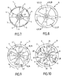
- the solid parts 28 of the disc are completely covered by the solid parts 8 of the bottom of the cover 5 when the latter is in the angular range delimited by its extreme open position visible in Figure 8 and its extreme central position which is equidistant from its extreme open and closed positions and which is visible in figure 9.
- the cover 5 has a protuberance on its internal surface radial 29 while the disc 26 has on its face turned towards the cover a circular groove 30 receiving the radial protuberance 29.
- the groove 30 has a predetermined length so that the radial protuberance 29 comes into contact with one of its ends while moving the cover from its extreme position open visible in FIG. 8 at its central position visible on Figure 9.
- the transverse wall 2 of the cylindrical body has, on its face facing the disc 26 a circular recess 31 while the disc 26 has on its face facing the cylindrical body a circular boss 32 housed in the circular recess 31.
- the recess 31 and the boss 32 are intended to prevent the disc 26 to rotate with the cover 5 when the latter is driven rotating beyond its central position. Their lengths respective are indeed chosen so that the boss 32 comes in against one end of the recess 31 and thus prevents the disc 26 to rotate with the cover when the latter, once in its central position, continues to be rotated towards its extreme closed position.
- the solid parts 8 of the bottom 6 of the cover have a flange 33 projecting along one of their radial sides.
- These flanges 33 are intended to come into contact with one of the radial sides of the solid parts of the disc 26 when the cover manages in its extreme open position and prevent the latter to rotate past this position.
- the aerator visible in Figures 4 to 10 also includes a air deflector 13 provided with a rod 20 axially passing through the transverse wall 2 of the body 1, the disc 26 and the bottom 6 of the cover 5.
- the ball joint 21 of the rod 20 again cooperates with the surface spherical 22 of the transverse wall 2 of the cylindrical body and the inner face of the bottom 6 of the cover.
- the disc 26 indeed has a central opening large enough that it can freely to cross.
- the bottom 6 of the cover 5 can be provided externally a coating forming a grid 25.
- the aerators just described are very easy to use.
- Bridges 4 are fully visible when the hood arrives in its middle position shown in Figure 9.
- the solid parts 28 are fully visible when the hood arrives in its extreme closed position visible in the figure 10.
- the cover first drives the disc 26 with it until let it come in its middle position. In this position, solid parts 28 of the disc remain visible and therefore overlap the connecting bridges 4 of the transverse wall 2 of the body 1.
Landscapes
- Engineering & Computer Science (AREA)
- Mechanical Engineering (AREA)
- Physics & Mathematics (AREA)
- Thermal Sciences (AREA)
- General Engineering & Computer Science (AREA)
- Combustion & Propulsion (AREA)
- Chemical & Material Sciences (AREA)
- Air-Flow Control Members (AREA)
- Ventilation (AREA)
- Preparation Of Compounds By Using Micro-Organisms (AREA)
- Medicines Containing Material From Animals Or Micro-Organisms (AREA)
- Air-Conditioning For Vehicles (AREA)
- Motor Or Generator Cooling System (AREA)
- Superstructure Of Vehicle (AREA)
Abstract
Description
- la figure 1 est une vue schématique éclatée d'un aérateur selon un premier mode de réalisation ;
- la figure 2 est une vue de dessus de cet aérateur dont le capot est en position extrême ouverte, le déflecteur d'air étant omis pour plus de clarté ;
- la figure 3 est une vue analogue à la figure 2, mais montrant le capot en position extrême fermée ;
- la figure 4 est une schématique éclatée d'un aérateur selon un deuxième mode de réalisation ;
- la figure 5 est une vue selon la ligne V-V de la figure 4 et montre la partie intérieure du capot ;
- la figure 6 est une vue selon la ligne VI-VI de la figure 4 et montre la face du disque qui est dirigée vers l'intérieur du capot ;
- la figure 7 est une vue de dessus du corps cylindrique de l'aérateur ;
- la figure 8 est une vue de dessus de l'aérateur visible sur la figure 4, mais dont le déflecteur d'air n'est pas représenté pour plus de clarté, les lumières de la paroi transversale du corps cylindrique étant entièrement découvertes.
- la figure 9 est une vue analogue à la figure 8, mais montre les lumières à moitié obturées ; et
- la figure 10 est une vue analogue à la figure 8, mais montre les lumières entièrement obturées.
Claims (15)
- Aérateur, notamment pour véhicule automobile, comprenant un corps (1) dont l'une des extrémités est pourvue d'une paroi transversale (2) comportant des lumières (3) séparées par des ponts de liaison (4), et un élément rotatif (5) comportant un fond perforé (6) qui est pourvu d'évidements (7) séparés par des parties pleines (8) et qui est situé devant la paroi transversale du corps (1), l'élément (5) étant monté sur ce dernier de façon à pouvoir être entraíné en rotation entre une position extrême ouverte dans laquelle les lumières (3) de la paroi transversale (2) du corps cylindrique (1) sont entièrement découvertes et une position extrême fermée dans laquelle lesdites lumières sont entièrement obturées, caractérisé en ce que le corps (1) est cylindrique et en ce que l'élément rotatif (5) est un capot comportant une jupe (9) recouvrant au moins partiellement le corps cylindrique (1), des organes de retenue (10, 11) complémentaires étant respectivement prévus sur les surfaces en regard de la jupe (9) et du corps cylindrique (1) pour limiter l'angle de rotation du capot (5) à une plage prédéterminée délimitée par les positions extrêmes ouverte et fermée.
- Aérateur selon la revendication 1, caractérisé en ce que les organes de retenue (10, 11) complémentaires comprennent au moins un ensemble constitué d'une rainure (10) s'étendant dans un plan perpendiculaire à l'axe de rotation du capot (5) et d'un téton (11) faisant saillie dans la rainure.
- Aérateur selon la revendication 2, caractérisé en ce que la rainure (10) est située sur la jupe (9) du capot (5) tandis que le téton est situé sur le corps cylindrique (1).
- Aérateur selon l'une quelconque des revendications 1 à 3, caractérisé en ce que les évidements (7) du fond perforé (6) du capot (5) ont des dimensions au plus égales à celles des lumières (3) de la paroi transversale (2) du corps cylindrique (1).
- Aérateur selon l'une quelconque des revendications 1 à 3, caractérisé en ce qu'il comprend en outre un disque (26) qui comporte des parties perforées (27) séparées par des parties pleines (28) et qui est interposé entre la paroi transversale (2) du corps cylindrique (1) et le fond perforé (6) du capot (5), les parties pleines (28) du disque (26) étant entièrement recouvertes par les parties pleines (8) du fond (6) du capot (5) lorsque celui-ci est dans la plage angulaire délimitée par la position extrême ouverte et une position centrale équidistante des positions extrêmes ouverte et fermée.
- Aérateur selon la revendication 5, caractérisé en ce que les parties pleines (28) du disque (26) sont entièrement découvertes lorsque le capot (5) est dans la plage angulaire délimitée par la position extrême fermée et la position centrale.
- Aérateur selon la revendication 5 ou 6, caractérisé en ce que le disque perforé (26) et le capot (5) comprennent des moyens d'accouplement (29, 30) complémentaires conçus de telle sorte que le disque (26) est solidaire en rotation du capot (5) lorsque celui-ci est déplacé de sa position extrême ouverte à sa position centrale ou de sa position extrême fermée à sa position centrale.
- Aérateur selon la revendication 7, caractérisé en ce que les moyens d'accouplement (29, 30) complémentaires comprennent une protubérance (29) radiale et une rainure circulaire (30) situées l'une sur la surface interne du capot (5) et l'autre sur le disque (26), la protubérance (29) faisant saillie dans la rainure (30) et venant en contact avec l'une des extrémités de celle-ci pendant le déplacement du capot (5) de sa position extrême ouverte à sa position centrale ou de sa position extrême fermée à sa position centrale.
- Aérateur selon l'une quelconque des revendications 5 à 8, caractérisé en ce que la paroi transversale (2) du corps cylindrique (1) et le disque (26) comportent des organes d'arrêt (31, 32) complémentaires empêchant ledit disque de tourner avec le capot (5) lorsque celui-ci est entraíné en rotation au-delà de sa position centrale.
- Aérateur selon la revendication 9, caractérisé en ce que les organes d'arrêt (31, 32) comprennent un renfoncement (31) et un bossage (32) circulaire et situés l'un sur la paroi transversale du corps cylindrique (1) et l'autre sur le disque (26), le disque (26) ne pouvant tourner lorsque le bossage (32) est appliqué contre l'une des extrémités du renfoncement (31).
- Aérateur selon l'une quelconque des revendications 1 à 10, caractérisé en ce que l'une au moins des parties pleines (8) du fond perforé (6) du capot (5) comporte un rebord (33) tourné vers l'intérieur et destiné à venir en contact avec l'un des ponts de liaison (4) de la paroi transversale (2) du corps cylindrique (1) ou avec l'une des parties pleines (28) du disque (26), si celui-ci existe, lorsque le capot (5) parvient dans sa position extrême ouverte.
- Aérateur selon l'une quelconque des revendications précédentes, caractérisé en ce qu'un déflecteur d'air (13) est prévu à l'intérieur du corps cylindrique (1), ce déflecteur étant monté sur une tige de commande (20) traversant axialement la paroi transversale (2) du corps cylindrique (1), le disque (26) lorsque celui-ci est présent et le fond perforé (6) du capot (5), et comportant une rotule (21) coopérant avec une surface sphérique (22) située sur la paroi transversale (2) du corps cylindrique (1).
- Aérateur selon la revendication 12, caractérisé en ce que le déflecteur (13) comprend au moins deux éléments cylindriques concentriques (15, 16) reliés par des entretoises radiales (18, 19).
- Aérateur selon la revendication 12 ou 13, caractérisé en ce que le déflecteur (13) comprend un élément cylindrique central (14) comportant un alésage axial (17) dans lequel la tige (20) est retenue par encliquetage.
- Aérateur selon l'une quelconque des revendications précédentes, caractérisé en ce que le fond perforé (6) du capot (5) est pourvu extérieurement d'un revêtement formant grille (25).
Applications Claiming Priority (2)
| Application Number | Priority Date | Filing Date | Title |
|---|---|---|---|
| FR0201094 | 2002-01-30 | ||
| FR0201094A FR2835219B1 (fr) | 2002-01-30 | 2002-01-30 | Aerateur, notamment pour vehicule automobile |
Publications (2)
| Publication Number | Publication Date |
|---|---|
| EP1332900A1 true EP1332900A1 (fr) | 2003-08-06 |
| EP1332900B1 EP1332900B1 (fr) | 2006-01-04 |
Family
ID=8871432
Family Applications (1)
| Application Number | Title | Priority Date | Filing Date |
|---|---|---|---|
| EP03290198A Expired - Lifetime EP1332900B1 (fr) | 2002-01-30 | 2003-01-27 | Aérateur, notamment pour véhicule automobile |
Country Status (4)
| Country | Link |
|---|---|
| EP (1) | EP1332900B1 (fr) |
| AT (1) | ATE314944T1 (fr) |
| DE (1) | DE60303100T2 (fr) |
| FR (1) | FR2835219B1 (fr) |
Cited By (5)
| Publication number | Priority date | Publication date | Assignee | Title |
|---|---|---|---|---|
| EP1418071A3 (fr) * | 2002-11-05 | 2004-06-16 | REUM GmbH & Co. Betriebs KG | Dispositif pour diriger l'air |
| EP1519119A3 (fr) * | 2003-09-23 | 2006-03-22 | Liebert Hiross S.p.A. | Volet notamment pour les installations de climatisation |
| FR2892342A1 (fr) * | 2005-10-21 | 2007-04-27 | Bourbon Automobile Soc Par Act | Dispositif permettant de commander l'ecoulement d'un fluide et d'orienter cet ecoulement dans une direction determinee |
| KR20190005265A (ko) * | 2017-07-05 | 2019-01-16 | 현대모비스 주식회사 | 차량용 에어벤트 |
| CN119175989A (zh) * | 2024-10-12 | 2024-12-24 | 中国第一汽车股份有限公司 | 一种可伸缩多功能出风口及汽车 |
Families Citing this family (7)
| Publication number | Priority date | Publication date | Assignee | Title |
|---|---|---|---|---|
| DE102005054295A1 (de) * | 2005-11-11 | 2007-05-16 | Behr Gmbh & Co Kg | Luftausströmer |
| DE102008033339A1 (de) * | 2008-07-16 | 2010-01-21 | Behr Gmbh & Co. Kg | Luftausströmer mit Drallströmung und gerichteter Strömung |
| DE102013213277A1 (de) * | 2013-07-05 | 2015-01-08 | Behr Gmbh & Co. Kg | Luftausströmer |
| DE102014210300A1 (de) * | 2014-05-30 | 2015-12-03 | MAHLE Behr GmbH & Co. KG | Luftausströmdüse |
| FR3062087B1 (fr) | 2017-01-20 | 2019-06-07 | Valeo Systemes Thermiques | Aerateur, notamment pour vehicule automobile |
| DE102017115012B3 (de) | 2017-07-05 | 2018-05-24 | Dr. Ing. H.C. F. Porsche Aktiengesellschaft | Belüftungskanal für eine Lüftungsvorrichtung eines Kraftfahrzeugs |
| JP6747469B2 (ja) * | 2017-07-25 | 2020-08-26 | 株式会社デンソー | 車両用空調ユニット |
Citations (5)
| Publication number | Priority date | Publication date | Assignee | Title |
|---|---|---|---|---|
| FR2245182A7 (fr) * | 1973-07-02 | 1975-04-18 | Happich Gmbh Gebr | |
| GB1436838A (en) * | 1972-02-29 | 1976-05-26 | Clear Hooters Ltd | Ventilating nozzle |
| EP0094479A2 (fr) * | 1982-05-15 | 1983-11-23 | Gebr. Happich GmbH | Aérateur sphérique pour véhicules |
| US5297989A (en) * | 1993-01-13 | 1994-03-29 | Bowles Fluidics Corporation | Nozzle for discharging air and method |
| FR2792256A1 (fr) * | 1999-04-16 | 2000-10-20 | 3 D Dev | Aerateur, notamment pour habitacle de vehicule automobile |
-
2002
- 2002-01-30 FR FR0201094A patent/FR2835219B1/fr not_active Expired - Fee Related
-
2003
- 2003-01-27 DE DE60303100T patent/DE60303100T2/de not_active Expired - Fee Related
- 2003-01-27 EP EP03290198A patent/EP1332900B1/fr not_active Expired - Lifetime
- 2003-01-27 AT AT03290198T patent/ATE314944T1/de not_active IP Right Cessation
Patent Citations (5)
| Publication number | Priority date | Publication date | Assignee | Title |
|---|---|---|---|---|
| GB1436838A (en) * | 1972-02-29 | 1976-05-26 | Clear Hooters Ltd | Ventilating nozzle |
| FR2245182A7 (fr) * | 1973-07-02 | 1975-04-18 | Happich Gmbh Gebr | |
| EP0094479A2 (fr) * | 1982-05-15 | 1983-11-23 | Gebr. Happich GmbH | Aérateur sphérique pour véhicules |
| US5297989A (en) * | 1993-01-13 | 1994-03-29 | Bowles Fluidics Corporation | Nozzle for discharging air and method |
| FR2792256A1 (fr) * | 1999-04-16 | 2000-10-20 | 3 D Dev | Aerateur, notamment pour habitacle de vehicule automobile |
Cited By (5)
| Publication number | Priority date | Publication date | Assignee | Title |
|---|---|---|---|---|
| EP1418071A3 (fr) * | 2002-11-05 | 2004-06-16 | REUM GmbH & Co. Betriebs KG | Dispositif pour diriger l'air |
| EP1519119A3 (fr) * | 2003-09-23 | 2006-03-22 | Liebert Hiross S.p.A. | Volet notamment pour les installations de climatisation |
| FR2892342A1 (fr) * | 2005-10-21 | 2007-04-27 | Bourbon Automobile Soc Par Act | Dispositif permettant de commander l'ecoulement d'un fluide et d'orienter cet ecoulement dans une direction determinee |
| KR20190005265A (ko) * | 2017-07-05 | 2019-01-16 | 현대모비스 주식회사 | 차량용 에어벤트 |
| CN119175989A (zh) * | 2024-10-12 | 2024-12-24 | 中国第一汽车股份有限公司 | 一种可伸缩多功能出风口及汽车 |
Also Published As
| Publication number | Publication date |
|---|---|
| DE60303100D1 (de) | 2006-03-30 |
| DE60303100T2 (de) | 2006-08-31 |
| EP1332900B1 (fr) | 2006-01-04 |
| FR2835219A1 (fr) | 2003-08-01 |
| FR2835219B1 (fr) | 2004-12-03 |
| ATE314944T1 (de) | 2006-02-15 |
Similar Documents
| Publication | Publication Date | Title |
|---|---|---|
| EP1332900B1 (fr) | Aérateur, notamment pour véhicule automobile | |
| WO2006048538A1 (fr) | Aerateur de systeme de ventilation de l'habitacle d'un vehicule | |
| EP3649000B1 (fr) | Volet d'obturation pour dispositif de régulation d'un flux d'air pour module de face avant pour véhicule automobile | |
| EP1886072A1 (fr) | Aerateur a reglage d orientation et de debit obtenu par rotation d un corps profile | |
| EP4255512A1 (fr) | Diffuseur se fixant sur une grille d'aeration pour la diffusion controlee d'un parfum d'ambiance | |
| FR2892993A1 (fr) | Dispositif aerodynamique pour un vehicule automobile et vehicule automobile comportant au moins un tel dispositif aerodynamique. | |
| EP1199197B1 (fr) | Dispositif de commande pour système de distribution d'un flux d'air dans un véhicule | |
| WO2005035336A1 (fr) | Obturateur pour partie creuse de vehicule automobile | |
| EP0873922B1 (fr) | Motoréducteur pour essuie-glace de véhicule automobile avec un conduit de liquide de nettoyage | |
| FR2809349A1 (fr) | Barillet d'aerateur pour vehicule automobile | |
| EP1162095A1 (fr) | Ensemble d'aérateur occultable pour véhicule automobile et équipement correspondant | |
| FR2625141A1 (fr) | Goulotte de remplissage de carburant equipee d'un dispositif de fermeture perfectionne commande de l'interieur du vehicule | |
| FR2791114A1 (fr) | Dispositif permettant de commander l'ecoulement d'un fluide et l'orientation de cet ecoulement | |
| FR2879510A1 (fr) | Dispositif de distribution d'air a volets independants | |
| FR3064660A1 (fr) | Dispositif de verrouillage pour couvercle de compartiment de rangement, compartiment de rangement associe et vehicule associe | |
| EP1705041B1 (fr) | Aérateur pour véhicule comprenant des ailettes pourvues chacune d'une bielle de commande actionnée par une molette | |
| FR3043361A1 (fr) | Dispositif d'aerateur pour vehicule automobile | |
| EP1300319A1 (fr) | Direction à crémaillère pour véhicule automobile | |
| EP0940294B1 (fr) | Dispositif d'étanchéité pour rétroviseur extérieur, en particulier de véhicule automobile | |
| EP1749682A1 (fr) | Aérateur, notamment pour automobile, comprenant des ailettes de réglage pivotantes montées sur un corps rotatif | |
| FR2521268A1 (fr) | Volet de dosage pour conduit de ventilation | |
| EP1690708B1 (fr) | Aérateur pour véhicule comprenant des ailettes portées par un corps cylindrique rotatif | |
| FR2600122A1 (fr) | Verin a actionnement rotatif, notamment pour la commande d'un volet interpose dans un circuit de climatisation d'un vehicule automobile | |
| FR2881993A1 (fr) | Aerateur a ailettes pivotantes et a ailettes rotatives pour vehicule, notamment pour automobile | |
| FR2827815A1 (fr) | Aerateur pour vehicule automobile |
Legal Events
| Date | Code | Title | Description |
|---|---|---|---|
| PUAI | Public reference made under article 153(3) epc to a published international application that has entered the european phase |
Free format text: ORIGINAL CODE: 0009012 |
|
| AK | Designated contracting states |
Designated state(s): AT BE BG CH CY CZ DE DK EE ES FI FR GB GR HU IE IT LI LU MC NL PT SE SI SK TR |
|
| AX | Request for extension of the european patent |
Extension state: AL LT LV MK RO |
|
| 17P | Request for examination filed |
Effective date: 20031021 |
|
| AKX | Designation fees paid |
Designated state(s): AT BE BG CH CY CZ DE DK EE ES FI FR GB GR HU IE IT LI LU MC NL PT SE SI SK TR |
|
| GRAP | Despatch of communication of intention to grant a patent |
Free format text: ORIGINAL CODE: EPIDOSNIGR1 |
|
| GRAS | Grant fee paid |
Free format text: ORIGINAL CODE: EPIDOSNIGR3 |
|
| GRAA | (expected) grant |
Free format text: ORIGINAL CODE: 0009210 |
|
| AK | Designated contracting states |
Kind code of ref document: B1 Designated state(s): AT BE BG CH CY CZ DE DK EE ES FI FR GB GR HU IE IT LI LU MC NL PT SE SI SK TR |
|
| PG25 | Lapsed in a contracting state [announced via postgrant information from national office to epo] |
Ref country code: IT Free format text: LAPSE BECAUSE OF FAILURE TO SUBMIT A TRANSLATION OF THE DESCRIPTION OR TO PAY THE FEE WITHIN THE PRESCRIBED TIME-LIMIT;WARNING: LAPSES OF ITALIAN PATENTS WITH EFFECTIVE DATE BEFORE 2007 MAY HAVE OCCURRED AT ANY TIME BEFORE 2007. THE CORRECT EFFECTIVE DATE MAY BE DIFFERENT FROM THE ONE RECORDED. Effective date: 20060104 Ref country code: SK Free format text: LAPSE BECAUSE OF FAILURE TO SUBMIT A TRANSLATION OF THE DESCRIPTION OR TO PAY THE FEE WITHIN THE PRESCRIBED TIME-LIMIT Effective date: 20060104 Ref country code: FI Free format text: LAPSE BECAUSE OF FAILURE TO SUBMIT A TRANSLATION OF THE DESCRIPTION OR TO PAY THE FEE WITHIN THE PRESCRIBED TIME-LIMIT Effective date: 20060104 Ref country code: SI Free format text: LAPSE BECAUSE OF FAILURE TO SUBMIT A TRANSLATION OF THE DESCRIPTION OR TO PAY THE FEE WITHIN THE PRESCRIBED TIME-LIMIT Effective date: 20060104 Ref country code: NL Free format text: LAPSE BECAUSE OF FAILURE TO SUBMIT A TRANSLATION OF THE DESCRIPTION OR TO PAY THE FEE WITHIN THE PRESCRIBED TIME-LIMIT Effective date: 20060104 Ref country code: IE Free format text: LAPSE BECAUSE OF FAILURE TO SUBMIT A TRANSLATION OF THE DESCRIPTION OR TO PAY THE FEE WITHIN THE PRESCRIBED TIME-LIMIT Effective date: 20060104 Ref country code: AT Free format text: LAPSE BECAUSE OF FAILURE TO SUBMIT A TRANSLATION OF THE DESCRIPTION OR TO PAY THE FEE WITHIN THE PRESCRIBED TIME-LIMIT Effective date: 20060104 Ref country code: GB Free format text: LAPSE BECAUSE OF FAILURE TO SUBMIT A TRANSLATION OF THE DESCRIPTION OR TO PAY THE FEE WITHIN THE PRESCRIBED TIME-LIMIT Effective date: 20060104 |
|
| REG | Reference to a national code |
Ref country code: GB Ref legal event code: FG4D Free format text: NOT ENGLISH |
|
| REG | Reference to a national code |
Ref country code: CH Ref legal event code: EP |
|
| PG25 | Lapsed in a contracting state [announced via postgrant information from national office to epo] |
Ref country code: MC Free format text: LAPSE BECAUSE OF NON-PAYMENT OF DUE FEES Effective date: 20060131 |
|
| REG | Reference to a national code |
Ref country code: IE Ref legal event code: FG4D Free format text: LANGUAGE OF EP DOCUMENT: FRENCH |
|
| PG25 | Lapsed in a contracting state [announced via postgrant information from national office to epo] |
Ref country code: LU Free format text: LAPSE BECAUSE OF NON-PAYMENT OF DUE FEES Effective date: 20060304 |
|
| REF | Corresponds to: |
Ref document number: 60303100 Country of ref document: DE Date of ref document: 20060330 Kind code of ref document: P |
|
| PG25 | Lapsed in a contracting state [announced via postgrant information from national office to epo] |
Ref country code: BG Free format text: LAPSE BECAUSE OF FAILURE TO SUBMIT A TRANSLATION OF THE DESCRIPTION OR TO PAY THE FEE WITHIN THE PRESCRIBED TIME-LIMIT Effective date: 20060404 Ref country code: DK Free format text: LAPSE BECAUSE OF FAILURE TO SUBMIT A TRANSLATION OF THE DESCRIPTION OR TO PAY THE FEE WITHIN THE PRESCRIBED TIME-LIMIT Effective date: 20060404 Ref country code: SE Free format text: LAPSE BECAUSE OF FAILURE TO SUBMIT A TRANSLATION OF THE DESCRIPTION OR TO PAY THE FEE WITHIN THE PRESCRIBED TIME-LIMIT Effective date: 20060404 |
|
| PG25 | Lapsed in a contracting state [announced via postgrant information from national office to epo] |
Ref country code: ES Free format text: LAPSE BECAUSE OF FAILURE TO SUBMIT A TRANSLATION OF THE DESCRIPTION OR TO PAY THE FEE WITHIN THE PRESCRIBED TIME-LIMIT Effective date: 20060415 |
|
| PG25 | Lapsed in a contracting state [announced via postgrant information from national office to epo] |
Ref country code: PT Free format text: LAPSE BECAUSE OF FAILURE TO SUBMIT A TRANSLATION OF THE DESCRIPTION OR TO PAY THE FEE WITHIN THE PRESCRIBED TIME-LIMIT Effective date: 20060605 |
|
| NLV1 | Nl: lapsed or annulled due to failure to fulfill the requirements of art. 29p and 29m of the patents act | ||
| GBV | Gb: ep patent (uk) treated as always having been void in accordance with gb section 77(7)/1977 [no translation filed] |
Effective date: 20060104 |
|
| REG | Reference to a national code |
Ref country code: IE Ref legal event code: FD4D |
|
| PLBE | No opposition filed within time limit |
Free format text: ORIGINAL CODE: 0009261 |
|
| STAA | Information on the status of an ep patent application or granted ep patent |
Free format text: STATUS: NO OPPOSITION FILED WITHIN TIME LIMIT |
|
| 26N | No opposition filed |
Effective date: 20061005 |
|
| PGFP | Annual fee paid to national office [announced via postgrant information from national office to epo] |
Ref country code: DE Payment date: 20070110 Year of fee payment: 5 |
|
| PG25 | Lapsed in a contracting state [announced via postgrant information from national office to epo] |
Ref country code: LI Free format text: LAPSE BECAUSE OF NON-PAYMENT OF DUE FEES Effective date: 20070131 Ref country code: CH Free format text: LAPSE BECAUSE OF NON-PAYMENT OF DUE FEES Effective date: 20070131 |
|
| PGFP | Annual fee paid to national office [announced via postgrant information from national office to epo] |
Ref country code: BE Payment date: 20070201 Year of fee payment: 5 |
|
| REG | Reference to a national code |
Ref country code: CH Ref legal event code: PL |
|
| PG25 | Lapsed in a contracting state [announced via postgrant information from national office to epo] |
Ref country code: GR Free format text: LAPSE BECAUSE OF FAILURE TO SUBMIT A TRANSLATION OF THE DESCRIPTION OR TO PAY THE FEE WITHIN THE PRESCRIBED TIME-LIMIT Effective date: 20060405 Ref country code: CZ Free format text: LAPSE BECAUSE OF FAILURE TO SUBMIT A TRANSLATION OF THE DESCRIPTION OR TO PAY THE FEE WITHIN THE PRESCRIBED TIME-LIMIT Effective date: 20060104 |
|
| PGFP | Annual fee paid to national office [announced via postgrant information from national office to epo] |
Ref country code: FR Payment date: 20070123 Year of fee payment: 5 |
|
| PG25 | Lapsed in a contracting state [announced via postgrant information from national office to epo] |
Ref country code: EE Free format text: LAPSE BECAUSE OF FAILURE TO SUBMIT A TRANSLATION OF THE DESCRIPTION OR TO PAY THE FEE WITHIN THE PRESCRIBED TIME-LIMIT Effective date: 20060104 |
|
| BERE | Be: lapsed |
Owner name: KEY PLASTICS INTERNATIONAL Effective date: 20080131 |
|
| PG25 | Lapsed in a contracting state [announced via postgrant information from national office to epo] |
Ref country code: HU Free format text: LAPSE BECAUSE OF FAILURE TO SUBMIT A TRANSLATION OF THE DESCRIPTION OR TO PAY THE FEE WITHIN THE PRESCRIBED TIME-LIMIT Effective date: 20060705 Ref country code: TR Free format text: LAPSE BECAUSE OF FAILURE TO SUBMIT A TRANSLATION OF THE DESCRIPTION OR TO PAY THE FEE WITHIN THE PRESCRIBED TIME-LIMIT Effective date: 20060104 |
|
| PG25 | Lapsed in a contracting state [announced via postgrant information from national office to epo] |
Ref country code: DE Free format text: LAPSE BECAUSE OF NON-PAYMENT OF DUE FEES Effective date: 20080801 |
|
| PG25 | Lapsed in a contracting state [announced via postgrant information from national office to epo] |
Ref country code: CY Free format text: LAPSE BECAUSE OF FAILURE TO SUBMIT A TRANSLATION OF THE DESCRIPTION OR TO PAY THE FEE WITHIN THE PRESCRIBED TIME-LIMIT Effective date: 20060104 |
|
| REG | Reference to a national code |
Ref country code: FR Ref legal event code: ST Effective date: 20081029 |
|
| PG25 | Lapsed in a contracting state [announced via postgrant information from national office to epo] |
Ref country code: BE Free format text: LAPSE BECAUSE OF NON-PAYMENT OF DUE FEES Effective date: 20080131 |
|
| PG25 | Lapsed in a contracting state [announced via postgrant information from national office to epo] |
Ref country code: FR Free format text: LAPSE BECAUSE OF NON-PAYMENT OF DUE FEES Effective date: 20080131 |