EP1332898A2 - Vorrichtung zur Luftverteilung im Innenraum eines Kraftfahrzeugs - Google Patents
Vorrichtung zur Luftverteilung im Innenraum eines Kraftfahrzeugs Download PDFInfo
- Publication number
- EP1332898A2 EP1332898A2 EP03001853A EP03001853A EP1332898A2 EP 1332898 A2 EP1332898 A2 EP 1332898A2 EP 03001853 A EP03001853 A EP 03001853A EP 03001853 A EP03001853 A EP 03001853A EP 1332898 A2 EP1332898 A2 EP 1332898A2
- Authority
- EP
- European Patent Office
- Prior art keywords
- housing
- elements
- shut
- air
- instrument panel
- Prior art date
- Legal status (The legal status is an assumption and is not a legal conclusion. Google has not performed a legal analysis and makes no representation as to the accuracy of the status listed.)
- Withdrawn
Links
Images


Classifications
-
- B—PERFORMING OPERATIONS; TRANSPORTING
- B60—VEHICLES IN GENERAL
- B60H—ARRANGEMENTS OF HEATING, COOLING, VENTILATING OR OTHER AIR-TREATING DEVICES SPECIALLY ADAPTED FOR PASSENGER OR GOODS SPACES OF VEHICLES
- B60H1/00—Heating, cooling or ventilating devices
- B60H1/00507—Details, e.g. mounting arrangements, desaeration devices
- B60H1/00514—Details of air conditioning housings
- B60H1/0055—Details of air conditioning housings the housing or parts thereof being integrated in other devices, e.g. dashboard
-
- B—PERFORMING OPERATIONS; TRANSPORTING
- B60—VEHICLES IN GENERAL
- B60H—ARRANGEMENTS OF HEATING, COOLING, VENTILATING OR OTHER AIR-TREATING DEVICES SPECIALLY ADAPTED FOR PASSENGER OR GOODS SPACES OF VEHICLES
- B60H1/00—Heating, cooling or ventilating devices
- B60H1/00507—Details, e.g. mounting arrangements, desaeration devices
- B60H1/00557—Details of ducts or cables
- B60H1/00564—Details of ducts or cables of air ducts
Definitions
- the invention relates to a device for air distribution in the interior of a motor vehicle.
- From DE 24 938 C2 is an arrangement of modules an air conditioner in a motor vehicle, in which for the purpose of easier installation a control box as a separate component in one Mounting opening of a dashboard is fitted.
- DE 26 48 663 A1 describes a ventilation device for an interior of a vehicle, which at minimal effort on adjusting devices without loss on adjustment options with various others Components of a dashboard combined to form a unit can be. These are in a distributor housing several flow paths provided.
- DE 199 09 663 A1 is a heating or air conditioning shown for a motor vehicle.
- This heater or Air conditioning system has a Heiltemper istsmodul and an air distribution module.
- the device according to the invention can be stored with those in the housing Shut off those air outlet openings be controlled by closing or opening, leading to the Heilausströmdüsen.
- This will allows, from a central point in the housing, where the actuators are housed, also removed from the housing mounted Heilausströmdüsen to control, and with very simple mechanical Means, namely the fasteners, which the actuators with the shut-off elements connect mechanically.
- This simple construction the device according to the invention thus causes despite their high functionality only very low cost.
- One for a large number of motor vehicles very well suitable development of the invention may consist in that at least two first Luftausströmdüsen in a central area of the instrument panel and at least two second air exhaust nozzles in the side End portions of the instrument panel arranged are.
- Fig. 1 shows an extremely schematic representation of a Instrument panel 1 one in its entirety not shown motor vehicle. Inside the instrument panel 1 is a device 2 for air distribution arranged in the interior of the motor vehicle, which optionally with an air conditioner, not shown can be connected.
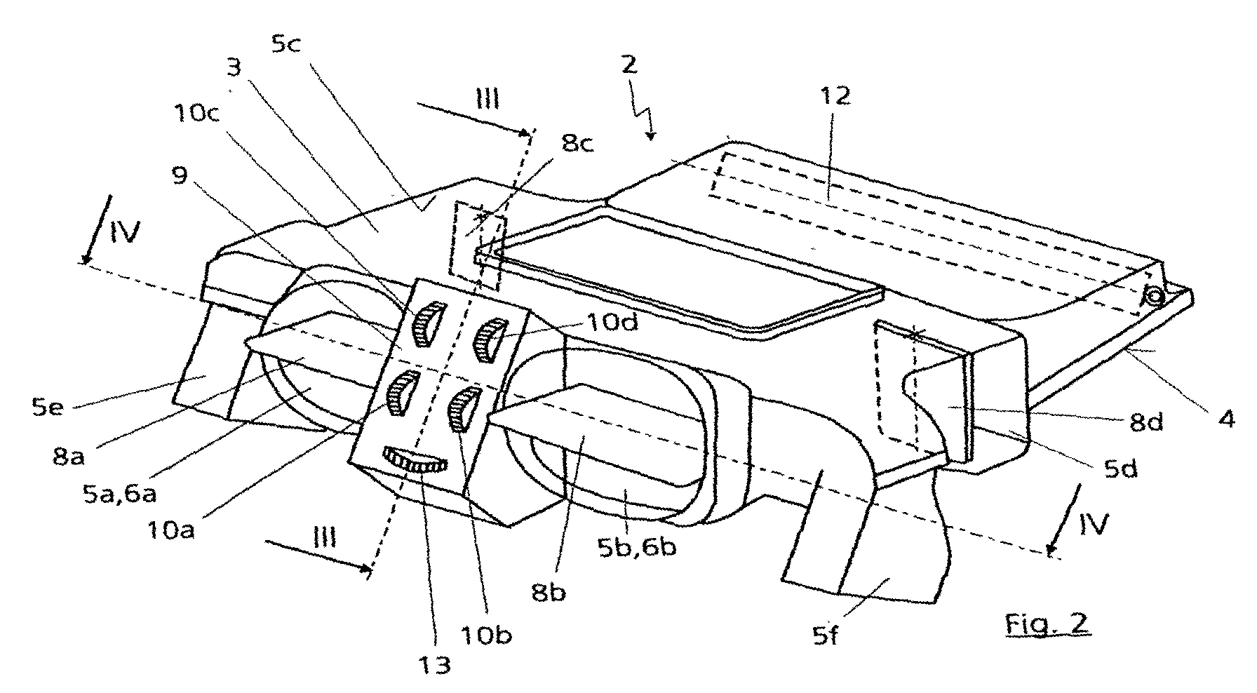
- the device 2 has an example of plastic existing housing 3 with one shown in Fig. 2 Air supply opening 4 and a total of six Air outlet openings 5a, 5b, 5c, 5d, 5e and 5f on.
- Air supply opening 4 is, for example, from an air conditioning box under it, an air conditioner, Air introduced into the housing 3.
- the two air outlet openings 5a and 5b are direct connected to Heilausströmdüsen 6a and 6b, which in a central area of the instrument panel 1, or fall with these Gutausströmdüsen 6a and 6b together.
- the two, respectively provided in a lateral region of the housing 3 Air outlet openings 5c and 5d over two independent air ducts 7 with Heilausströmdüsen 6c and 6d connected, which are in the two lateral end portions of the instrument panel 1 and thus spaced from the first Heilausströmdüsen 6 a and 6b are located.
- the air discharge nozzles 6a and 6b become due to their arrangement as Heilausströmdüsen and the air exhaust nozzles 6c and 6d as side exhaust nozzles designated.
- the air outlet openings 5e and 5f can be e.g. to a foot area, not shown in the front or rear interior of the motor vehicle lead, where also provided Heilausströmdüsen could be.
- the air outlet openings 5a, 5b, 5c and 5d by means of respective, in the present Fall as flaps trained shut-off 8a, 8b, 8c and 8d controllable, i. they can with the Shut-off elements 8a, 8b, 8c and 8d open or closed become.
- the shut-off elements 8a, 8b, 8c and 8d are in each case mounted in the housing 3.
- shut-off elements 8a, 8b, 8c and 8d are on a control panel 9 of the housing 3 four trained as a hand rotatable wheels
- Actuators 10a, 10b, 10c, 10d arranged, which with the respective shut-off elements 8a, 8b, 8c and 8d in detail in Figures 3 and 4 mechanical connecting elements 11a, 11b, 11c and 11d are connected.
- the actuators 10a, 10b, 10c, 10d are therefore likewise mounted in the housing 3.
- the actuating elements 10a, 10b, 10c, 10d is a central controller the Heilabströmö réelleen 5a, 5b, 5c and 5d or the Air exhaust nozzles 6a, 6b, 6c and 6d from the control panel. 9 out possible by the driver and it can otherwise Required actuators on the side Beerausströmdüsen 6c and 6d omitted.
- the housing 3 may be completely closed become.
- the two air outlet openings 5e and 5f may optionally also with shut-off elements and the same over Connecting elements controlling actuators be opened and closed.
- Such intended Actuators could also on the Control panel 9 may be arranged.
- shut-off 12 can also be on the control panel 9 arranged actuator 13 and a connected thereto Joining element 14 are controlled.
- the shut-off element 12 is a so-called cold air lowering possible, in which the over the air supply opening 4 in the housing 3 incoming air cold Fresh air can be added.
- Fig. 3 are two of the connecting elements, namely the connecting elements 11b and 11d shown. This are each designed as a linkage and on the one Side with the shut-off elements 8b and 8d and on the other side with the associated actuators 10b and 10d connected. In the present case are for the connection of the connecting elements 11b and 11d on the actuators 10b and 10d gears intended. Furthermore, in Fig. 3, the air supply opening 4 to the housing 3 and a fastener 15 recognizable, on which the housing 3, for example be attached to the instrument panel 1 can.
- shut-off 8a, 8b, 8e and 8f be provided, which then the Heilabströmö Stammen 5a, 5b, 5e and 5f, regardless of whether the housing 3 the Heilabströmö Stammen 5c and 5d or not.
- each two of the Heilausströmdüsen 6a and 6b and 6c and 6d a common Provide actuator 10a and 10c and on the Actuators 10b and 10d to dispense.
- the connecting elements could each 11a and 11b and 11c and 11d in pairs with the associated actuating elements 10a and 10c coupled his.
Landscapes
- Physics & Mathematics (AREA)
- Thermal Sciences (AREA)
- Engineering & Computer Science (AREA)
- Mechanical Engineering (AREA)
- Instrument Panels (AREA)
Abstract
Description
- Fig. 1
- eine äußerst schematische Darstellung einer Instrumententafel mit einer darin angeordneten erfindungsgemäßen Vorrichtung zur Luftverteilung;
- Fig. 2
- eine perspektivische Darstellung der erfindungsgemäßen Vorrichtung zur Luftverteilung;
- Fig. 3
- einen Schnitt nach der Linie III-III aus Fig. 2; und
- Fig. 4
- einen Schnitt nach der Linie IV-IV aus Fig. 2.
Claims (8)
- Vorrichtung zur Luftverteilung im Innenraum eines Kraftfahrzeugs mit folgenden Merkmalen:1.1 einem in einer Instrumententafel (1) angeordneten Gehäuse (3) mit wenigstens einer Luftzuführöffnung (4) und mit mehreren Luftabströmöffnungen (5a,5b,5c,5d,5e,5f), welche zumindest teilweise zu Luftausströmdüsen (6a,6b,6c,6d) führen, die Luft in den Innenraum befördern,1.2 wenigstens zwei der Luftausströmdüsen (6a,6b,6c,6d) sind beabstandet voneinander angeordnet,1.3 mehreren in dem Gehäuse (3) gelagerten Absperrelementen (8a,8b,8c,8d) zum Absperren von wenigstens den zu den Luftausströmdüsen (6a,6b,6c,6d) führenden Luftabströmöffnungen (5a,5b,5c,5d),1.4 die Absperrelemente (8a,8b,8c,8d) sind über mechanische Verbindungselemente (11a,11b,11c,11d) mit wenigstens einem, von Hand bedienbaren, in dem Gehäuse (3) gelagerten Betätigungselement (10a,10b,10c,10d) verbunden,1.5 das Gehäuse (3) ist mit den Absperrelementen (8a,8b,8c,8d), den Betätigungselementen (10a,10b,10c,10d) und den Verbindungselementen (11a,11b,11c,11d) als komplette Einheit in die Instrumententafel (1) eingebaut.
- Vorrichtung nach Anspruch 1,
dadurch gekennzeichnet, daß
jedes Absperrelement (8a,8b,8c,8d) mit einem separaten Betätigungselement (10a,10b,10c,10d) verbunden ist. - Vorrichtung nach Anspruch 1 oder 2,
dadurch gekennzeichnet, daß
wenigstens zwei erste Luftausströmdüsen (6a,6b) in einem mittleren Bereich der Instrumententafel (1) und wenigstens zwei zweite Luftausströmdüsen (6c,6d) in den seitlichen Endbereichen der Instrumententafel (1) angeordnet sind. - Vorrichtung nach Anspruch 1, 2 oder 3,
dadurch gekennzeichnet, daß
das Gehäuse (3) in der Instrumententafel (1) unmittelbar hinter den beiden ersten Luftausströmdüsen (6a,6b) angeordnet ist. - Vorrichtung nach einem der Ansprüche 1 bis 4,
dadurch gekennzeichnet, daß
die Absperrelemente (8a,8b,8c,8d) als drehbare Klappen ausgebildet sind. - Vorrichtung nach einem der Ansprüche 1 bis 5,
dadurch gekennzeichnet, daß
die Betätigungselemente (10a,10b,10c,10d) als von Hand drehbare Räder ausgebildet sind. - Vorrichtung nach einem der Ansprüche 1 bis 6,
dadurch gekennzeichnet, daß
die Verbindungselemente (11a,11b,11c,11d) als Gestänge ausgebildet sind. - Vorrichtung nach einem der Ansprüche 1 bis 7,
dadurch gekennzeichnet, daß
derjenige Bereich des Gehäuses (3), in dem die Betätigungselemente (10a,10b,10c,10d) angeordnet sind, mit einer Blende abgedeckt ist.
Applications Claiming Priority (2)
| Application Number | Priority Date | Filing Date | Title |
|---|---|---|---|
| DE10204121 | 2002-02-01 | ||
| DE2002104121 DE10204121C1 (de) | 2002-02-01 | 2002-02-01 | Vorrichtung zur Luftverteilung im Innenraum eines Kraftfahrzeugs |
Publications (2)
| Publication Number | Publication Date |
|---|---|
| EP1332898A2 true EP1332898A2 (de) | 2003-08-06 |
| EP1332898A3 EP1332898A3 (de) | 2004-04-14 |
Family
ID=7713536
Family Applications (1)
| Application Number | Title | Priority Date | Filing Date |
|---|---|---|---|
| EP03001853A Withdrawn EP1332898A3 (de) | 2002-02-01 | 2003-01-29 | Vorrichtung zur Luftverteilung im Innenraum eines Kraftfahrzeugs |
Country Status (2)
| Country | Link |
|---|---|
| EP (1) | EP1332898A3 (de) |
| DE (1) | DE10204121C1 (de) |
Citations (4)
| Publication number | Priority date | Publication date | Assignee | Title |
|---|---|---|---|---|
| DE2648663A1 (de) | 1976-10-27 | 1978-05-03 | Volkswagenwerk Ag | Belueftungsvorrichtung fuer den innenraum eines fahrzeugs |
| DE2424938C2 (de) | 1973-05-23 | 1983-11-03 | Nissan Motor Co., Ltd., Yokohama, Kanagawa | Anordnung von Baugruppen einer Klimaanlage in einem Kraftfahrzeug |
| DE3136672C2 (de) | 1981-09-16 | 1985-03-07 | Ford-Werke AG, 5000 Köln | Betätigungsvorrichtung für Bowdenzüge, insbesondere für Heizungs- und Lüftungsklappen in Kraftfahrzeugen |
| DE19909663A1 (de) | 1999-03-05 | 2000-09-07 | Behr Gmbh & Co | Heizungs- oder Klimaanlage eines Kraftfahrzeuges |
Family Cites Families (3)
| Publication number | Priority date | Publication date | Assignee | Title |
|---|---|---|---|---|
| JPS57151410A (en) * | 1981-03-12 | 1982-09-18 | Nissan Motor Co Ltd | Air blowing device for automobile |
| FR2698588B1 (fr) * | 1992-12-02 | 1995-02-17 | Valeo Thermique Habitacle | Dispositif de chauffage-ventilation et/ou de climatisation pour l'habitacle d'un véhicule automobile. |
| IT232549Y1 (it) * | 1994-10-20 | 2000-01-10 | Burzio Egidio | Gruppo centralizzato di distribuzione e regolazione dell'aria di climatizzazione di autoveicoli, particolarmente per plance |
-
2002
- 2002-02-01 DE DE2002104121 patent/DE10204121C1/de not_active Expired - Lifetime
-
2003
- 2003-01-29 EP EP03001853A patent/EP1332898A3/de not_active Withdrawn
Patent Citations (4)
| Publication number | Priority date | Publication date | Assignee | Title |
|---|---|---|---|---|
| DE2424938C2 (de) | 1973-05-23 | 1983-11-03 | Nissan Motor Co., Ltd., Yokohama, Kanagawa | Anordnung von Baugruppen einer Klimaanlage in einem Kraftfahrzeug |
| DE2648663A1 (de) | 1976-10-27 | 1978-05-03 | Volkswagenwerk Ag | Belueftungsvorrichtung fuer den innenraum eines fahrzeugs |
| DE3136672C2 (de) | 1981-09-16 | 1985-03-07 | Ford-Werke AG, 5000 Köln | Betätigungsvorrichtung für Bowdenzüge, insbesondere für Heizungs- und Lüftungsklappen in Kraftfahrzeugen |
| DE19909663A1 (de) | 1999-03-05 | 2000-09-07 | Behr Gmbh & Co | Heizungs- oder Klimaanlage eines Kraftfahrzeuges |
Also Published As
| Publication number | Publication date |
|---|---|
| EP1332898A3 (de) | 2004-04-14 |
| DE10204121C1 (de) | 2003-06-26 |
Similar Documents
| Publication | Publication Date | Title |
|---|---|---|
| DE69010617T2 (de) | Luftverteiler für Klimaanlage von Kraftfahrzeugen. | |
| DE19910774C2 (de) | Fahrzeug-Frischluftdüseneinrichtung | |
| EP0461421B1 (de) | Heiz- und Belüftungsanlage für Kraftfahrzeuge | |
| EP3774414B1 (de) | Baukastensystem für eine luftausströmeranordnung | |
| DE3107313A1 (de) | Vorrichtung zum verteilen von lueftungsluft in einem fahrzeug | |
| DE19804287C1 (de) | Klimaanlage für Fahrzeuge | |
| EP1306241B1 (de) | Fahrzeugheiz- und Klimaanlage mit kombinierter Luftmisch- und -verteilklappe | |
| EP0745034B1 (de) | Heizungs- oder klimaanlage für ein kraftfahrzeug | |
| DE19707405A1 (de) | Luftverteilervorrichtung | |
| DE60216583T2 (de) | Betätigungsvorrichtung des öffnungswinkels der lüftungsklappen von einer fahrzeugbelüftungs/- klimagruppe | |
| DE19936688A1 (de) | Gebläseeinheit für die Klimaanlage eines Kraftfahrzeugs | |
| DE102014210264A1 (de) | Klimaanlage und Verfahren zur Lufttemperierung | |
| DE102014209452B4 (de) | Klimaanlage mit Bypassvorrichtung und Verfahren | |
| DE10140700C2 (de) | Kraftfahrzeug | |
| EP1531068B1 (de) | Kraftfahrzeug-Klimaanlage | |
| EP0841202B1 (de) | Heiz- oder Klimaanlage | |
| DE102018004870B4 (de) | Belüftungsvorrichtung für einen Kraftwagen, insbesondere für einen Personenkraftwagen | |
| DE10061060B4 (de) | Luftströmungsbeeinflussungseinrichtung, insbesondere zur Verwendung in der Instrumententafel von Fahrzeugen | |
| DE10204121C1 (de) | Vorrichtung zur Luftverteilung im Innenraum eines Kraftfahrzeugs | |
| EP2390123B2 (de) | Anlage zur Steuerung wenigstens zweier Luftströme | |
| DE102012215686A1 (de) | Luftausströmer | |
| EP1510375A1 (de) | Klimaanlage sowie Verfahren zum Betreiben einer solchen | |
| DE2403316C3 (de) | Steuervorrichtung für Klimaanlagen in Fahrzeugen, insbesondere Kraftfahrzeugen | |
| DE8710950U1 (de) | Vorrichtung zur Steuerung und Lenkung der aus einer Heizungs-, Belüftungs- und/oder Klimaanlage austretenden Luft | |
| DE602005001901T2 (de) | Bedienungsmechanismus zur Bewegung eines Gliedes, wie ein Luftverteilungssystem für eine Klima-Anlage, insbesondere eines Fahrzeuginnenraums. |
Legal Events
| Date | Code | Title | Description |
|---|---|---|---|
| PUAI | Public reference made under article 153(3) epc to a published international application that has entered the european phase |
Free format text: ORIGINAL CODE: 0009012 |
|
| AK | Designated contracting states |
Designated state(s): AT BE BG CH CY CZ DE DK EE ES FI FR GB GR HU IE IT LI LU MC NL PT SE SI SK TR |
|
| AX | Request for extension of the european patent |
Extension state: AL LT LV MK RO |
|
| PUAL | Search report despatched |
Free format text: ORIGINAL CODE: 0009013 |
|
| AK | Designated contracting states |
Kind code of ref document: A3 Designated state(s): AT BE BG CH CY CZ DE DK EE ES FI FR GB GR HU IE IT LI LU MC NL PT SE SI SK TR |
|
| AX | Request for extension of the european patent |
Extension state: AL LT LV MK RO |
|
| 17P | Request for examination filed |
Effective date: 20040522 |
|
| 17Q | First examination report despatched |
Effective date: 20040716 |
|
| STAA | Information on the status of an ep patent application or granted ep patent |
Free format text: STATUS: THE APPLICATION HAS BEEN WITHDRAWN |
|
| AKX | Designation fees paid |
Designated state(s): DE ES FR GB IT |
|
| 18W | Application withdrawn |
Effective date: 20041211 |