EP1332798B1 - Spender für flüssige oder pastöse Produkte - Google Patents
Spender für flüssige oder pastöse Produkte Download PDFInfo
- Publication number
- EP1332798B1 EP1332798B1 EP03002285A EP03002285A EP1332798B1 EP 1332798 B1 EP1332798 B1 EP 1332798B1 EP 03002285 A EP03002285 A EP 03002285A EP 03002285 A EP03002285 A EP 03002285A EP 1332798 B1 EP1332798 B1 EP 1332798B1
- Authority
- EP
- European Patent Office
- Prior art keywords
- dispenser
- pump
- valve
- mandrel
- neck
- Prior art date
- Legal status (The legal status is an assumption and is not a legal conclusion. Google has not performed a legal analysis and makes no representation as to the accuracy of the status listed.)
- Expired - Lifetime
Links
- 235000011837 pasties Nutrition 0.000 title claims description 4
- 239000012530 fluid Substances 0.000 title abstract 2
- 238000010276 construction Methods 0.000 claims description 4
- 239000007788 liquid Substances 0.000 claims description 3
- 239000000126 substance Substances 0.000 abstract 1
- 238000005086 pumping Methods 0.000 description 10
- 238000004519 manufacturing process Methods 0.000 description 3
- 238000007789 sealing Methods 0.000 description 3
- 238000000926 separation method Methods 0.000 description 3
- 238000000034 method Methods 0.000 description 2
- 239000013013 elastic material Substances 0.000 description 1
- 238000005192 partition Methods 0.000 description 1
- 229940034610 toothpaste Drugs 0.000 description 1
- 239000000606 toothpaste Substances 0.000 description 1
Images

Classifications
-
- B—PERFORMING OPERATIONS; TRANSPORTING
- B05—SPRAYING OR ATOMISING IN GENERAL; APPLYING FLUENT MATERIALS TO SURFACES, IN GENERAL
- B05B—SPRAYING APPARATUS; ATOMISING APPARATUS; NOZZLES
- B05B11/00—Single-unit hand-held apparatus in which flow of contents is produced by the muscular force of the operator at the moment of use
- B05B11/0005—Components or details
- B05B11/0062—Outlet valves actuated by the pressure of the fluid to be sprayed
- B05B11/007—Outlet valves actuated by the pressure of the fluid to be sprayed being opened by deformation of a sealing element made of resiliently deformable material, e.g. flaps, skirts, duck-bill valves
-
- B—PERFORMING OPERATIONS; TRANSPORTING
- B05—SPRAYING OR ATOMISING IN GENERAL; APPLYING FLUENT MATERIALS TO SURFACES, IN GENERAL
- B05B—SPRAYING APPARATUS; ATOMISING APPARATUS; NOZZLES
- B05B11/00—Single-unit hand-held apparatus in which flow of contents is produced by the muscular force of the operator at the moment of use
- B05B11/01—Single-unit hand-held apparatus in which flow of contents is produced by the muscular force of the operator at the moment of use characterised by the means producing the flow
- B05B11/10—Pump arrangements for transferring the contents from the container to a pump chamber by a sucking effect and forcing the contents out through the dispensing nozzle
- B05B11/1028—Pumps having a pumping chamber with a deformable wall
-
- B—PERFORMING OPERATIONS; TRANSPORTING
- B05—SPRAYING OR ATOMISING IN GENERAL; APPLYING FLUENT MATERIALS TO SURFACES, IN GENERAL
- B05B—SPRAYING APPARATUS; ATOMISING APPARATUS; NOZZLES
- B05B11/00—Single-unit hand-held apparatus in which flow of contents is produced by the muscular force of the operator at the moment of use
- B05B11/01—Single-unit hand-held apparatus in which flow of contents is produced by the muscular force of the operator at the moment of use characterised by the means producing the flow
- B05B11/10—Pump arrangements for transferring the contents from the container to a pump chamber by a sucking effect and forcing the contents out through the dispensing nozzle
- B05B11/1042—Components or details
- B05B11/1066—Pump inlet valves
- B05B11/1067—Pump inlet valves actuated by pressure
- B05B11/1069—Pump inlet valves actuated by pressure the valve being made of a resiliently deformable material or being urged in a closed position by a spring
Definitions
- the invention relates to a dispenser for dispensing metered quantities of liquid to pasty products, consisting of a cylindrical bottom open storage container whose lower open end is closed by an axially displaceable piston and a dispenser head arranged on the storage container, which contains a bell-shaped dispenser pump with elastic side walls, which together with the top surface of the storage container and its inlet valve and an outlet valve arranged in the pump neck forms a closed pumping chamber, wherein the outlet valve is made as part of the pump neck with this so in one piece that closes the entire upper through hole of the pump neck with a valve flap by a simple operation is, which rests in the initial position sealing on the pump neck.
- a dispenser of the type described above is known from EP 0 048 420 B1 known.
- the dispenser consists of a hollow cylindrical storage container with a lower open end, which is closed by an axially displaceable Nachkolbenkolben.
- the upper end of the storage container has a top surface with an inlet valve.
- a dispenser head is arranged with a dispenser head located in the dispenser pump, the pumping chamber input and output side is limited by check valves and is formed with a downstream of the dispenser pump mouthpiece with application opening.
- the discharge valve Upon release and subsequent release and expansion of the donor pump, the discharge valve is closed and the input valve is opened.
- the vacuum formed by the expansion of the dispenser pump in the pumping chamber now causes a suction of new product from the storage container through the inlet valve of the top surface, at the same time the Nachschreibkolben or closure moves further towards the top surface. This process can be repeated until the storage container is empty and the Nachschreibkolben has contact with the top surface.
- the outlet valve is designed as a flapper check valve and has a concave, pivotally connected to the end of the pump neck valve flap, which rests in the closed position dome-shaped on the vertically arranged pump neck.
- the arranged in the top surface of the container inlet valve consists, as the same applicant in the US 4,394,939 is made closer to this donor, from a circular symmetrical in the top surface with an angle ⁇ (45 ° to 85 °) from the radially extending to the container axis plane, with distance from the container axis extending annular slot as a valve opening, whose surface is the shape of a in Direction of the pump room widening truncated pyramid or funnel has.
- the valve flap used here is a sealing ring formed with a circular cover ring, which is held on at least three, leading to an axially with respect to the container on the top surface to be fastened hub spokes.
- the cover ring which is adapted to the inclined position of the annular slot, sealingly abuts only with its sealing lips on the annular slot.
- a toothpaste dispenser with pump known, consisting of a pump part and a reservoir, which are bolted together.
- the pump part is formed below with a comparison with the reservoir final, containing valve holes partition.
- the inlet valve of the pump part is a valve disc which is fastened centrally above the valve bores on the dividing wall and alternately opens and closes the valve bores in accordance with the pump cycles that have been carried out.
- An exhaust valve does not have the pump part.
- dispensers are usually no longer refilled after their emptying, but disposed of.
- the most economical and simple manufacture of the disposable product "dispenser" is of particular importance, in particular for the more complicated construction parts contained in the dispenser, such as, for example, the check valves, whose valve flaps are subjected to mechanical stress and faultless throughout the entire process
- the check valves are often in hard to reach areas of the dispenser, whereby the attachment of usually riveted valve flaps can often be difficult and costly.
- a dispenser of the type mentioned above with the characterizing features of claim 1, characterized in that the passage openings of the inlet valve and the exhaust valve closing valve flaps are formed similar and each of a flat elastic disc with a central hole, which are mounted on a protruding axial mandrel of the top surface of the storage container or on a protruding axial mandrel of the pump neck and secured there, and lie in the starting position in a plane sealingly on the through holes of the valves.
- the bell-shaped as an integral construction element dispenser pump of the dispenser head which is inserted from below into the dispenser head and in the mounted state (on the storage container, the dispenser head is attached) together with the top surface of the storage container forms a pumping chamber is at its upper end to a neck narrowed with circular cross-section.
- This inside hollow neck of the dispenser pump represents the outlet opening of the pumping chamber and is used by placing a valve flap on its upper end as an outlet valve.
- the projecting axial mandrel of the pump neck is part of the donor pump or the pump neck and is made in one piece with this, wherein it is connected via webs with the pump neck.
- the elastic disc such as a rubber disc
- this is formed with a circumferential groove at the level of the upper edge of the pump neck into which engages the rubber disc when plugging.
- the rubber disc In the dispensing operation, with the discharge valve open to discharge the product, the rubber disc is cambered with its outer periphery up toward the mouthpiece while the center of the rubber disc remains in its original position through the circumferential groove of the spike. Upon return of the exhaust valve by the negative pressure generated in the pumping chamber, the outer edge returns to its original position and the rubber disc reseals sealingly on the pump neck.
- the pump neck is made in one piece with a closed cap closing off the top of the neck.
- this cap is then only partially separated from the pump neck so that the cap remains connected to the pump neck over a remaining unseparated area in the form of a tab. Since the tab is made of the same elastic material as the entire donor pump, the tab now acts as a hinge for the valve flap, the original cap of the pump neck.
- valve flap is thus reduced to a simple partial separation process on the one-piece by, for example, injection-molded dispenser pump.
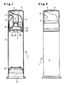
- FIGS. 1-3 showing a dispenser according to the invention.
- Figures 1 and 2 is in a vertical section (Fig. 1) and in a front view 2 shows a dispenser 1 for dispensing metered quantities of liquid to pasty products with a dispenser pump 10 designed according to the invention.
- the dispenser 1 consists of a storage container 3 with a lower open end 31 for filling the product to be dispensed. After filling, this open end 31 is then closed by a Nachschkolben 32.
- the upper end of the storage container 3 is bounded by a cover surface 30 with inlet valve 7.
- the dispenser head 2 On the storage container 3, the dispenser head 2 is pushed, consisting of the bell-shaped or dome-shaped dispenser pump 10 with an outlet 8 and with a discharge valve 8 downstream dispensing channel 6, mouthpiece 4 with application opening and locking tab 5.
- the dispenser head 2 is so on the storage container 3 postponed that the bottom open dispenser pump 10 is seated tightly on the top surface of the storage container 3 and is locked with this and between the dispenser pump 10 and the top surface 30, a pumping chamber 18 is formed.
- a cap 9 On the dispenser head 2, a cap 9 is pushed to protect it.
- valve flap 20 is formed for example by a rubber disc with a central hole 26, which is pushed onto a central mandrel 11 of the pump neck 12.
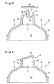
- the dispenser pump 10 of Figure 1 is shown enlarged again.
- the mandrel 11 has at the level of the upper edge 27 pump neck 12 a circumferential groove 14.
- the valve flap or here a rubber disc 20 is pushed with its central hole 26, wherein it engages in the groove 14 and sealingly rests on the upper edge 27 and thus the entire upper through hole 15 of the pump neck 12 is covered.
- FIG. 4 shows a different design of an outlet valve 8.
- the pump neck 12 is changed in this alternative embodiment.
- the upper end of the pump neck 12 is smooth and formed with a pivotable valve flap or cap 20 '.
- the pump neck 12 and the cap 20 ' were made in one piece and then partially separated by a separation process so that the cap 20' is only movably connected to the pump neck 12 via a small unseparated area, a tab 22.
- the thus movable cap 20 'or valve flap thus represents a particularly simple embodiment of a valve flap, the functionally reliable the pump neck 12 and the passage opening 15' sealingly closes and opens.
- FIGS. 5 and 6 a dispenser head 2 of a dispenser 1 with a dispenser pump 10 is shown in an enlarged partial section, the outlet valve 8 of which, according to FIG. 4, is not formed with a flat but with a dome-shaped valve flap 20 "which together with the Pump neck 12 was made.
- Fig. 5 the outlet valve 8 is shown with this - connected only via an unseparated tab 22 with the pump neck 12 - valve flap or cap 20 "in the open position and in Fig. 6 in the closed position.
- valve flap 33 of the inlet valve 7 is formed with a central hole elastic disc 33, preferably a rubber disc which is attached to a protruding mandrel 34 of the top surface 30, after which the projecting head of the mandrel 34 (via the disc 33) by a thermal Deformation was deformed at its end so that the disc 33 is now permanently attached to this mandrel 34
- annular groove 36 is formed from a container extending beyond the top surface 30 container extension 35 and the side edge 38 of the top surface 30, in which the lower edge of the side walls 13 are inserted and latched by a latching connection.
Landscapes
- Closures For Containers (AREA)
- Containers And Packaging Bodies Having A Special Means To Remove Contents (AREA)
- Jellies, Jams, And Syrups (AREA)
Description
- Die Erfindung betrifft einen Spender zur Abgabe dosierter Mengen flüssiger bis pastöser Produkte, bestehend aus einem unten offenen zylindrischen Speicherbehälter, dessen unteres offenes Ende durch einen axial verschiebbaren Kolben verschlossen ist und einem auf dem Speicherbehälter angeordneten Spenderkopf, der eine glockenförmige Spenderpumpe mit elastischen Seitenwänden enthält, die gemeinsam mit der Deckfläche des Speicherbehälters und deren Einlassventil und einem im Pumpenhals angeordneten Auslassventil eine geschlossene Pumpkammer ausbildet, wobei das Auslassventil als Teil des Pumpenhalses mit diesem so einstückig gefertigt ist, dass durch einen einfachen Arbeitsschritt die gesamte obere Durchgangsöffnung des Pumpenhalses mit einer Ventilklappe verschließbar ist, die in der Ausgangslage dichtend auf dem Pumpenhals aufliegt.
- Ein Spender der vorstehend beschriebenen Art ist aus der
EP 0 048 420 B1 bekannt. Der Spender besteht aus einem hohlzylindrischen Speicherbehälter mit einem unteren offenen Ende, welches durch einen axial verschiebbaren Nachrückkolben verschlossen ist. Das obere Ende des Speicherbehälters besitzt eine Deckfläche mit einem Einlassventil. Auf diesem zylindrischen Speicherbehälter ist ein Spenderkopf angeordnet mit einer im Spenderkopf befindlichen Spenderpumpe, deren Pumpkammer eingangs- und ausgangsseitig durch Rückschlagventile begrenzt ist sowie mit einem der Spenderpumpe nachgeordnetem Mundstück mit Applikationsöffnung ausgebildet ist. - Beim dosierten Austrag des zu spendenden Produktes wird durch einen nach unten gerichteten äußeren Druck auf die Spenderpumpe, wodurch sich diese zusammendrückt, das Auslassventil geöffnet und das Einlassventil geschlossen und das in der Pumpkammer befindliche Produkt über die Applikationsöffnung des Mundstücks heraus gedrückt.
- Beim Loslassen und dem darauffolgenden Entspannen und Ausdehnen der Spenderpumpe wird das Auslassventil geschlossen und das Eingangsventil geöffnet. Der sich durch das Ausdehnen der Spenderpumpe in der Pumpkammer ausbildende Unterdruck bewirkt nun ein Ansaugen von neuem Produkt aus dem Speicherbehälter durch das Einlassventil der Deckfläche, wobei gleichzeitig der Nachrückkolben bzw. Verschluss sich weiter in Richtung zur Deckfläche verschiebt. Dieser Vorgang kann solange wiederholt werden, bis der Speicherbehälter leer und der Nachrückkolben Kontakt mit der Deckfläche hat.
- Das Auslassventil ist als Klappenrückschlagventil ausgebildet und weist eine konkav ausgebildete, schwenkbar mit dem Ende des Pumpenhalses verbundene Ventilklappe auf, die in der Schließstellung domförmig auf dem vertikal angeordneten Pumpenhals aufliegt.
- Das in der Deckfläche des Behälters angeordnete Einlassventil besteht, wie vom gleichen Anmelder in der
US 4,394,939 zu diesem Spender näher ausgeführt wird, aus einem in der Deckfläche kreisförmig symmetrisch mit einem Winkel α (45° bis 85°) aus der radial zur Behälterachse verlaufenden Ebene herausgeneigten, mit Abstand zur Behälterachse verlaufenden Ringschlitz als Ventilöffnung, dessen Fläche die Form eines sich in Richtung auf den Pumpenraum erweiternden Pyramidenstumpfes bzw. Trichters aufweist. Als Ventilklappe dient hier ein mit Dichtlippen ausgebildeter kreisförmiger Abdeckring, der an mindestens drei, zu einer axial in Bezug auf den Behälter an der Deckfläche zu befestigenden Nabe führenden Speichen gehalten ist. Der Abdeckring, der der Schräglage des Ringschlitzes angepasst ist, liegt nur mit seinen Dichtlippen auf dem Ringschlitz dichtend an. - Aus der
DE 44 30 583 A1 ist ein Zahnpasta-Spender mit Pumpe bekannt, bestehend aus einem Pumpteil und einem Vorratsbehälter, die miteinander verschraubt sind. Das Pumpteil ist unten mit einer gegenüber dem Vorratsbehälter abschließenden, Ventilbohrungen enthaltenden Trennwand ausgebildet. Als Einlassventil des Pumpteils dient eine mit Abstand oberhalb der Ventilbohrungen auf der Trennwand mittig befestigte Ventilscheibe, die wechselweise entsprechend den durchgeführten Pumpzyklen die Ventilbohrungen öffnet und verschließt. Ein Auslassventil besitzt das Pumpteil nicht. - Gemeinsam bei derartigen Spendern ist, dass sie in der Regel nach ihrer Entleerung nicht mehr neu befüllt, sondern entsorgt werden. Dies hat zur Folge, dass deshalb auf eine möglichst preiswerte und einfache Herstellung des Wegwerfprodukts Spender" ein besonders großer Wert gelegt wird. Dies gilt insbesondere für die im Spender enthaltenen komplizierteren Konstruktionsteile wie beispielsweise für die Rückschlagventile, deren Ventilklappen mechanisch beansprucht und einwandfrei während der gesamten Lebensdauer des Spenders arbeiten sollen. Die Rückschlagventile befinden sich oftmals an schwer zugänglichen Stellen des Spenders, wodurch die Befestigung der meist angenieteten Ventilklappen oft nur schwierig und kostenintensiv durchgeführt werden kann.
- Ausgehend von diesem Stand der Technik ist es Aufgabe der Erfindung, bei Spendern der genannten Art die Ein- und Auslassventile möglichst einfach zu gestalten und montieren zu können.
- Die gestellte Aufgabe wird bei einem Spender der eingangs genannten Art mit den kennzeichnenden Merkmalen des Anspruchs 1 dadurch gelöst, dass die die Durchgangsöffnungen des Einlassventils und des Auslassventils verschließenden Ventilklappen gleichartig ausgebildet sind und jeweils aus einer flachen elastischen Scheibe mit zentralem Loch bestehen, die auf einem vorstehenden axialen Dorn der Deckfläche des Speicherbehälters bzw. auf einem vorstehenden axialen Dorn des Pumpenhalses aufgesteckt und dort befestigt sind, und die in der Ausgangslage in einer Ebene dichtend auf den Durchgangsöffnungen der Ventile flach aufliegen.
- Vorteilhafte Ausgestaltungen der Erfindung sind in den Unteransprüchen angegeben.
- Die als einstückiges Konstruktionselement glockenförmig ausgebildete Spenderpumpe des Spenderkopfes, die von unten in den Spenderkopf eingeschoben ist und die im montierten Zustand (auf dem Speicherbehälter ist der Spenderkopf aufgesteckt) gemeinsam mit der Deckfläche des Speicherbehälters eine Pumpkammer ausbildet, ist an ihrem oberen Ende zu einem Hals mit kreisrunden Querschnitt verengt. Dieser innen hohle Hals der Spenderpumpe stellt die Auslassöffnung der Pumpkammer dar und wird durch Anordnung einer Ventilklappe auf seinem oberen Ende als Auslassventil genutzt.
- Entsprechend einer vorteilhaften Ausgestaltung der Erfindung ist der vorstehende axiale Dorn des Pumpenhalses ein Teil der Spenderpumpe bzw. des Pumpenhalses und ist mit diesem einstückig gefertigt, wobei er über Stege mit dem Pumpenhals verbunden ist. Zur Befestigung der elastischen Scheibe, beispielsweise eine Gummischeibe, auf dem Dorn ist dieser mit einer umlaufenden Nut in Höhe der Oberkante des Pumpenhalses ausgebildet, in die die Gummischeibe beim Aufstecken einrastet.
- Zur Endmontage ist es also nur erforderlich, auf diesen Dorn der Spenderpumpe die Gummischeibe mit ihrer zentralen Bohrung aufzustecken, um die Auslassöffnung des Pumpenhalses zu einem Auslassventil umzubilden.
- Beim Spendevorgang, wobei das Auslassventil zum Austrag des Produkts geöffnet ist, ist die Gummischeibe mit ihrem äußeren Umfang nach oben in Richtung zum Mundstück verwölbt, während das Zentrum der Gummischeibe durch die umlaufende Nut des Dorns in seine ursprüngliche Position verbleibt. Bei der Rückstellung des Auslassventils durch den in der Pumpkammer erzeugten Unterdruck kehrt der äußere Rand in seine Ausgangslage zurück und die Gummischeibe liegt wieder dichtend auf dem Pumpenhals auf.
- Um die Herstellung des Auslassventils noch weiter zu vereinfachen, ist es auch möglich, einen Teil des Pumpenhalses als Ventilklappe zu verwenden.
- Hierzu wird der Pumpenhals mit eine den Hals oben abschließenden geschlossene Kappe einstückig gefertigt. Durch einen Trennvorgang wird diese Kappe dann vom Pumpenhals nur teilweise so abgetrennt, dass die Kappe über einen verbleibenden ungetrennten Bereich in Form einer Lasche mit dem Pumpenhals verbunden bleibt. Da die Lasche aus dem gleichen elastischen Material wie die gesamte Spenderpumpe gefertigt ist, wirkt die Lasche nun als ein Scharnier für die Ventilklappe, der ursprünglichen Kappe des Pumpenhalses.
- Die Fertigung dieser Ventilklappe reduziert sich somit auf einen einfachen teilweisen Trennvorgang an der einteilig durch beispielsweise Spritzguss gefertigten Spenderpumpe.
- Weitere Vorteile, Merkmale und Eigenschaften der Erfindung werden nachfolgend an in schematischen Zeichnungsfiguren dargestellten Ausführungsbeispielen näher erläutert, wobei nur Figuren 1-3 einen spender gemäß der Erfindung zeigen.
- Es zeigen:
- Fig. 1
- einen Spender gemäß der Erfindung in einem Vertikalschnitt,
- Fig. 2
- den Spender der Figur 1 in einer Vorderansicht,
- Fig. 3
- einen vergrößerten Teilausschnitt der Spenderpumpe in einem Vertikalschnitt,
- Fig. 4
- einen vergrößerten Teilausschnitt einer anderen Ausführung der Spenderpumpe in einem Vertikalschnitt,
- Fig. 5
- einen vergrößerten Teilausschnitt eines Spenders mit geöffnetem Auslassventil,
- Fig. 6
- einen vergrößerten Teilausschnitt eines Spenders mit geschlossenem Auslassventil gemäß Fig. 5.
- In den Figuren 1 und 2 ist in einem Vertikalschnitt (Fig. 1) und in einer Vorderansicht (Fig. 2) ein Spender 1 zur Abgabe dosierter Mengen flüssiger bis pastöser Produkte mit einer erfindungsmäßig ausgebildeten Spenderpumpe 10 dargestellt.
- Der Spender 1 besteht aus einem Speicherbehälter 3 mit einem unteren offenen Ende 31 zum Einfüllen des zu spendenden Produkts. Nach erfolgtem Einfüllen wird dieses offene Ende 31 dann durch einen Nachrückkolben 32 verschlossen. Das obere Ende des Speicherbehälters 3 ist durch eine Deckfläche 30 mit Einlassventil 7 begrenzt.
- Auf den Speicherbehälter 3 ist der Spenderkopf 2 aufgeschoben, bestehend aus der glockenförmigen bzw. domartigen Spenderpumpe 10 mit einem Auslassventil 8 und mit einem dem Auslassventil 8 nachgeordneten Spendekanal 6, Mundstück 4 mit Applikationsöffnung und Verschlusslasche 5. Der Spenderkopf 2 ist dabei so auf den Speicherbehälter 3 aufgeschoben, dass die unten offene Spenderpumpe 10 dicht auf der Deckfläche des Speicherbehälters 3 aufsitzt bzw. mit dieser verrastet ist und sich zwischen der Spenderpumpe 10 und der Deckfläche 30 eine Pumpkammer 18 ausbildet. Auf den Spenderkopf 2 ist zu dessen Schutz eine Kappe 9 aufgeschoben.
- Das Auslassventil 8 der glockenförmig ausgebildeten Spenderpumpe 10 befindet sich an ihrem offenen halsförmigen oberen Ende, auf dem eine Ventilklappe 20 dichtend aufliegt. Erfindungsgemäß wird diese Ventilklappe 20 beispielsweise durch eine Gummischeibe mit zentralem Loch 26 gebildet, die auf einem zentralen Dorn 11 des Pumpenhalses 12 aufgeschoben ist.
- In Figur 3 ist die Spenderpumpe 10 der Figur 1 nochmals vergrößert dargestellt. Im oberen Bereich des Pumpenhalses 12 sind in der hier vorhandenen Durchgangsöffnung 15 beispielsweise vier Stege 16 angeordnet, die einstückig mit dem gemeinsamen Dorn 11 ausgebildet sind. Der Dorn 11 besitzt in Höhe der Oberkante 27 Pumpenhalses 12 eine umlaufende Nut 14. Auf diesen Dorn 11 wird die Ventilklappe bzw. hier eine Gummischeibe 20 mit ihrem zentralen Loch 26 aufgeschoben, wobei sie in der Nut 14 einrastet und dichtend auf der Oberkante 27 aufliegt und damit die gesamte obere Durchgangsöffnung 15 des Pumpenhalses 12 bedeckt.
- Bei einem äußeren Druck in Pfeilrichtung 24 nach unten auf die Spenderpumpe 10, wodurch die elastischen Wände 13 der Spenderpumpe 10 nachgeben und sich der Pumpenhals 12 in gleicher Richtung nach unten bewegt, wird der Inhalt der Pumpkammer 18 in Pfeilrichtung 17 nach oben gedrückt, wodurch sich die Gummischeibe 20 an ihrem äußeren Umfang nach oben verwölbt und die Durchgangsöffnung 15 somit teilweise freigibt. Der mittlere Bereich der Gummischeibe 20 bleibt dabei in ihrer Lage unverändert, bedingt durch ihren Sitz in der Nut 14 des Dorns 11.
- In Figur 4 ist eine andersartige Ausbildung eines Auslassventils 8 dargestellt. Bei sonst gleicher Ausbildung der Spenderpumpe 10 ist bei dieser alternativen Ausführung lediglich der Pumpenhals 12 geändert. Unter Wegfall der Stege 16 und des Dorns 11 ist der obere Abschluss des Pumpenhalses 12 glatt und mit einer schwenkbaren Ventilklappe bzw. Kappe 20' ausgebildet. Der Pumpenhals 12 und die Kappe 20' wurden einstückig gefertigt und dann durch einen Trennvorgang soweit teilweise getrennt, dass die Kappe 20' nur noch über einen kleinen ungetrennten Bereich, einer Lasche 22 mit dem Pumpenhals 12 beweglich verbunden ist. Die so bewegliche Kappe 20' bzw. Ventilklappe stellt somit eine besonders einfache Ausführungsform einer Ventilklappe dar, die funktionssicher den Pumpenhals 12 bzw. die Durchgangsöffnung 15' dichtend verschließt und öffnet.
- In den Figuren 5 und 6 ist in einem vergrößerten Teilausschnitt ein Spenderkopf 2 eines Spenders 1 mit einer Spenderpumpe 10 dargestellt, deren Auslassventil 8 entsprechend der Fig. 4 nicht mit einer flachen sondern mit einer domartigen-Ventilklappe 20" ausgebildet ist, die gemeinsam mit dem Pumpenhals 12 gefertigt wurde.
- In Fig. 5 ist das Auslassventil 8 mit dieser - nur noch über eine ungetrennte Lasche 22 mit dem Pumpenhals 12 verbundene - Ventilklappe bzw. Kappe 20" in geöffneter Stellung und in der Fig. 6 in geschlossener Stellung abgebildet.
- Weiterhin ist aus dieser vergrößerten Darstellung des Spenderkopfes 2 die erfindungsgemäße nietförmige Verbindung der Ventilklappe 33 des Einlassventils 7 mit der Deckfläche 30 des Speicherbehälters 3 deutlicher als bei der Figur 1 zu ersehen. Hierbei ist die Ventilklappe 33 des Einlassventils 7 eine mit einem zentralen Loch ausgebildete elastische Scheibe 33, vorzugsweise eine Gummischeibe, die auf einen vorstehenden Dorn 34 der Deckfläche 30 aufgesteckt ist, wonach der überstehende Kopf des Dorns 34 (über die Scheibe 33) durch eine thermische Verformung an seinem Ende derart deformiert wurde, dass die Scheibe 33 nun unlösbar auf diesem Dorn 34 befestigt
- Gleichfalls deutlicher ist den Figuren 5 und 6 die Befestigung der Spenderpumpe 10 mit ihren Seitenwänden 13 mittels einer Rastverbindung 37 in einer ringförmigen Nut 36 des Speicherbehälters 3 zu entnehmen. Die ringförmige Nut 36 ist aus einer über die Deckfläche 30 hinausreichenden Behälterverlängerung 35 und dem Seitenrand 38 der Deckfläche 30 gebildet, in die der untere Rand der Seitenwände 13 eingeschoben und mittels einer Rastverbindung verrastet sind.
- Ein Spender in der Ausbildung der Figuren 5 und 6 ist auf Grund der wenigen und einfach gestalteten Konstruktionsteile des Spenderkopfes in einfacher Weise beispielhaft mit folgenden Arbeitsschritten montierbar:
- a) auf den ohne Spenderpumpe 10 von oben zugänglichen Dorn (Nietkopf) 34 wird als Ventilklappe 33 die elastische Scheibe aufgeschoben und danach der Dorn 34 verformt;
- b) die Kappe 20" des Pumpenhalses 12 wird teilweise vom Pumpenhals 12 abgetrennt;
- c)die nach b) vorbereitete Spenderpumpe 10 wird in die Nut 36 des Speicherbehälters 3 eingeschoben und dort verrastet ;
- d) der Spendekanal 6 des Spenderkopfes 2 wird auf den Pumpenhals 12 aufgeschoben und dort mittels einer Rastverbindung 39 befestigt.
-
- 1
- Spender
- 2
- Spenderkopf
- 3
- Speicherbehälter
- 4
- Mundstück
- 5
- Verschlusslasche
- 6
- Spendekanal
- 7
- Einlassventil
- 8
- Auslassventil
- 9
- Kappe
- 10
- glockenförmige Spenderpumpe (Dom)
- 11
- Dorn
- 12
- Pumpenhals
- 13
- elastische Seitenwände des Dorns
- 14
- Nut im Dorn
- 15, 15', 15"
- Durchgangsöffnung
- 16
- Stege
- 17
- Ausstömrichtung
- 18
- Pumpkammer
- 20, 20', 20"
- obere Ventilklappe
- 22
- Lasche
- 24
- Druckrichtung
- 26
- Loch in Gummischeibe
- 27
- Oberkante Pumpenhals
- 30
- Deckfläche
- 31
- offenes Ende des Speicherbehälters 3
- 32
- Kolben
- 33
- untere Ventilklappe (Gummi)
- 34
- Nietkopf
- 35
- Behälterverlängerung
- 36
- ringförmige Nut
- 37
- Rastverbindung
- 38
- Seitenrand der Deckfläche
- 39
- Rastverbindung
Claims (5)
- Spender (1) zur Abgabe dosierter Mengen flüssiger bis pastöser Produkte, bestehend aus einem unten offenen zylindrischen Speicherbehälter (3), dessen unteres offenes Ende (31) durch einen axial verschiebbaren Kolben (32) verschlossen ist, und einem auf dem Speicherbehälter (3) angeordneten Spenderkopf (2), der eine glockenförmige Spenderpumpe (10) mit elastischen Seitenwänden (13) enthält, die gemeinsam mit der Deckfläche (30) des Speicherbehälters (3) und deren Einlassventil (7) und einem im Pumpenhals (12) angeordneten Auslassventil (8) eine geschlossene Pumpkammer (18) ausbildet, wobei das Auslassventil (8) als Teil des Pumpenhalses (12) mit diesem so einstückig gefertigt ist, dass durch einen einfachen Arbeitsschritt die gesamte obere Durchgangsöffnung des Pumpenhalses (12) mit einer Ventilklappe (20) verschließbar ist, die in der Ausgangslage dichtend auf dem Pumpenhals (12) aufliegt, dadurch gekennzeichnet, dass die die Durchgangsöffnungen des Einlassventils (7) und des Auslassventils (8) verschließenden Ventilklappen (20, 33) gleichartig ausgebildet sind und jeweils aus einer flachen elastischen Scheibe mit zentralem Loch bestehen, die auf einem vorstehenden axialen Dorn (34) der Deckfläche (30) des Speicherbehälters (3) bzw. auf einem vorstehenden axialen Dorn (11) des Pumpenhalses (12) aufgesteckt und dort befestigt sind, und die in der Ausgangslage in einer Ebene dichtend auf den Durchgangsöffnungen der Ventile (7, 8) flach aufliegen.
- Spender (1) nach Anspruch 1, dadurch gekennzeichnet, dass die Ventilklappen (20, 33) flach aufliegende Gummischeiben sind.
- Spender (1) nach Anspruch 1 oder 2, dadurch gekennzeichnet, dass der Dorn (11) ein Teil des Pumpenhalses (12) ist und mit diesem einstückig gefertigt und über Stege (16) verbunden ist.
- Spender (1) nach Anspruch 3, dadurch gekennzeichnet, dass der Dorn (11) mit einer umlaufenden Nut (14) in Höhe der Oberkante (27) des Pumpenhalses (12) zum Einrasten der Ventilklappe (20) auf dem Dorn (11) ausgebildet ist.
- Spender (1) nach Anspruch 1, 2, 3 oder 4, dadurch gekennzeichnet, dass die elastische Ventilklappe (33) nach ihrem Aufstecken auf den Dorn (34) durch eine nietförmige thermische Verformung des Dorns (34) unlösbar auf diesem befestigt ist.
Applications Claiming Priority (2)
| Application Number | Priority Date | Filing Date | Title |
|---|---|---|---|
| DE20201742U DE20201742U1 (de) | 2002-02-05 | 2002-02-05 | Spender für fließfähige Produkte |
| DE20201742U | 2002-02-05 |
Publications (3)
| Publication Number | Publication Date |
|---|---|
| EP1332798A2 EP1332798A2 (de) | 2003-08-06 |
| EP1332798A3 EP1332798A3 (de) | 2003-08-20 |
| EP1332798B1 true EP1332798B1 (de) | 2007-09-19 |
Family
ID=7967399
Family Applications (1)
| Application Number | Title | Priority Date | Filing Date |
|---|---|---|---|
| EP03002285A Expired - Lifetime EP1332798B1 (de) | 2002-02-05 | 2003-02-03 | Spender für flüssige oder pastöse Produkte |
Country Status (4)
| Country | Link |
|---|---|
| US (1) | US7028865B2 (de) |
| EP (1) | EP1332798B1 (de) |
| AT (1) | ATE373521T1 (de) |
| DE (2) | DE20201742U1 (de) |
Families Citing this family (20)
| Publication number | Priority date | Publication date | Assignee | Title |
|---|---|---|---|---|
| US7654418B2 (en) * | 2004-08-30 | 2010-02-02 | Rieke Corporation | Airless dispensing pump |
| US7367476B2 (en) | 2004-08-30 | 2008-05-06 | Rieke Corporation | Airless dispensing pump with tamper evidence features |
| FR2900643B1 (fr) * | 2006-05-05 | 2008-10-10 | Airlessystems Soc Par Actions | Organe de distribution de produit fluide et distributeur comprenant un tel organe de distribution |
| DE602006004849D1 (de) * | 2006-05-15 | 2009-03-05 | Wintek Sarl | Spender für fliessfähige Produkte mit einer Druckkolbenpumpe und einer Membrane |
| KR100856326B1 (ko) * | 2006-07-19 | 2008-09-03 | 삼성전기주식회사 | 레이저 리프트 오프를 이용한 유전체 박막을 갖는 박막 커패시터 내장된 인쇄회로기판 제조방법, 및 이로부터 제조된 박막 커패시터 내장된 인쇄회로기판 |
| DE102008029004A1 (de) * | 2007-06-29 | 2009-01-02 | Rpc Bramlage Gmbh | Spender zur Ausgabe flüssiger oder pastöser Massen |
| IT1399593B1 (it) * | 2010-04-14 | 2013-04-26 | Guala Dispensing Spa | Erogatore a grilletto per liquidi con valvola di aspirazione. |
| IT1399592B1 (it) * | 2010-04-14 | 2013-04-26 | Guala Dispensing Spa | Erogatore a grilletto per liquidi con fermo per la valvola di mandata. |
| WO2013023129A1 (en) * | 2011-08-11 | 2013-02-14 | Soneco Llc | Securing product storage tanks against unauthorized delivery |
| EP3131429B1 (de) * | 2014-05-07 | 2020-01-01 | Colgate-Palmolive Company | Mundpflegehilfsmittel und verfahren zur herstellung davon |
| KR101501027B1 (ko) * | 2014-06-16 | 2015-03-12 | (주)연우 | 캡슐 토출용 펌프 용기 |
| FR3041409A1 (fr) * | 2015-09-22 | 2017-03-24 | Cep Tubes | Valve anti-retour etanche |
| GB201518910D0 (en) * | 2015-10-26 | 2015-12-09 | Rieke Packaging Systems Ltd | Dispensers |
| FR3048192B1 (fr) * | 2016-02-25 | 2020-10-23 | Albea Lacrost | Pompe pour receptacle, notamment un flacon de produit cosmetique, et dispositif de distribution comprenant une telle pompe |
| EP3484628B1 (de) * | 2016-07-18 | 2020-08-26 | RPC Bramlage GmbH | Spender für flüssige bis pastöse massen |
| WO2019121399A1 (en) * | 2017-12-20 | 2019-06-27 | Sulzer Mixpac Ag | Piston, cartridge and method of venting a cartridge |
| US12070768B2 (en) | 2017-12-20 | 2024-08-27 | Medmix Switzerland Ag | Piston, cartridge and method of venting a cartridge |
| CN111731667A (zh) * | 2020-07-07 | 2020-10-02 | 上海升村包装材料有限公司 | 一种环保型喷泵 |
| FR3098797B1 (fr) * | 2019-07-19 | 2022-01-28 | Promens Sa | Dispositif de bouchage d’un contenant d’un produit liquide à pâteux et recharge fermée par un tel dispositif |
| EP4003605B1 (de) * | 2019-07-23 | 2024-04-10 | Rieke Packaging Systems Limited | Voll-polymer-pumpenspender mit innenstopfendichtung |
Family Cites Families (19)
| Publication number | Priority date | Publication date | Assignee | Title |
|---|---|---|---|---|
| AT61990B (de) | 1911-12-11 | 1913-11-10 | Emil Merten | Mitnehmerklinken-Schaltwerk für Kettenrädergetriebe. |
| DE2611644A1 (de) * | 1976-03-19 | 1977-09-29 | Henkel & Cie Gmbh | Behaelter fuer kosmetika |
| DE3035705A1 (de) * | 1980-09-22 | 1982-05-06 | Henkel KGaA, 4000 Düsseldorf | Spender |
| DE3035728A1 (de) | 1980-09-22 | 1982-05-06 | Henkel KGaA, 4000 Düsseldorf | Spender |
| DE3035742A1 (de) | 1980-09-22 | 1982-05-13 | Henkel KGaA, 4000 Düsseldorf | Klappenventil |
| EP0084638B1 (de) * | 1982-01-19 | 1987-12-23 | Gap Gesellschaft Für Auswertungen Und Patente Ag | Spender für pastöse Produkte |
| US4535820A (en) | 1984-05-24 | 1985-08-20 | Burron Medical Inc. | Normally closed check valve |
| DE3725650A1 (de) | 1987-08-03 | 1989-02-23 | Fehrer Gummihaar | Herstellung einer verbindung zwischen einem aus geschaeumtem kunststoff bestehenden teil und einem anbauelement |
| FR2621014B1 (fr) * | 1987-09-25 | 1989-11-24 | Cebal | Distributeur de produit pateux a fonctionnement ameliore et element de pompage correspondant |
| DE3738548A1 (de) * | 1987-11-13 | 1989-05-24 | Bramlage Gmbh | Spender fuer pastoese massen |
| US4936493A (en) * | 1987-11-23 | 1990-06-26 | Calmar, Inc. | Elastomeric valve and piston structure for product dispenser |
| DE4307752A1 (de) * | 1993-03-11 | 1994-09-15 | Coster Tecnologie Speciali Spa | Vorrichtung zum dosierten Austrag eines fließfähigen Mediums aus einem Behälter |
| DE4430583A1 (de) | 1994-08-18 | 1996-02-22 | Harald Dipl Ing Loesche | Zahnpasta-Spender mit Pumpe |
| US5544789A (en) | 1995-01-05 | 1996-08-13 | Calmar Inc. | Bellows pump dispenser |
| FR2731690B1 (fr) | 1995-03-17 | 1997-06-06 | Total Raffinage Distribution | Dispositif de limitation de perte de liquide, adaptable sur un organe de distribution de liquide sous pression |
| JP3527324B2 (ja) | 1995-07-13 | 2004-05-17 | 株式会社吉野工業所 | クリーム状物注出容器 |
| DE29712144U1 (de) * | 1997-07-10 | 1997-09-25 | Wiegner, Georg, Kowloon, Hong Kong | Pumpe zum dosierten Austragen von flüssigen, gelartigen oder viskosen Substanzen |
| DE19729516C2 (de) * | 1997-07-10 | 1999-04-22 | Georg Wiegner | Pumpe zum dosierten Austragen von flüssigen, gelartigen oder viskosen Substanzen |
| JP2000117162A (ja) | 1998-10-14 | 2000-04-25 | Akira Matsumoto | 簡易型ポンプディスペンサー |
-
2002
- 2002-02-05 DE DE20201742U patent/DE20201742U1/de not_active Expired - Lifetime
-
2003
- 2003-01-29 US US10/353,822 patent/US7028865B2/en not_active Expired - Fee Related
- 2003-02-03 AT AT03002285T patent/ATE373521T1/de not_active IP Right Cessation
- 2003-02-03 EP EP03002285A patent/EP1332798B1/de not_active Expired - Lifetime
- 2003-02-03 DE DE50308202T patent/DE50308202D1/de not_active Expired - Lifetime
Non-Patent Citations (1)
| Title |
|---|
| None * |
Also Published As
| Publication number | Publication date |
|---|---|
| EP1332798A2 (de) | 2003-08-06 |
| DE20201742U1 (de) | 2003-03-20 |
| US20030168475A1 (en) | 2003-09-11 |
| ATE373521T1 (de) | 2007-10-15 |
| US7028865B2 (en) | 2006-04-18 |
| DE50308202D1 (de) | 2007-10-31 |
| EP1332798A3 (de) | 2003-08-20 |
Similar Documents
| Publication | Publication Date | Title |
|---|---|---|
| EP0112351B1 (de) | Spender für pastöse produkte | |
| EP0230252B2 (de) | Spender für pastöse Produkte | |
| EP0738543B1 (de) | Abgabepumpe aus Kunststoff für pastenartige Stoffe | |
| EP1332798A2 (de) | Spender für flüssige oder pastöse Produkte | |
| DE19729516C2 (de) | Pumpe zum dosierten Austragen von flüssigen, gelartigen oder viskosen Substanzen | |
| DE69522549T2 (de) | Vorrichtung zur abgabe von steriler flüssigkeit | |
| EP0013691B1 (de) | Spender für pastöse Produkte | |
| EP0312722B1 (de) | Dosier- und Spraypumpe für flüssige oder viskose Stoffe | |
| DE69323502T2 (de) | WEGWERFFLüSSIGKEITSPUMPE AUS KUNSTSTOFF | |
| EP2018227B1 (de) | Abgabevorrichtung | |
| DE20006099U1 (de) | Dosierpumpenspender mit wenigstens zwei Dosierpumpen | |
| EP3484628B1 (de) | Spender für flüssige bis pastöse massen | |
| WO1986001489A1 (fr) | Recipient muni d'un obturateur | |
| DE602004005607T2 (de) | Fluidproduktabgabekopf | |
| EP2016003B1 (de) | Selbstschliessendes ventil mit ventildeckel | |
| EP2869934B1 (de) | Abgabekopf und abgabevorrichtung | |
| EP0250965A1 (de) | Spender | |
| DE10351565B4 (de) | Selbstschließender Fluidspendeverschluss | |
| DE2640837A1 (de) | Manuell betaetigbare pumpe | |
| EP3736049B1 (de) | Austragkopf und flüssigkeitsspender mit einem austragkopf | |
| EP0345458A2 (de) | Spender | |
| EP3694654A1 (de) | Spender zur ausgabe flüssiger oder pastöser massen | |
| WO2007122087A1 (de) | Spender zur ausgabe flüssiger bis pastöser massen | |
| EP1344570B1 (de) | Spender zur Applikation fliessfähiger Produkte | |
| DE69812621T2 (de) | In Öffnungs- sowie Schliessstellung abgedichter, handbetätigter Spender |
Legal Events
| Date | Code | Title | Description |
|---|---|---|---|
| PUAI | Public reference made under article 153(3) epc to a published international application that has entered the european phase |
Free format text: ORIGINAL CODE: 0009012 |
|
| PUAL | Search report despatched |
Free format text: ORIGINAL CODE: 0009013 |
|
| AK | Designated contracting states |
Designated state(s): AT BE BG CH CY CZ DE DK EE ES FI FR GB GR HU IE IT LI LU MC NL PT SE SI SK TR |
|
| AX | Request for extension of the european patent |
Extension state: AL LT LV MK RO |
|
| AK | Designated contracting states |
Designated state(s): AT BE BG CH CY CZ DE DK EE ES FI FR GB GR HU IE IT LI LU MC NL PT SE SI SK TR |
|
| AX | Request for extension of the european patent |
Extension state: AL LT LV MK RO |
|
| 17P | Request for examination filed |
Effective date: 20031209 |
|
| AKX | Designation fees paid |
Designated state(s): AT BE BG CH CY CZ DE DK EE ES FI FR GB GR HU IE IT LI LU MC NL PT SE SI SK TR |
|
| 17Q | First examination report despatched |
Effective date: 20041215 |
|
| 17Q | First examination report despatched |
Effective date: 20041215 |
|
| GRAP | Despatch of communication of intention to grant a patent |
Free format text: ORIGINAL CODE: EPIDOSNIGR1 |
|
| GRAS | Grant fee paid |
Free format text: ORIGINAL CODE: EPIDOSNIGR3 |
|
| GRAA | (expected) grant |
Free format text: ORIGINAL CODE: 0009210 |
|
| AK | Designated contracting states |
Kind code of ref document: B1 Designated state(s): AT BE BG CH CY CZ DE DK EE ES FI FR GB GR HU IE IT LI LU MC NL PT SE SI SK TR |
|
| REG | Reference to a national code |
Ref country code: GB Ref legal event code: FG4D Free format text: NOT ENGLISH |
|
| GBT | Gb: translation of ep patent filed (gb section 77(6)(a)/1977) |
Effective date: 20070919 |
|
| REG | Reference to a national code |
Ref country code: CH Ref legal event code: EP |
|
| REF | Corresponds to: |
Ref document number: 50308202 Country of ref document: DE Date of ref document: 20071031 Kind code of ref document: P |
|
| REG | Reference to a national code |
Ref country code: IE Ref legal event code: FG4D Free format text: LANGUAGE OF EP DOCUMENT: GERMAN |
|
| PG25 | Lapsed in a contracting state [announced via postgrant information from national office to epo] |
Ref country code: FI Free format text: LAPSE BECAUSE OF FAILURE TO SUBMIT A TRANSLATION OF THE DESCRIPTION OR TO PAY THE FEE WITHIN THE PRESCRIBED TIME-LIMIT Effective date: 20070919 |
|
| NLV1 | Nl: lapsed or annulled due to failure to fulfill the requirements of art. 29p and 29m of the patents act | ||
| RAP2 | Party data changed (patent owner data changed or rights of a patent transferred) |
Owner name: RPC WIKO GMBH |
|
| PG25 | Lapsed in a contracting state [announced via postgrant information from national office to epo] |
Ref country code: ES Free format text: LAPSE BECAUSE OF FAILURE TO SUBMIT A TRANSLATION OF THE DESCRIPTION OR TO PAY THE FEE WITHIN THE PRESCRIBED TIME-LIMIT Effective date: 20071230 Ref country code: GR Free format text: LAPSE BECAUSE OF FAILURE TO SUBMIT A TRANSLATION OF THE DESCRIPTION OR TO PAY THE FEE WITHIN THE PRESCRIBED TIME-LIMIT Effective date: 20071220 Ref country code: NL Free format text: LAPSE BECAUSE OF FAILURE TO SUBMIT A TRANSLATION OF THE DESCRIPTION OR TO PAY THE FEE WITHIN THE PRESCRIBED TIME-LIMIT Effective date: 20070919 |
|
| REG | Reference to a national code |
Ref country code: IE Ref legal event code: FD4D |
|
| ET | Fr: translation filed | ||
| PG25 | Lapsed in a contracting state [announced via postgrant information from national office to epo] |
Ref country code: SK Free format text: LAPSE BECAUSE OF FAILURE TO SUBMIT A TRANSLATION OF THE DESCRIPTION OR TO PAY THE FEE WITHIN THE PRESCRIBED TIME-LIMIT Effective date: 20070919 Ref country code: PT Free format text: LAPSE BECAUSE OF FAILURE TO SUBMIT A TRANSLATION OF THE DESCRIPTION OR TO PAY THE FEE WITHIN THE PRESCRIBED TIME-LIMIT Effective date: 20080219 Ref country code: CZ Free format text: LAPSE BECAUSE OF FAILURE TO SUBMIT A TRANSLATION OF THE DESCRIPTION OR TO PAY THE FEE WITHIN THE PRESCRIBED TIME-LIMIT Effective date: 20070919 |
|
| PG25 | Lapsed in a contracting state [announced via postgrant information from national office to epo] |
Ref country code: SE Free format text: LAPSE BECAUSE OF FAILURE TO SUBMIT A TRANSLATION OF THE DESCRIPTION OR TO PAY THE FEE WITHIN THE PRESCRIBED TIME-LIMIT Effective date: 20071219 |
|
| PLBE | No opposition filed within time limit |
Free format text: ORIGINAL CODE: 0009261 |
|
| STAA | Information on the status of an ep patent application or granted ep patent |
Free format text: STATUS: NO OPPOSITION FILED WITHIN TIME LIMIT |
|
| PG25 | Lapsed in a contracting state [announced via postgrant information from national office to epo] |
Ref country code: DK Free format text: LAPSE BECAUSE OF FAILURE TO SUBMIT A TRANSLATION OF THE DESCRIPTION OR TO PAY THE FEE WITHIN THE PRESCRIBED TIME-LIMIT Effective date: 20070919 |
|
| 26N | No opposition filed |
Effective date: 20080620 |
|
| BERE | Be: lapsed |
Owner name: RPC WIKO G.M.B.H. & CO. KG Effective date: 20080228 |
|
| REG | Reference to a national code |
Ref country code: CH Ref legal event code: PL |
|
| PG25 | Lapsed in a contracting state [announced via postgrant information from national office to epo] |
Ref country code: CH Free format text: LAPSE BECAUSE OF NON-PAYMENT OF DUE FEES Effective date: 20080229 Ref country code: LI Free format text: LAPSE BECAUSE OF NON-PAYMENT OF DUE FEES Effective date: 20080229 Ref country code: IE Free format text: LAPSE BECAUSE OF FAILURE TO SUBMIT A TRANSLATION OF THE DESCRIPTION OR TO PAY THE FEE WITHIN THE PRESCRIBED TIME-LIMIT Effective date: 20070919 Ref country code: MC Free format text: LAPSE BECAUSE OF NON-PAYMENT OF DUE FEES Effective date: 20080228 |
|
| PG25 | Lapsed in a contracting state [announced via postgrant information from national office to epo] |
Ref country code: EE Free format text: LAPSE BECAUSE OF FAILURE TO SUBMIT A TRANSLATION OF THE DESCRIPTION OR TO PAY THE FEE WITHIN THE PRESCRIBED TIME-LIMIT Effective date: 20070919 |
|
| PG25 | Lapsed in a contracting state [announced via postgrant information from national office to epo] |
Ref country code: BE Free format text: LAPSE BECAUSE OF NON-PAYMENT OF DUE FEES Effective date: 20080228 |
|
| PG25 | Lapsed in a contracting state [announced via postgrant information from national office to epo] |
Ref country code: AT Free format text: LAPSE BECAUSE OF NON-PAYMENT OF DUE FEES Effective date: 20080203 |
|
| PG25 | Lapsed in a contracting state [announced via postgrant information from national office to epo] |
Ref country code: SI Free format text: LAPSE BECAUSE OF FAILURE TO SUBMIT A TRANSLATION OF THE DESCRIPTION OR TO PAY THE FEE WITHIN THE PRESCRIBED TIME-LIMIT Effective date: 20070919 |
|
| PG25 | Lapsed in a contracting state [announced via postgrant information from national office to epo] |
Ref country code: CY Free format text: LAPSE BECAUSE OF FAILURE TO SUBMIT A TRANSLATION OF THE DESCRIPTION OR TO PAY THE FEE WITHIN THE PRESCRIBED TIME-LIMIT Effective date: 20070919 |
|
| PG25 | Lapsed in a contracting state [announced via postgrant information from national office to epo] |
Ref country code: BG Free format text: LAPSE BECAUSE OF FAILURE TO SUBMIT A TRANSLATION OF THE DESCRIPTION OR TO PAY THE FEE WITHIN THE PRESCRIBED TIME-LIMIT Effective date: 20071219 |
|
| PGFP | Annual fee paid to national office [announced via postgrant information from national office to epo] |
Ref country code: FR Payment date: 20100315 Year of fee payment: 8 |
|
| PGFP | Annual fee paid to national office [announced via postgrant information from national office to epo] |
Ref country code: DE Payment date: 20100108 Year of fee payment: 8 Ref country code: GB Payment date: 20100219 Year of fee payment: 8 |
|
| PG25 | Lapsed in a contracting state [announced via postgrant information from national office to epo] |
Ref country code: LU Free format text: LAPSE BECAUSE OF NON-PAYMENT OF DUE FEES Effective date: 20080203 Ref country code: HU Free format text: LAPSE BECAUSE OF FAILURE TO SUBMIT A TRANSLATION OF THE DESCRIPTION OR TO PAY THE FEE WITHIN THE PRESCRIBED TIME-LIMIT Effective date: 20080320 |
|
| PG25 | Lapsed in a contracting state [announced via postgrant information from national office to epo] |
Ref country code: TR Free format text: LAPSE BECAUSE OF FAILURE TO SUBMIT A TRANSLATION OF THE DESCRIPTION OR TO PAY THE FEE WITHIN THE PRESCRIBED TIME-LIMIT Effective date: 20070919 |
|
| PG25 | Lapsed in a contracting state [announced via postgrant information from national office to epo] |
Ref country code: IT Free format text: LAPSE BECAUSE OF NON-PAYMENT OF DUE FEES Effective date: 20080229 |
|
| GBPC | Gb: european patent ceased through non-payment of renewal fee |
Effective date: 20110203 |
|
| REG | Reference to a national code |
Ref country code: FR Ref legal event code: ST Effective date: 20111102 |
|
| REG | Reference to a national code |
Ref country code: DE Ref legal event code: R119 Ref document number: 50308202 Country of ref document: DE Effective date: 20110901 |
|
| PG25 | Lapsed in a contracting state [announced via postgrant information from national office to epo] |
Ref country code: FR Free format text: LAPSE BECAUSE OF NON-PAYMENT OF DUE FEES Effective date: 20110228 |
|
| PG25 | Lapsed in a contracting state [announced via postgrant information from national office to epo] |
Ref country code: GB Free format text: LAPSE BECAUSE OF NON-PAYMENT OF DUE FEES Effective date: 20110203 |
|
| PG25 | Lapsed in a contracting state [announced via postgrant information from national office to epo] |
Ref country code: DE Free format text: LAPSE BECAUSE OF NON-PAYMENT OF DUE FEES Effective date: 20110901 |