EP1331748A2 - Verfahren zur Sicherung eines optischen Ring-Übertragungsnetzwerks und verstärkender Kommunikationsknoten und Verkehrskonzentrator - Google Patents
Verfahren zur Sicherung eines optischen Ring-Übertragungsnetzwerks und verstärkender Kommunikationsknoten und Verkehrskonzentrator Download PDFInfo
- Publication number
- EP1331748A2 EP1331748A2 EP03290188A EP03290188A EP1331748A2 EP 1331748 A2 EP1331748 A2 EP 1331748A2 EP 03290188 A EP03290188 A EP 03290188A EP 03290188 A EP03290188 A EP 03290188A EP 1331748 A2 EP1331748 A2 EP 1331748A2
- Authority
- EP
- European Patent Office
- Prior art keywords
- network
- optical
- fiber
- signals
- transmission state
- Prior art date
- Legal status (The legal status is an assumption and is not a legal conclusion. Google has not performed a legal analysis and makes no representation as to the accuracy of the status listed.)
- Withdrawn
Links
Images


Classifications
-
- H—ELECTRICITY
- H04—ELECTRIC COMMUNICATION TECHNIQUE
- H04Q—SELECTING
- H04Q11/00—Selecting arrangements for multiplex systems
- H04Q11/0001—Selecting arrangements for multiplex systems using optical switching
- H04Q11/0062—Network aspects
-
- H—ELECTRICITY
- H04—ELECTRIC COMMUNICATION TECHNIQUE
- H04B—TRANSMISSION
- H04B10/00—Transmission systems employing electromagnetic waves other than radio-waves, e.g. infrared, visible or ultraviolet light, or employing corpuscular radiation, e.g. quantum communication
- H04B10/07—Arrangements for monitoring or testing transmission systems; Arrangements for fault measurement of transmission systems
- H04B10/075—Arrangements for monitoring or testing transmission systems; Arrangements for fault measurement of transmission systems using an in-service signal
- H04B10/079—Arrangements for monitoring or testing transmission systems; Arrangements for fault measurement of transmission systems using an in-service signal using measurements of the data signal
- H04B10/0791—Fault location on the transmission path
-
- H—ELECTRICITY
- H04—ELECTRIC COMMUNICATION TECHNIQUE
- H04B—TRANSMISSION
- H04B10/00—Transmission systems employing electromagnetic waves other than radio-waves, e.g. infrared, visible or ultraviolet light, or employing corpuscular radiation, e.g. quantum communication
- H04B10/07—Arrangements for monitoring or testing transmission systems; Arrangements for fault measurement of transmission systems
- H04B10/075—Arrangements for monitoring or testing transmission systems; Arrangements for fault measurement of transmission systems using an in-service signal
- H04B10/079—Arrangements for monitoring or testing transmission systems; Arrangements for fault measurement of transmission systems using an in-service signal using measurements of the data signal
- H04B10/0793—Network aspects, e.g. central monitoring of transmission parameters
-
- H—ELECTRICITY
- H04—ELECTRIC COMMUNICATION TECHNIQUE
- H04B—TRANSMISSION
- H04B10/00—Transmission systems employing electromagnetic waves other than radio-waves, e.g. infrared, visible or ultraviolet light, or employing corpuscular radiation, e.g. quantum communication
- H04B10/27—Arrangements for networking
- H04B10/275—Ring-type networks
- H04B10/2755—Ring-type networks with a headend
-
- H—ELECTRICITY
- H04—ELECTRIC COMMUNICATION TECHNIQUE
- H04J—MULTIPLEX COMMUNICATION
- H04J14/00—Optical multiplex systems
- H04J14/02—Wavelength-division multiplex systems
- H04J14/0278—WDM optical network architectures
- H04J14/0283—WDM ring architectures
-
- H—ELECTRICITY
- H04—ELECTRIC COMMUNICATION TECHNIQUE
- H04J—MULTIPLEX COMMUNICATION
- H04J14/00—Optical multiplex systems
- H04J14/02—Wavelength-division multiplex systems
- H04J14/0287—Protection in WDM systems
- H04J14/0289—Optical multiplex section protection
-
- H—ELECTRICITY
- H04—ELECTRIC COMMUNICATION TECHNIQUE
- H04J—MULTIPLEX COMMUNICATION
- H04J14/00—Optical multiplex systems
- H04J14/02—Wavelength-division multiplex systems
- H04J14/0287—Protection in WDM systems
- H04J14/0293—Optical channel protection
-
- H—ELECTRICITY
- H04—ELECTRIC COMMUNICATION TECHNIQUE
- H04Q—SELECTING
- H04Q11/00—Selecting arrangements for multiplex systems
- H04Q11/0001—Selecting arrangements for multiplex systems using optical switching
- H04Q11/0062—Network aspects
- H04Q2011/0079—Operation or maintenance aspects
- H04Q2011/0081—Fault tolerance; Redundancy; Recovery; Reconfigurability
-
- H—ELECTRICITY
- H04—ELECTRIC COMMUNICATION TECHNIQUE
- H04Q—SELECTING
- H04Q11/00—Selecting arrangements for multiplex systems
- H04Q11/0001—Selecting arrangements for multiplex systems using optical switching
- H04Q11/0062—Network aspects
- H04Q2011/009—Topology aspects
- H04Q2011/0092—Ring
Definitions
- the present invention relates to the field of optical telecommunications and more particularly describes a method and devices ensuring the security of an optical telecommunications network in a ring.
- the networks in the prior art ring comprise an additional fiber of security as well as an additional communication node of securing by operating communication node, the security being substantially identical to the latter, linked to the same network local and associated with the security fiber.
- the traffic concentrator duplicates the signals descendants. Some of these so-called operating signals are transported by a first optical fiber to the upstream of the operation in a given direction of propagation. Another part of these signals, known as security signals, are transported by the security fiber upstream of the security node in the opposite direction to the signals operation. Then, referral means coupled with the first fiber and the securing fiber activate one of the nodes depending on the state of network transmission, allowing signals to pass through descendants of operation or security in the OADM corresponding.
- amplified communication nodes are also inserted in the securing fiber.
- the object of the present invention is to develop a method and devices ensuring low-cost security of traffic in a network ring optical telecommunications.
- the present invention first proposes a method for securing an optical ring telecommunications network, the network including a traffic concentrator and a communication node interconnected via an optical fiber of the network, the concentrator transmitting signals.
- optics transported in the fiber and intended for the node characterized in that it consists in using the same fiber in one direction when the network is in a normal transmission state, and in the opposite direction when the network is in a backup transmission state.
- This method thus secures the transmission of downlink optical signals emitted by the concentrator because, in the event of a break of the ring, each node of the network will receive the downlink signals, which are intended for it, on the side of the fiber opposite to that of the break, by relation to the node.
- the power coupler according to the invention takes a fraction of the signal multiplexed in falling wavelengths instead of selecting a or more wavelengths in this signal like the OADMs of art prior.
- Such a coupler is less expensive than an OADM and allows broadcast the same wavelength to several nodes.
- the node can include an optical door, controlled by means of control and inserted into the fiber section to transmit or delete optical signals.
- the optical door allows total removal of the residual downlink signal from bad quality.
- the insertion means according to the invention make it possible to inject optical signals in the fiber section in both directions of propagation.
- the amplification node according to the invention can include power coupler type extraction means for extract so-called downlink optical signals transported by the section of network fiber dedicated to the transport of downlink signals.
- the amplification node according to the invention can include insertion means of the power coupler type for insert so-called optical signals into the fiber section of the network dedicated to the transport of uplink signals.
- the concentrator switching means can include optical switches operating in pairs and to secure the network in the event of a failure within the concentrator.
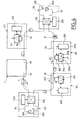
- the concentrator 1 emits simultaneously towards the ends of the fiber sections 2a, 2b of the substantially identical optical signals s1, s2 whose path is shown in Figure 1.
- a virtual cut is created between two nodes to the establishment of the network or during a reconfiguration thereof.
- This cut C is preferably located between the two adjacent nodes N3, N4 further away from concentrator 1 for example by locking the optical door 43 of node N4. There is therefore no communication between them in normal operation.
- the network according to the invention essentially organizes the traffic between the concentrator 1 on the one hand and the nodes N1 to N5 on the other hand.
- the purpose being, as described below, to protect this type of traffic.
- the invention does not prevent however not that inter-node traffic can exist simultaneously, including between the nodes located on either side of the virtual cut C, without, however, that this traffic has the same guarantee of protection in the event of fiber breakage.
- FIG. 2 represents a diagram of the network of FIG. 1 showing the transmission of downlink signals s1, s2 in a broken state R of the first fiber 2, for example located between the nodes N2 and N3.
- the optical door 43 controlled by the means 42 in relationship with the means 32 is unlocked and then authorizes the transmission optical signals s20 coming from the end 2a to the node N3 of so as to allow reception of the optical signal intended for it.
- a fraction of the signal s20 is thus taken from the fiber section 2e by bidirectional extraction means 30 then directed into the branch 31b instead of branch 31a of switch 31, controlled automatically by means 32. In this way, the direction of reception of the optical signals by the node N3 is reversed compared to the normal operating mode of the network.
- the optical door 33 also controlled by the means 33 is locked. This allows in particular in case of partial rupture leaving transmit a signal s'1 with a significant error rate (path shown in dotted line), avoid mixing it with the good quality optical signal s20.
- FIG. 3 represents the network diagram of FIG. 1 showing the normal state of transmission of an uplink signal by a second fiber of the network 6 dedicated to the transport of uplink signals.
- All communication nodes N1 to N5 are interconnected optically with the concentrator 1 via the fiber 6 which notably includes two fiber sections 6a, 6b belonging to the concentrator 1 for the reception of upstream optical signals.
- Each node N1 to N5 is capable transmit uplink signals at different wavelengths from others nodes.
- Upstream signals propagate in a direction of propagation determined according to the chosen branch of the optical switch in the transmitter node.
- the node N3 emits an upward optical signal s3 whose path in normal operation is shown in Figure 3. This signal s3 is received by the concentrator 1 via the fiber section 6b.
- FIG. 4 represents a diagram of the network of FIG. 3 showing the transmission of the uplink signal s3 in a broken state R 'of the second fiber 6, for example located between the nodes N2 and N3.
- This rupture R ' is detected and localized for example by the means 320 of node N3.
- the signal s3 is then directed into the branch 310b instead from branch 310a of switch 31, then inserted from fiber section 6e by the bidirectional extraction means 300 and finally transmitted to the concentrator 1 via the fiber section 6a instead of the fiber section 6b normal running.
- Parts 1A and 1B are interconnected by a fiber section bidirectional 2 '. Each of parts 1A, 1B is also connected to a fiber section end 2a, 2b belonging to a first fiber, this in order to inject into these sections 2a, 2b substantially optical signals identical intended for nodes of the network.
- the switches of the two parts 1A and 1B operate two to of them. Three configurations are possible and described by following the path of optical signals from their emission by the transmitters to their injection in the fiber sections 2a, 2b.
- switches In normal operation of the H1 concentrator, the switches are positioned as switches 110A, 110B respectively in crossed and direct position.
- the falling signals s1 and s2 substantially identical are emitted by the H1 concentrator with directions of propagation opposite in the fiber sections 2a, 2b while the double signals securing s'1 and s'2 are not used.
- the switches are positioned as switches 111A, 111B respectively in direct and crossed position. Since the downlink signals s3 and s4 are not reliable, the signals of double securing s'3 and s'4 are emitted by the concentrator 1 with directions of opposite propagation in the fiber sections 2a, 2b.
- the switches can also be positioned like the switches 112A, 112B that is to say in crossed positions. In that case, one of the descending signals s5, s6 emitted in part 1A is injected on the fiber section 2a. One of the s7 double secure downlink signals, s8 emitted in part 1B and identical to signal s5 is also injected on the fiber section 2b.
- FIG. 6 represents a partial view of a traffic concentrator H2 according to another preferred embodiment of the invention.
- the H2 concentrator comprises four sections of fiber 2a ', 2b', 6a ', 6b 'apartment with two separate optical fibers respectively dedicated to transport of downlink and uplink signals in the network.
- the H2 concentrator more particularly comprises two parts 2A, 2B respectively for the management of the downlink and uplink signals.
- FIGS. 7 to 9 describe more precisely an embodiment of the three-state optical switch 600 forming a quadrilateral ABCD. They generally use so-called MEM techniques for Micro-Electro-Mechanics concerning small or very small mechanical devices with electrical control.
- the optical switch 600 comprises a vertical mirror 601 and a horizontal mirror 602 moved mechanically under the action of an electrical voltage in order to orient the optical signals, and optical conduits 60A to 60D.
- a voltage 603 is applied to the horizontal mirror 602 with two reflecting faces which moves to return the optical signals from A to B and from C to D.
- This state of the switch 600 corresponds to the direct propagation mode.
- a voltage 604 is applied on the contrary to the vertical mirror 601 with two reflecting faces which moves to reflect the optical signals from A to D and from B to C.
- This state of the switch 600 corresponds to the transparent propagation mode .
- the switch 600 is at rest, in cross propagation mode, that is to say that the passage of the optical signals takes place freely, between the conduits 60A to 60D, between A and C and between B and D without any voltage having to be applied to the control pins 605 and 606.
- the two movable mirrors 601, 602 are in their rest position.
- the means of monitoring signal traffic descendants can be confused with traffic control means of up signals.
- a traffic concentrator according to the invention can comprise both two identical parts for the double securing of downlink signal traffic as described for the H1 concentrator and an interconnection fiber for the communication between downlink and uplink traffic such as described for the H2 concentrator.
- the means of routing traffic amounting to a concentrator according to the invention may include pairs of optical switches to two 2x2 states instead of three-state optical switches.
Landscapes
- Engineering & Computer Science (AREA)
- Computer Networks & Wireless Communication (AREA)
- Signal Processing (AREA)
- Physics & Mathematics (AREA)
- Electromagnetism (AREA)
- Computing Systems (AREA)
- Optical Communication System (AREA)
- Small-Scale Networks (AREA)
Applications Claiming Priority (2)
| Application Number | Priority Date | Filing Date | Title |
|---|---|---|---|
| FR0200860A FR2835134B1 (fr) | 2002-01-24 | 2002-01-24 | Methode de securisation d'un reseau de telecommunication optique en anneau ainsi que noeud de communication, noeud de communication a amplification et concentrateur de trafic d'un reseau securise de telecommunication optique en anneau |
| FR0200860 | 2002-01-24 |
Publications (2)
| Publication Number | Publication Date |
|---|---|
| EP1331748A2 true EP1331748A2 (de) | 2003-07-30 |
| EP1331748A3 EP1331748A3 (de) | 2008-12-17 |
Family
ID=8871394
Family Applications (1)
| Application Number | Title | Priority Date | Filing Date |
|---|---|---|---|
| EP03290188A Withdrawn EP1331748A3 (de) | 2002-01-24 | 2003-01-24 | Verfahren zur Sicherung eines optischen Ring-Übertragungsnetzwerks und verstärkender Kommunikationsknoten und Verkehrskonzentrator |
Country Status (6)
| Country | Link |
|---|---|
| US (1) | US20050123292A1 (de) |
| EP (1) | EP1331748A3 (de) |
| JP (1) | JP2005516468A (de) |
| CN (1) | CN1620773A (de) |
| FR (1) | FR2835134B1 (de) |
| WO (1) | WO2003063400A2 (de) |
Cited By (1)
| Publication number | Priority date | Publication date | Assignee | Title |
|---|---|---|---|---|
| EP2685652A1 (de) * | 2012-07-13 | 2014-01-15 | Nokia Solutions and Networks Oy | Flexible und ökonomische Metro-/Access-Ring-Architektur |
Families Citing this family (2)
| Publication number | Priority date | Publication date | Assignee | Title |
|---|---|---|---|---|
| CN101938319B (zh) * | 2009-07-01 | 2013-07-24 | 中国移动通信集团广西有限公司 | 一种无源光网络环网系统及信号传输方法 |
| JP2013258530A (ja) * | 2012-06-12 | 2013-12-26 | Fujitsu Ltd | 双方向モニタモジュール、光モジュール及び光分岐挿入装置 |
Family Cites Families (8)
| Publication number | Priority date | Publication date | Assignee | Title |
|---|---|---|---|---|
| EP0668674B1 (de) * | 1994-02-17 | 2003-05-21 | Kabushiki Kaisha Toshiba | Optisches Wellenlängenmultiplex Netzwerk |
| DE4430512C2 (de) * | 1994-08-27 | 2000-06-29 | Bosch Gmbh Robert | Vorrichtung zum Beschalten einer verstärkenden Faser |
| US5680235A (en) * | 1995-04-13 | 1997-10-21 | Telefonaktiebolaget Lm Ericsson | Optical multichannel system |
| DE19650088A1 (de) * | 1996-12-03 | 1998-06-04 | Alsthom Cge Alcatel | System zur gerichteten Punkt-zu-Mehrpunkt Informationsübertragung |
| SE9702685D0 (sv) * | 1997-07-11 | 1997-07-11 | Ericsson Telefon Ab L M | Self-healing ring network and a method for fault detection and rectifying |
| US6317231B1 (en) * | 1998-09-04 | 2001-11-13 | Lucent Technologies Inc. | Optical monitoring apparatus and method for network provisioning and maintenance |
| JP2004514303A (ja) * | 1999-09-03 | 2004-05-13 | オーエヌアイ システムズ コーポレイション | 光学ネットワークにおける光学パワーマネジメント |
| US6307986B1 (en) * | 2001-04-24 | 2001-10-23 | Seneca Networks | Protection switching in bidirectional WDM optical communication networks with transponders |
-
2002
- 2002-01-24 FR FR0200860A patent/FR2835134B1/fr not_active Expired - Fee Related
-
2003
- 2003-01-24 US US10/502,353 patent/US20050123292A1/en not_active Abandoned
- 2003-01-24 CN CNA038025892A patent/CN1620773A/zh active Pending
- 2003-01-24 JP JP2003563136A patent/JP2005516468A/ja not_active Ceased
- 2003-01-24 EP EP03290188A patent/EP1331748A3/de not_active Withdrawn
- 2003-01-24 WO PCT/FR2003/000230 patent/WO2003063400A2/fr active Application Filing
Cited By (2)
| Publication number | Priority date | Publication date | Assignee | Title |
|---|---|---|---|---|
| EP2685652A1 (de) * | 2012-07-13 | 2014-01-15 | Nokia Solutions and Networks Oy | Flexible und ökonomische Metro-/Access-Ring-Architektur |
| WO2014009248A1 (en) * | 2012-07-13 | 2014-01-16 | Xieon Networks S.À.R.L. | Flexible and economic metro / access ring architecture |
Also Published As
| Publication number | Publication date |
|---|---|
| CN1620773A (zh) | 2005-05-25 |
| EP1331748A3 (de) | 2008-12-17 |
| WO2003063400A2 (fr) | 2003-07-31 |
| US20050123292A1 (en) | 2005-06-09 |
| JP2005516468A (ja) | 2005-06-02 |
| FR2835134B1 (fr) | 2005-06-24 |
| FR2835134A1 (fr) | 2003-07-25 |
| WO2003063400B1 (fr) | 2004-04-15 |
| WO2003063400A3 (fr) | 2004-03-11 |
Similar Documents
| Publication | Publication Date | Title |
|---|---|---|
| EP0677936B1 (de) | Wiederkonfigurierbares optisches Mehrwellenlängen-Ringnetzwerk | |
| EP0743772B1 (de) | Ringnetzwerk mit Wellenlängenmultiplexing zur Nachrichtenübertragung | |
| EP0863634B1 (de) | Rekonfigurierbares optisches Ringübertragungsnetz mit Wellenlängenmultiplexing für halbpermanente Verbindungen | |
| EP1331748A2 (de) | Verfahren zur Sicherung eines optischen Ring-Übertragungsnetzwerks und verstärkender Kommunikationsknoten und Verkehrskonzentrator | |
| EP1292072B1 (de) | System und Verfahren zum Übermittlungsschutz in einem optischen Ringnetz ausgeführt mit einziger Glasfaser | |
| FR2694148A1 (fr) | Procédé et dispositif pour surveiller des réseaux de lignes optiques ramifiées. | |
| EP0064919A1 (de) | Vorrichtung zur Ein- und/oder Ausgabe eines optischen Signals | |
| EP1428333B1 (de) | Optisches ringnetzwerk mit doppeltem optischem bus | |
| WO2008009849A2 (fr) | Reseau optique passif longue distance utilisant la modulation deportee d'un signal optique d'amplification | |
| EP1592159B1 (de) | Optisches Übertragungsnetz mit Baumstruktur | |
| WO2005109706A1 (fr) | Procede et systeme de protection d’un reseau de communication, ledit reseau de communication incluant un reseau de transport | |
| EP1496720B1 (de) | Optisches Ringnetzwerk mit Löcherfüllungsprotokol unabhängig von der Übertragungsrate | |
| FR2810746A1 (fr) | Reseau sous-marin de transmissions par fibre optique | |
| EP1804407B1 (de) | Accessknoten für optisches Ringnetzwerk | |
| EP0509434B1 (de) | Übertragungsanlage mit fernüberwachter optischer Verbindung | |
| FR2896644A1 (fr) | Dispositif de surveillance d'un reseau optique par echometrie | |
| EP1376910A2 (de) | Optisches Ringnetzwerk mit abgekoppelten Lese- und Schreibfasern | |
| EP0471633A1 (de) | Kommunikationsnetz mit Schreib- und Lesering, und Zugriffs- und Rekonfigurationsverfahren eines solchen Netzes | |
| EP1505755A1 (de) | Verfahren und Vorrichtung zur Kontrolle einer Sicherheitsverbindung oder Verbindungswiederherstellung in einem hybriden optischen Netzwerk | |
| FR2714557A1 (fr) | Dispositif de sécurisation de liaisons optiques. | |
| EP1876743A2 (de) | Rekonfigurierbarer optischer Add-Drop-Multiplexer, mit geschützten wellenlängenselektiven Schaltern | |
| FR2598573A1 (fr) | Procede et structure pour assurer la trasmission de signaux par fibres optiques, et reseau comportant une telle structure | |
| EP1538768A2 (de) | Rekonfigurierbarer optischer Add/Drop-Multiplexer | |
| FR2771568A1 (fr) | Surveillance centralisee de liaisons a fibres optiques d'un reseau de communication | |
| WO2009001018A2 (fr) | Reseau optique longue distance avec localisation des moyens d'amplification au niveau du central optique |
Legal Events
| Date | Code | Title | Description |
|---|---|---|---|
| PUAI | Public reference made under article 153(3) epc to a published international application that has entered the european phase |
Free format text: ORIGINAL CODE: 0009012 |
|
| AK | Designated contracting states |
Designated state(s): AT BE BG CH CY CZ DE DK EE ES FI FR GB GR HU IE IT LI LU MC NL PT SE SI SK TR |
|
| AX | Request for extension of the european patent |
Extension state: AL LT LV MK RO |
|
| RAP1 | Party data changed (applicant data changed or rights of an application transferred) |
Owner name: ALCATEL LUCENT |
|
| PUAL | Search report despatched |
Free format text: ORIGINAL CODE: 0009013 |
|
| AK | Designated contracting states |
Kind code of ref document: A3 Designated state(s): AT BE BG CH CY CZ DE DK EE ES FI FR GB GR HU IE IT LI LU MC NL PT SE SI SK TR |
|
| AX | Request for extension of the european patent |
Extension state: AL LT LV MK RO |
|
| AKX | Designation fees paid | ||
| REG | Reference to a national code |
Ref country code: DE Ref legal event code: 8566 |
|
| STAA | Information on the status of an ep patent application or granted ep patent |
Free format text: STATUS: THE APPLICATION IS DEEMED TO BE WITHDRAWN |
|
| 18D | Application deemed to be withdrawn |
Effective date: 20090618 |