EP1331748A2 - Method of securing an optical ring telecommunication network and amplified communication node and traffic concentrator - Google Patents
Method of securing an optical ring telecommunication network and amplified communication node and traffic concentrator Download PDFInfo
- Publication number
- EP1331748A2 EP1331748A2 EP03290188A EP03290188A EP1331748A2 EP 1331748 A2 EP1331748 A2 EP 1331748A2 EP 03290188 A EP03290188 A EP 03290188A EP 03290188 A EP03290188 A EP 03290188A EP 1331748 A2 EP1331748 A2 EP 1331748A2
- Authority
- EP
- European Patent Office
- Prior art keywords
- network
- optical
- fiber
- signals
- transmission state
- Prior art date
- Legal status (The legal status is an assumption and is not a legal conclusion. Google has not performed a legal analysis and makes no representation as to the accuracy of the status listed.)
- Withdrawn
Links
Images


Classifications
-
- H—ELECTRICITY
- H04—ELECTRIC COMMUNICATION TECHNIQUE
- H04Q—SELECTING
- H04Q11/00—Selecting arrangements for multiplex systems
- H04Q11/0001—Selecting arrangements for multiplex systems using optical switching
- H04Q11/0062—Network aspects
-
- H—ELECTRICITY
- H04—ELECTRIC COMMUNICATION TECHNIQUE
- H04B—TRANSMISSION
- H04B10/00—Transmission systems employing electromagnetic waves other than radio-waves, e.g. infrared, visible or ultraviolet light, or employing corpuscular radiation, e.g. quantum communication
- H04B10/07—Arrangements for monitoring or testing transmission systems; Arrangements for fault measurement of transmission systems
- H04B10/075—Arrangements for monitoring or testing transmission systems; Arrangements for fault measurement of transmission systems using an in-service signal
- H04B10/079—Arrangements for monitoring or testing transmission systems; Arrangements for fault measurement of transmission systems using an in-service signal using measurements of the data signal
- H04B10/0791—Fault location on the transmission path
-
- H—ELECTRICITY
- H04—ELECTRIC COMMUNICATION TECHNIQUE
- H04B—TRANSMISSION
- H04B10/00—Transmission systems employing electromagnetic waves other than radio-waves, e.g. infrared, visible or ultraviolet light, or employing corpuscular radiation, e.g. quantum communication
- H04B10/07—Arrangements for monitoring or testing transmission systems; Arrangements for fault measurement of transmission systems
- H04B10/075—Arrangements for monitoring or testing transmission systems; Arrangements for fault measurement of transmission systems using an in-service signal
- H04B10/079—Arrangements for monitoring or testing transmission systems; Arrangements for fault measurement of transmission systems using an in-service signal using measurements of the data signal
- H04B10/0793—Network aspects, e.g. central monitoring of transmission parameters
-
- H—ELECTRICITY
- H04—ELECTRIC COMMUNICATION TECHNIQUE
- H04B—TRANSMISSION
- H04B10/00—Transmission systems employing electromagnetic waves other than radio-waves, e.g. infrared, visible or ultraviolet light, or employing corpuscular radiation, e.g. quantum communication
- H04B10/27—Arrangements for networking
- H04B10/275—Ring-type networks
- H04B10/2755—Ring-type networks with a headend
-
- H—ELECTRICITY
- H04—ELECTRIC COMMUNICATION TECHNIQUE
- H04J—MULTIPLEX COMMUNICATION
- H04J14/00—Optical multiplex systems
- H04J14/02—Wavelength-division multiplex systems
- H04J14/0278—WDM optical network architectures
- H04J14/0283—WDM ring architectures
-
- H—ELECTRICITY
- H04—ELECTRIC COMMUNICATION TECHNIQUE
- H04J—MULTIPLEX COMMUNICATION
- H04J14/00—Optical multiplex systems
- H04J14/02—Wavelength-division multiplex systems
- H04J14/0287—Protection in WDM systems
- H04J14/0289—Optical multiplex section protection
-
- H—ELECTRICITY
- H04—ELECTRIC COMMUNICATION TECHNIQUE
- H04J—MULTIPLEX COMMUNICATION
- H04J14/00—Optical multiplex systems
- H04J14/02—Wavelength-division multiplex systems
- H04J14/0287—Protection in WDM systems
- H04J14/0293—Optical channel protection
-
- H—ELECTRICITY
- H04—ELECTRIC COMMUNICATION TECHNIQUE
- H04Q—SELECTING
- H04Q11/00—Selecting arrangements for multiplex systems
- H04Q11/0001—Selecting arrangements for multiplex systems using optical switching
- H04Q11/0062—Network aspects
- H04Q2011/0079—Operation or maintenance aspects
- H04Q2011/0081—Fault tolerance; Redundancy; Recovery; Reconfigurability
-
- H—ELECTRICITY
- H04—ELECTRIC COMMUNICATION TECHNIQUE
- H04Q—SELECTING
- H04Q11/00—Selecting arrangements for multiplex systems
- H04Q11/0001—Selecting arrangements for multiplex systems using optical switching
- H04Q11/0062—Network aspects
- H04Q2011/009—Topology aspects
- H04Q2011/0092—Ring
Landscapes
- Engineering & Computer Science (AREA)
- Computer Networks & Wireless Communication (AREA)
- Signal Processing (AREA)
- Physics & Mathematics (AREA)
- Electromagnetism (AREA)
- Computing Systems (AREA)
- Optical Communication System (AREA)
- Small-Scale Networks (AREA)
Abstract
Description
La présente invention se rapporte au domaine des réseaux de télécommunication optique et décrit plus particulièrement une méthode et des dispositifs assurant la sécurisation d'un réseau de télécommunication optique en anneau.The present invention relates to the field of optical telecommunications and more particularly describes a method and devices ensuring the security of an optical telecommunications network in a ring.
De manière connue, des réseaux tels que certains réseaux métropolitains couvrant des zones géographiques assez importantes et permettant l'interconnexion de réseaux locaux par exemple situés à moins de 100 km les uns des autres, présentent une architecture de type anneau. De tels réseaux comprennent généralement :
- un concentrateur de trafic distribuant à l'intérieur du réseau des signaux optiques dits descendants multiplexés en longueurs d'onde issus du réseau fédérateur ou « backone », et recevant de l'intérieur du réseau en anneau des signaux optiques dits montants multiplexés en longueurs d'onde et les transmettant à ce réseau fédérateur,
- une fibre optique dédiée au transport des signaux descendants à l'intérieur du réseau depuis le concentrateur,
- une autre fibre optique distincte dédiée au transport des signaux montants à l'intérieur du réseau et destinés au concentrateur,
- des noeuds de communication, dits de fonctionnement, associés aux deux fibres, comprenant chacun un OADM (Optical Add/Drop Multiplexer en anglais) et aptes à dériver une partie du trafic (sélection d'une ou plusieurs longueurs d'onde du signal multiplexé descendant) pour le transmettre à un réseau local et à insérer leur propre trafic en direction du concentrateur (ajout d'une ou plusieurs longueurs d'onde dans le signal multiplexé montant) tout en laissant transiter l'ensemble des longueurs d'onde des signaux multiplexés descendants et montants,
- des noeuds de communication à amplification, comprenant également chacun un OADM ainsi que des moyens optiques d'amplification, disposés dans chacune des fibres pour recevoir et amplifier les signaux se propageant au sein du réseau en anneau.
- a traffic concentrator distributing within the network so-called downlink optical signals wavelength multiplexed from the backbone network, and receiving from inside the ring network so-called multiplexed optical signals in lengths d wave and transmitting them to this backbone network,
- an optical fiber dedicated to the transport of downlink signals within the network from the concentrator,
- another separate optical fiber dedicated to the transport of uplink signals within the network and intended for the concentrator,
- communication nodes, known as operating nodes, associated with the two fibers, each comprising an OADM (Optical Add / Drop Multiplexer in English) and capable of diverting part of the traffic (selection of one or more wavelengths of the downlink multiplexed signal ) to transmit it to a local network and to insert their own traffic towards the concentrator (addition of one or more wavelengths in the upstream multiplexed signal) while letting transit all the wavelengths of the multiplexed signals descendants and ascents,
- amplification communication nodes, each also comprising an OADM as well as optical amplification means, arranged in each of the fibers to receive and amplify the signals propagating within the ring network.
Afin d'assurer la réception par exemple des signaux descendants par le réseau local, même en cas d'interruption du réseau en anneau, les réseaux en anneau de l'art antérieur comportent une fibre supplémentaire de sécurisation ainsi qu'un noeud de communication supplémentaire de sécurisation par noeud de communication de fonctionnement, le noeud de sécurisation étant sensiblement identique à ce dernier, lié au même réseau local et associé à la fibre de sécurisation.In order to ensure the reception for example of downlink signals by the local network, even if the ring network is interrupted, the networks in the prior art ring comprise an additional fiber of security as well as an additional communication node of securing by operating communication node, the security being substantially identical to the latter, linked to the same network local and associated with the security fiber.
Plus précisément, le concentrateur de trafic duplique les signaux descendants. Une partie de ces signaux, dits de fonctionnement, sont transportés par une première fibre optique jusqu'en amont du noeud de fonctionnement suivant un sens de propagation donné. Une autre partie de ces signaux, dits de sécurisation, sont transportés par la fibre de sécurisation jusqu'en amont du noeud de sécurisation dans le sens opposé aux signaux de fonctionnement. Ensuite, des moyens d'aiguillage couplés avec la première fibre et la fibre de sécurisation activent l'un des noeuds en fonction de l'état de transmission du réseau, ceci en permettant le passage des signaux descendants de fonctionnement ou de sécurisation dans l'OADM correspondant.More specifically, the traffic concentrator duplicates the signals descendants. Some of these so-called operating signals are transported by a first optical fiber to the upstream of the operation in a given direction of propagation. Another part of these signals, known as security signals, are transported by the security fiber upstream of the security node in the opposite direction to the signals operation. Then, referral means coupled with the first fiber and the securing fiber activate one of the nodes depending on the state of network transmission, allowing signals to pass through descendants of operation or security in the OADM corresponding.
Naturellement, des noeuds de communication à amplification sont également insérés dans la fibre de sécurisation.Naturally, amplified communication nodes are also inserted in the securing fiber.
Les documents US 5.680.235 et WO 99.03230 décrivent de tels réseaux en anneau nécessitant l'utilisation de deux fibres pour permettre deux états de fonctionnement : une transmission normale et une transmission de secours, en cas de rupture de l'anneau. Documents US 5,680,235 and WO 99.03230 describe such ring networks requiring the use of two fibers to allow two operating states: normal transmission and transmission of rescue, in case of rupture of the ring.
La duplication des fibres optiques et des différents noeuds de communication, notamment des OADM et des moyens d'amplification, engageant un surcoût important, les réseaux sécurisés de l'art antérieur ne sont donc pas satisfaisants.Duplication of optical fibers and different nodes of communication, in particular OADMs and means of amplification, incurring a significant additional cost, the secure networks of the prior art do not are therefore not satisfactory.
La présente invention a pour objet de mettre au point une méthode et des dispositifs assurant à faible coût la sécurisation du trafic dans un réseau de télécommunications optiques en anneau.The object of the present invention is to develop a method and devices ensuring low-cost security of traffic in a network ring optical telecommunications.
A cet effet, la présente invention propose d'abord une méthode de
sécurisation d'un réseau de télécommunications optiques en anneau, le
réseau incluant un concentrateur de trafic et un noeud de communication
interconnectés via une fibre optique du réseau, le concentrateur émettant des
signaux optiques transportés dans la fibre et destinés au noeud,
caractérisée en ce qu'elle consiste à utiliser une même fibre dans un
sens lorsque le réseau est dans un état de transmission normal, et dans le
sens opposé lorsque le réseau est dans un état de transmission de secours.To this end, the present invention first proposes a method for securing an optical ring telecommunications network, the network including a traffic concentrator and a communication node interconnected via an optical fiber of the network, the concentrator transmitting signals. optics transported in the fiber and intended for the node,
characterized in that it consists in using the same fiber in one direction when the network is in a normal transmission state, and in the opposite direction when the network is in a backup transmission state.
Cette méthode assure ainsi la sécurisation de la transmission des signaux optiques descendants émis par le concentrateur car, en cas de rupture de l'anneau, chaque noeud du réseau va recevoir les signaux descendants, qui lui sont destinés, du côté de la fibre opposé à celui de la rupture, par rapport au noeud.This method thus secures the transmission of downlink optical signals emitted by the concentrator because, in the event of a break of the ring, each node of the network will receive the downlink signals, which are intended for it, on the side of the fiber opposite to that of the break, by relation to the node.
L'invention propose aussi un noeud de communication d'un réseau sécurisé de télécommunications optiques en anneau, comprenant :
- une section de fibre optique, pour le transport de signaux optiques,
- des moyens d'extraction pour extraire des signaux optiques transportés par la section de fibre,
et en ce qu'il comprend en outre :
- des moyens d'aiguillage pour diriger les signaux optiques extraits par les moyens d'extraction,
- des moyens de contrôle pour détecter l'état de transmission du réseau et piloter les moyens d'aiguillage en fonction de cet état.
- an optical fiber section, for the transport of optical signals,
- extraction means for extracting optical signals transported by the fiber section,
and in that it further comprises:
- switching means for directing the optical signals extracted by the extraction means,
- control means for detecting the transmission state of the network and controlling the switching means as a function of this state.
Le coupleur de puissance selon l'invention prélève une fraction du signal multiplexé en longueurs d'onde descendant au lieu de sélectionner une ou plusieurs longueurs d'onde dans ce signal comme les OADM de l'art antérieur. Un tel coupleur est moins onéreux qu'un OADM et permet de diffuser une même longueur d'onde vers plusieurs noeuds.The power coupler according to the invention takes a fraction of the signal multiplexed in falling wavelengths instead of selecting a or more wavelengths in this signal like the OADMs of art prior. Such a coupler is less expensive than an OADM and allows broadcast the same wavelength to several nodes.
De préférence, le noeud peut comprendre une porte optique, pilotée par les moyens de contrôle et insérée dans la section de fibre pour transmettre ou supprimer des signaux optiques.Preferably, the node can include an optical door, controlled by means of control and inserted into the fiber section to transmit or delete optical signals.
Par exemple, en cas de rupture partielle de la fibre, la porte optique permet la suppression totale du signal descendant résiduel de mauvaise qualité.For example, in the event of partial fiber breakage, the optical door allows total removal of the residual downlink signal from bad quality.
L'invention concerne également un noeud de communication d'un réseau sécurisé de télécommunications optiques en anneau, comprenant :
- une section de fibre optique, pour le transport de signaux optiques,
- des moyens d'insertion pour insérer des signaux optiques dans la section de fibre,
et en ce qu'il comprend en outre :
- des moyens d'aiguillage pour diriger des signaux optiques à insérer dans la section de fibre vers les moyens d'insertion,
- des moyens de contrôle pour détecter l'état de transmission du réseau et piloter les moyens d'aiguillage en fonction de cet état.
- an optical fiber section, for the transport of optical signals,
- insertion means for inserting optical signals into the fiber section,
and in that it further comprises:
- switching means for directing optical signals to be inserted into the fiber section towards the insertion means,
- control means for detecting the transmission state of the network and controlling the switching means as a function of this state.
Les moyens d'insertion selon l'invention permettent d'injecter des signaux optiques dans la section de fibre dans les deux sens de propagation.The insertion means according to the invention make it possible to inject optical signals in the fiber section in both directions of propagation.
De même, l'invention concerne un noeud de communication à amplification d'un réseau sécurisé de télécommunications optiques en anneau, comprenant :
- au moins une section de fibre optique, pour le transport de signaux optiques,
- des moyens d'amplification pour chaque section de fibre, insérés dans la section de fibre associée, pour amplifier des signaux optiques,
- des moyens d'aiguillage pour chaque section de fibre, insérés dans la section de fibre associée, pour diriger les signaux optiques vers les moyens d'amplification associés,
- des moyens de contrôle pour détecter l'état de transmission du réseau et piloter les moyens d'aiguillage en fonction de cet état.
- at least one section of optical fiber, for transporting optical signals,
- amplification means for each fiber section, inserted in the associated fiber section, for amplifying optical signals,
- switching means for each fiber section, inserted in the associated fiber section, to direct the optical signals to the associated amplification means,
- control means for detecting the transmission state of the network and controlling the switching means as a function of this state.
Avantageusement, le noeud à amplification selon l'invention peut comprendre des moyens d'extraction de type coupleur de puissance pour extraire des signaux optiques dits descendants transportés par la section de fibre du réseau dédiée au transport des signaux descendants.Advantageously, the amplification node according to the invention can include power coupler type extraction means for extract so-called downlink optical signals transported by the section of network fiber dedicated to the transport of downlink signals.
De préférence, le noeud à amplification selon l'invention peut comprendre des moyens d'insertion de type coupleur de puissance pour insérer des signaux optiques dits montants dans la section de fibre du réseau dédiée au transport des signaux montants. Preferably, the amplification node according to the invention can include insertion means of the power coupler type for insert so-called optical signals into the fiber section of the network dedicated to the transport of uplink signals.
De plus, l'invention se rapporte à un concentrateur de trafic d'un réseau sécurisé de télécommunications optiques en anneau, caractérisé en ce que, pour permettre d'utiliser une même section de fibre dans un sens lorsque le réseau est dans un état de transmission normal, et dans le sens opposé lorsque le réseau est dans un état de transmission de secours, il comprend :
- deux sections distinctes d'une première fibre optique,
- des moyens d'aiguillage connectés à l'une des extrémités de chacune des sections de la première fibre pour injecter à ces deux extrémités des signaux optiques sensiblement identiques destinés à des noeuds du réseau,
- deux sections distinctes d'une deuxième fibre optique distincte de la première fibre,
- des moyens d'aiguillage connectés à l'une des extrémités de chacune des sections de la deuxième fibre pour recevoir par l'une de ces deux extrémités un signal optique envoyé par un noeud du réseau,
- des moyens de contrôle pour détecter l'état de transmission du réseau et piloter les moyens d'aiguillage en fonction de cet état.
- two separate sections of a first optical fiber,
- switching means connected to one end of each of the sections of the first fiber to inject at these two ends substantially identical optical signals intended for nodes of the network,
- two separate sections of a second optical fiber separate from the first fiber,
- switching means connected to one of the ends of each of the sections of the second fiber to receive by one of these two ends an optical signal sent by a network node,
- control means for detecting the transmission state of the network and controlling the switching means as a function of this state.
De préférence, les moyens d'aiguillage du concentrateur peuvent comprendre des commutateurs optiques fonctionnant deux à deux et permettant de sécuriser le réseau en cas de panne au sein du concentrateur.Preferably, the concentrator switching means can include optical switches operating in pairs and to secure the network in the event of a failure within the concentrator.
Avantageusement, les moyens d'aiguillage comprennent des commutateurs optiques à trois états formant un quadripôle A, B, C, D et permettant la propagation des signaux optiques, entre les quatre pôles, selon l'un quelconque des trois modes de propagation suivants :
- entre les pôles A et B d'une part, et entre les pôles C et D d'autre part, correspondant à un mode direct de propagation;
- entre les pôles A et C d'une part, et entre les pôles B et D d'autre part, correspondant à un mode croisé de propagation;
- entre les pôles A et D, d'une part, et entre les pôles B et C d'autre part, correspondant à un mode transparent de propagation.
- between poles A and B on the one hand, and between poles C and D on the other hand, corresponding to a direct mode of propagation;
- between poles A and C on the one hand, and between poles B and D on the other hand, corresponding to a crossed mode of propagation;
- between poles A and D, on the one hand, and between poles B and C on the other, corresponding to a transparent mode of propagation.
Les caractéristiques et objets de la présente invention ressortiront de la description détaillée donnée ci-après en regard des figures annexées, présentées à titre illustratif et nullement limitatif.The characteristics and objects of the present invention will emerge from the detailed description given below with reference to the appended figures, presented for illustration and in no way limitative.
Dans ces figures :
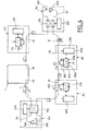
- la figure 1 représente un diagramme d'un réseau sécurisé de télécommunications optiques comprenant des noeuds dans un mode de réalisation préféré de l'invention, diagramme montrant l'état normal de transmission de signaux descendants via une première fibre du réseau,
- la figure 2 représente un diagramme du réseau de la figure 1 montrant la transmission de signaux descendants en état de rupture de la première fibre,
- la figure 3 représente le diagramme du réseau de la figure 1 montrant l'état normal de transmission d'un signal montant par une deuxième fibre du réseau,
- la figure 4 représente un diagramme du réseau de la figure 3 montrant la transmission d'un signal montant en état de rupture de la deuxième fibre,
- la figure 5 représente une vue partielle d'un concentrateur de trafic selon un mode de réalisation préféré de l'invention montrant la sécurisation de l'émission de signaux descendants,
- la figure 6 représente une vue partielle d'un concentrateur de trafic selon un autre mode de réalisation préféré de l'invention,
- les figures 7 à 9 représentent le commutateur à trois états appartenant au concentrateur de la figure 6.
- FIG. 1 represents a diagram of a secure optical telecommunications network comprising nodes in a preferred embodiment of the invention, diagram showing the normal state of transmission of downlink signals via a first fiber of the network,
- FIG. 2 represents a diagram of the network of FIG. 1 showing the transmission of downlink signals in a broken state of the first fiber,
- FIG. 3 represents the network diagram of FIG. 1 showing the normal state of transmission of an uplink signal by a second fiber of the network,
- FIG. 4 represents a diagram of the network of FIG. 3 showing the transmission of an upward signal in a broken state of the second fiber,
- FIG. 5 represents a partial view of a traffic concentrator according to a preferred embodiment of the invention showing the security of the transmission of downlink signals,
- FIG. 6 represents a partial view of a traffic concentrator according to another preferred embodiment of the invention,
- FIGS. 7 to 9 represent the three-state switch belonging to the concentrator of FIG. 6.
La figure 1 représente un diagramme d'un réseau sécurisé de télécommunications optiques comprenant des noeuds dans un mode de réalisation préféré de l'invention, diagramme montrant l'état normal de transmission de signaux descendants via une première fibre optique du réseau. Le réseau comprend :
- un concentrateur de trafic 1 émettant simultanément de chaque côté des signaux descendants multiplexés en longueurs d'onde sensiblement identiques,
- une
première fibre optique 2 dédiée au transport des signaux descendants et comprenant notamment deux sections defibre - des noeuds de communication N1, N3, N4 et à amplification N2,
N5 interconnectés optiquement avec le concentrateur 1 via
la fibre 2,
- a
traffic concentrator 1 simultaneously transmitting on each side downlink signals multiplexed in substantially identical wavelengths, - a first
optical fiber 2 dedicated to the transport of downlink signals and comprising in particular two sections offiber concentrator 1 for the injection of downlink signals into one of the ends of each of the sections, - communication nodes N1, N3, N4 and with amplification N2, N5 optically interconnected with the
concentrator 1 via thefiber 2,
Chaque noeud de communication N1, N3, N4 comprend selon l'invention :
une section fibre 2,- des moyens d'extraction bidirectionnels 10, 30, 40 de type coupleur de puissance pour extraire une fraction de la puissance des signaux optiques transitant dans le noeud via sa section de fibre,
- des moyens d'aiguillage 11, 31, 41 de type commutateur 2x1 à deux branches pour diriger les signaux extraits par les moyens d'extraction respectivement 10, 30, 40,
- des moyens de contrôle 12, 32, 42 pour détecter l'état de
transmission du réseau c'est-à-dire de la
fibre 2 et piloter les moyens d'aiguillage 11, 31, 41 en fonction de cet état, - une porte optique 13, 33, 43 pilotée par les moyens de contrôle 12, 32, 42 respectivement, pour transmettre ou supprimer des signaux optiques.
- a
section fiber 2, - bidirectional extraction means 10, 30, 40 of the power coupler type for extracting a fraction of the power of the optical signals passing through the node via its fiber section,
- switching means 11, 31, 41 of the 2x1 switch type with two branches for directing the signals extracted by the extraction means respectively 10, 30, 40,
- control means 12, 32, 42 for detecting the transmission state of the network, that is to say of the
fiber 2 and controlling the switching means 11, 31, 41 as a function of this state, - an
optical door
De plus, chaque noeud de communication à amplification N2, N5 comprend :
une section fibre 2,- des moyens d'aiguillage 21, 51, de type commutateur optique 2x2
à deux états (mode direct de propagation, mode croisé de
propagation) insérés dans la
section de fibre - des moyens de contrôle 22, 52 pour détecter l'état de transmission
du réseau c'est-à-dire de la
fibre 2 et piloter les moyens d'aiguillage 21, 51 en fonction de cet état, - des moyens d'extraction 20, 50 de type coupleur de puissance
pour extraire des signaux optiques transportés par la
section de fibre
- a
section fiber 2, - switching means 21, 51, of the 2x2 optical switch type with two states (direct propagation mode, crossed propagation mode) inserted into the
fiber section optics - control means 22, 52 for detecting the transmission state of the network, that is to say of the
fiber 2 and controlling the switching means 21, 51 as a function of this state, - extraction means 20, 50 of the power coupler type for extracting optical signals transported by the
fiber section
Ainsi le concentrateur 1 émet simultanément vers les extrémités des
sections de fibre 2a, 2b des signaux optiques s1, s2 sensiblement identiques
dont le trajet est représenté sur la figure 1. Selon une caractéristique
essentielle de l'invention, une coupure virtuelle est créée entre deux noeuds à
l'établissement du réseau ou lors d'une reconfiguration de celui-ci. Cette
coupure C est située de préférence entre les deux noeuds adjacents N3, N4 les
plus éloignés du concentrateur 1 par exemple en verrouillant la porte optique
43 du noeud N4. Il n'y donc alors aucune communication entre ces derniers
en fonctionnement normal.Thus the
Le réseau selon l'invention organise essentiellement le trafic entre le
concentrateur 1 d'une part et les noeuds N1 à N5 d'autre part. Le but étant,
comme décrit ci-après, de protéger ce type de trafic. L'invention n'empêche
cependant pas que du trafic inter noeuds puisse exister simultanément, y
compris entre les noeuds situés de part et d'autre de la coupure virtuelle C,
sans toutefois que ce trafic ait la même garantie de protection en cas de
rupture de la fibre. The network according to the invention essentially organizes the traffic between the
La figure 2 représente un diagramme du réseau de la figure 1
montrant la transmission de signaux descendants s1, s2 en état de rupture R
de la première fibre 2 par exemple située entre les noeuds N2 et N3. FIG. 2 represents a diagram of the network of FIG. 1 showing the transmission of downlink signals s1, s2 in a broken state R of the
Quand cette rupture R est détectée et localisée, par exemple par les
moyens 32 du noeud N3 la coupure virtuelle est déplacée pas à pas vers la
rupture physique R jusqu'à sa coïncidence avec cette dernière.When this rupture R is detected and located, for example by the
Dans ce but, la porte optique 43 pilotée par les moyens 42 en
relation avec les moyens 32, est déverrouillée et autorise alors la transmission
des signaux optiques s20 venant de l'extrémité 2a jusqu'au noeud N3 de
façon à permettre la réception du signal optique qui lui est destiné.For this purpose, the
Une fraction du signal s20 est ainsi prélevée de la section de fibre 2e
par les moyens d'extraction 30 bidirectionnels puis dirigée dans la branche
31b au lieu de la branche 31a du commutateur 31, piloté automatiquement
par les moyens 32. De cette façon, le sens de réception des signaux optiques
par le noeud N3 est inversé par rapport au mode de fonctionnement normal
du réseau.A fraction of the signal s20 is thus taken from the
Parallèlement, la porte optique 33 également pilotée par les moyens
33 est verrouillée. Ceci permet notamment en cas de rupture partielle laissant
transmettre un signal s'1 avec un taux d'erreur important (trajet représenté en
pointillé), d'éviter son mélange avec le signal optique s20 de bonne qualité.At the same time, the
La figure 3 représente le diagramme du réseau de la figure 1
montrant l'état normal de transmission d'un signal montant par une deuxième
fibre du réseau 6 dédiée au transport des signaux montants. FIG. 3 represents the network diagram of FIG. 1 showing the normal state of transmission of an uplink signal by a second fiber of the
Tous les noeuds de communication N1 à N5 sont interconnectés
optiquement avec le concentrateur 1 via la fibre 6 qui comprend notamment
deux sections de fibre 6a, 6b appartenant au concentrateur 1 pour la
réception de signaux optiques montants. Chaque noeud N1 à N5 est capable
d'émettre des signaux montants à des longueurs d'ondes distinctes des autres
noeuds. All communication nodes N1 to N5 are interconnected
optically with the
Chaque noeud de communication N1, N3, N4 comprend selon l'invention :
une section fibre 6,- des moyens d'insertion bidirectionnels 100, 300, 400 de type coupleur de puissance pour insérer des signaux optiques dans sa section de fibre,
- des moyens d'aiguillage 110, 310, 410 de type commutateur 2x1 à deux branches pour diriger les signaux émis vers les moyens d'insertion respectivement 100, 300, 400,
- des moyens de contrôle 120, 320, 420 pour détecter l'état de
transmission du réseau c'est-à-dire de la
fibre 6 et piloter les moyens d'aiguillage 110, 310, 410 en fonction de cet état,
- a
section fiber 6, - bidirectional insertion means 100, 300, 400 of the power coupler type for inserting optical signals into its fiber section,
- switching means 110, 310, 410 of the 2x1 switch type with two branches to direct the signals transmitted to the insertion means 100, 300, 400 respectively,
- control means 120, 320, 420 for detecting the transmission state of the network, that is to say of the
fiber 6 and controlling the switching means 110, 310, 410 as a function of this state,
De plus, chaque noeud de communication à amplification N2, N5 comprend :
une section fibre 6,- des moyens d'aiguillage 210, 510 de type commutateur optique
2x2 à deux états (mode direct de propagation, mode croisé de
propagation) insérés dans la
section de fibre - des moyens de contrôle 220, 520 pour détecter l'état de
transmission du réseau c'est-à-dire de la
fibre 6 et piloter les moyens d'aiguillage 210, 510 en fonction de cet état, - des moyens d'insertion de type coupleur de puissance 200, 500 pour insérer avant les moyens d'amplification 240, 540 des signaux optiques dans la section de fibre associée.
- a
section fiber 6, - switching means 210, 510 of the 2x2 optical switch type with two states (direct propagation mode, crossed propagation mode) inserted in the
fiber section - control means 220, 520 for detecting the transmission state of the network, that is to say of the
fiber 6 and controlling the switching means 210, 510 as a function of this state, - insertion means of the
power coupler type
Les signaux montants se propagent suivant un sens de propagation déterminé en fonction de la branche choisie du commutateur optique dans le noeud émetteur. Upstream signals propagate in a direction of propagation determined according to the chosen branch of the optical switch in the transmitter node.
A titre d'exemple, le noeud N3 émet un signal optique montant s3
dont le trajet en fonctionnement normal est représenté sur la figure 3. Ce
signal s3 est reçu par le concentrateur 1 via la section de fibre 6b.By way of example, the node N3 emits an upward optical signal s3
whose path in normal operation is shown in Figure 3. This
signal s3 is received by the
La figure 4 représente un diagramme du réseau de la figure 3
montrant la transmission du signal montant s3 en état de rupture R' de la
deuxième fibre 6 par exemple située entre les noeuds N2 et N3. FIG. 4 represents a diagram of the network of FIG. 3 showing the transmission of the uplink signal s3 in a broken state R 'of the
Cette rupture R' est détectée et localisée par exemple par les moyens
320 du noeud N3. Le signal s3 est alors dirigé dans la branche 310b au lieu
de la branche 310a du commutateur 31, puis inséré de la section de fibre 6e
par les moyens d'extraction 300 bidirectionnels et enfin transmis au
concentrateur 1 via la section de fibre 6a au lieu de la section de fibre 6b en
fonctionnement normal.This rupture R 'is detected and localized for example by the
La figure 5 représente une vue partielle d'un concentrateur selon un mode de réalisation préféré de l'invention montrant la sécurisation de l'émission de signaux descendants. Pour doubler la sécurisation du trafic descendant, le concentrateur H1 est dédoublé en deux parties 1A, 1B qui comprennent chacune:
- trois séries d'émetteurs T1A à T3B de signaux optiques à des longueurs d'onde données distinctes les unes des autres,
- un multiplexeur/démultiplexeur en longueurs d'onde M1A à M3B par série d'émetteurs, multiplexant les signaux issus d'une série d'émetteurs donnée notamment,
- un diviseur de puissance D1A à D3B par série d'émetteurs, séparant en deux signaux identiques les signaux multiplexés,
- des moyens d'aiguillage 110A à 112B pour chaque série d'émetteurs, de type commutateur optique 2x2 à deux états (mode direct de propagation, mode croisé de propagation) recevant les signaux descendants et les dirigeant vers les noeuds,
- deux multiplexeurs/démultiplexeurs Mux1A, Mux2A, Mux1B, Mux2B multiplexant les signaux issus des différentes séries d'émetteurs notamment,
- un amplificateur A1, A2 recevant les signaux multiplexés par les multiplexeurs/démultiplexeurs Mux1A, Mux2B respectivement,
- des moyens de contrôle 115 pour détecter l'état de transmission du réseau c'est-à-dire la qualité de l'émission des signaux descendants et piloter les moyens d'aiguillage 110A à 112B en fonction de cet état.
- three series of transmitters T1A to T3B of optical signals at given wavelengths distinct from each other,
- a wavelength multiplexer / demultiplexer M1A to M3B per series of transmitters, multiplexing the signals from a given series of transmitters in particular,
- a power divider D1A to D3B by series of transmitters, separating the multiplexed signals into two identical signals,
- switching means 110A to 112B for each series of transmitters, of the 2x2 optical switch type with two states (direct propagation mode, crossed propagation mode) receiving the downlink signals and directing them towards the nodes,
- two multiplexers / demultiplexers Mux1A, Mux2A, Mux1B, Mux2B multiplexing the signals from the various series of transmitters in particular,
- an amplifier A1, A2 receiving the signals multiplexed by the multiplexers / demultiplexers Mux1A, Mux2B respectively,
- control means 115 for detecting the transmission state of the network, that is to say the quality of the transmission of the downlink signals and controlling the switching means 110A to 112B as a function of this state.
Les parties 1A et 1B sont interconnectées par une section de fibre
bidirectionnelle 2'. Chacune des parties 1A, 1B est également connectée à
une extrémité de section de fibre 2a, 2b appartenant à une première fibre,
ceci afin d'injecter dans ces sections 2a, 2b des signaux optiques sensiblement
identiques destinés à des noeuds du réseau.
Le concentrateur H1 comprend également :
- deux sections de fibre appartenant à une deuxième fibre (non représentée) distincte de la première fibre optique ainsi que d'autres moyens d'aiguillage (non représentés) connectés à l'une des extrémités de chacune des sections de deuxième fibre pour recevoir par l'une de ces deux extrémités un signal optique envoyé par un noeud du réseau,
- des moyens de contrôle (non représentés) pour détecter l'état de transmission de cette deuxième fibre et piloter les moyens d'aiguillage associés en fonction de cet état.
- two sections of fiber belonging to a second fiber (not shown) distinct from the first optical fiber as well as other switching means (not shown) connected to one end of each of the sections of second fiber to receive by the 'one of these two ends an optical signal sent by a network node,
- control means (not shown) for detecting the transmission state of this second fiber and controlling the associated switching means as a function of this state.
Les commutateurs des deux parties 1A et 1B fonctionnent deux à
deux. Trois configurations sont possibles et décrites en suivant le trajet de
signaux optiques depuis leur émission par les émetteurs jusqu'à leur injection
dans les sections de fibre 2a, 2b.The switches of the two
En fonctionnement normal du concentrateur H1, les commutateurs
sont positionnés comme les commutateurs 110A, 110B respectivement en
position croisée et directe. Les signaux descendants s1 et s2 sensiblement
identiques sont émis par le concentrateur H1 avec des sens de propagation
opposés dans les sections de fibre 2a, 2b tandis que les signaux de double
sécurisation s'1 et s'2 ne sont pas utilisés.In normal operation of the H1 concentrator, the switches
are positioned as
En cas de problème d'émission, ici entre les terminaux T2A et le
multiplexeur/démultiplexeur M2A, les commutateurs sont positionnés comme
les commutateurs 111A, 111B respectivement en position directe et croisée.
Les signaux descendants s3 et s4 n'étant alors pas fiables, les signaux de
double sécurisation s'3 et s'4 sont émis par le concentrateur 1 avec des sens
de propagation opposés dans les sections de fibre 2a, 2b.In the event of a transmission problem, here between the T2A terminals and the
M2A multiplexer / demultiplexer, the switches are positioned as
Les commutateurs peuvent aussi être positionnés comme les
commutateurs 112A, 112B c'est-à-dire en positions croisées. Dans ce cas,
l'un des signaux descendants s5, s6 émis dans la partie 1A est injecté sur la
section de fibre 2a. L'un des signaux descendants de double sécurisation s7,
s8 émis dans la partie 1B et identique au signal s5 est également injecté sur la
section de fibre 2b.The switches can also be positioned like the
La figure 6 représente une vue partielle d'un concentrateur de trafic H2 selon un autre mode de réalisation préféré de l'invention. FIG. 6 represents a partial view of a traffic concentrator H2 according to another preferred embodiment of the invention.
Le concentrateur H2 comprend quatre sections de fibre 2a', 2b', 6a',
6b' appartement à deux fibres optiques distinctes dédiées respectivement au
transport de signaux descendants et montants dans le réseau.The H2 concentrator comprises four sections of
Le concentrateur H2 comprend plus particulièrement deux parties 2A,
2B respectivement pour la gestion des signaux descendants et montants.The H2 concentrator more particularly comprises two
La partie 2A comprend :
- plusieurs séries d'émetteurs T2 (une seule est représentée) de signaux optiques des longueurs d'onde données distinctes les unes des autres,
- un multiplexeur/démultiplexeur en longueurs d'onde M20A par série d'émetteurs,
- des premiers moyens
d'aiguillage 113, pour chaque série d'émetteurs, de type commutateur optique 2x1 à deux branches recevant les signaux optiques montants à retransmettre et les signaux descendants, - un diviseur de puissance par série d'émetteurs D2 séparant en deux signaux identiques les signaux multiplexés,
- des seconds moyens
d'aiguillage 114, pour chaque série d'émetteurs, de type commutateur optique 2x2 à deux états (mode direct de propagation, mode croisé de propagation) dirigeant les signaux à destination des noeuds, - deux multiplexeurs/démultiplexeurs Mux10A, Mux20A par exemple
multiplexant les signaux issus des différentes séries d'émetteurs et
injectés dans les sections de
fibres 2a', 2b', - un amplificateur A20A, inséré dans la
section de fibre 2a' recevant les signaux multiplexés par le multiplexeur/démultiplexeur Mux10A, - des moyens de contrôle (non représentés) pour détecter l'état de transmission du réseau c'est-à-dire la qualité de l'émission des signaux descendants et piloter les moyens d'aiguillage 113, 114 en fonction de cet état.
- several series of T2 transmitters (only one is shown) of optical signals of given wavelengths distinct from each other,
- one M20A wavelength multiplexer / demultiplexer per series of transmitters,
- first switching means 113, for each series of transmitters, of the 2x1 optical switch type with two branches receiving the uplink optical signals to be retransmitted and the downlink signals,
- a power divider by series of transmitters D2 separating the multiplexed signals into two identical signals,
- second switching means 114, for each series of transmitters, of the 2x2 optical switch type with two states (direct propagation mode, crossed propagation mode) directing the signals intended for the nodes,
- two multiplexers / demultiplexers Mux10A, Mux20A for example multiplexing the signals from the different series of transmitters and injected into the
fiber sections 2a ', 2b', - an amplifier A20A, inserted in the
fiber section 2a ′ receiving the signals multiplexed by the multiplexer / demultiplexer Mux10A, - control means (not shown) for detecting the transmission state of the network, that is to say the quality of the transmission of the downlink signals and controlling the switching means 113, 114 as a function of this state.
La partie 2B comprend :
- plusieurs séries de récepteurs R2 (une seule est représentée) de signaux optiques des longueurs d'onde données distinctes les unes des autres,
- un multiplexeur/démultiplexeur en longueurs d'onde M20B par série de récepteurs,
- des moyens d'aiguillage 600 pour chaque série de récepteurs, de
type commutateur optique 2x2 à trois états (mode direct de
propagation, mode croisé de propagation, mode transparent),
formant un quadripôle A, B, C, D recevant les signaux montants et
les dirigeant à destination des récepteurs R2 ou de la partie 2A via
une fibre d'interconnexion 60, - deux multiplexeurs/démultiplexeurs Mux10B, Mux20B,
- un amplificateur A20B recevant de la
section de fibre 6a' des signaux multiplexés montants, - des moyens de contrôle (non représentés) pour détecter l'état de transmission du réseau c'est-à-dire la qualité de réception des signaux montants et piloter les moyens d'aiguillage 600 en fonction de cet état.
- several series of receivers R2 (only one is shown) of optical signals of given wavelengths distinct from each other,
- a wavelength multiplexer / demultiplexer M20B per series of receivers,
- switching means 600 for each series of receivers, of the 2x2 optical switch type with three states (direct propagation mode, crossed propagation mode, transparent mode), forming a quadrupole A, B, C, D receiving the uplink signals and directing them to receivers R2 or to part 2A via an
interconnection fiber 60, - two multiplexers / demultiplexers Mux10B, Mux20B,
- an amplifier A20B receiving upstream multiplexed signals from the
fiber section 6a ', - control means (not shown) for detecting the transmission state of the network, that is to say the quality of reception of the uplink signals and controlling the switching means 600 as a function of this state.
Les figures 7 à 9 décrivent plus précisément un mode de réalisation
du commutateur optique à trois états 600 formant un quadrilatère ABCD.
Elles font appel en général aux techniques dites MEM pour Micro-Electro-Mécanique
concernant des dispositifs mécaniques de petite ou de très petite
taille à commande électrique. Le commutateur optique 600 comprend un
miroir vertical 601 et un miroir horizontal 602 déplacés mécaniquement sous
l'action d'une tension électrique afin d'orienter les signaux optiques, et des
conduits optiques 60A à 60D. FIGS. 7 to 9 describe more precisely an embodiment of the three-state
Dans la figure 7, une tension 603 est appliquée sur le miroir
horizontal 602 à deux faces réfléchissantes qui se déplace pour renvoyer les
signaux optiques de A vers B et de C vers D. Cet état du commutateur 600
correspond au mode direct de propagation.In FIG. 7 , a
Dans la figure 8, une tension 604 est appliquée au contraire sur le
miroir vertical 601 à deux faces réfléchissantes qui se déplace pour réfléchir
les signaux optiques de A vers D et de B vers C. Cet état du commutateur 600
correspond au mode transparent de propagation.In FIG. 8 , a
Dans la figure 9, le commutateur 600 est au repos, en mode croisé
de propagation, c'est-à-dire que le passage des signaux optiques se fait
librement, entre les conduits 60A à 60D, entre A et C et entre B et D sans
qu'aucune tension n'ait besoin d'être appliquée sur les broches de commande
605 et 606. Les deux miroirs mobiles 601, 602 sont dans leur position de
repos.In FIG. 9 , the
On notera bien sûr que la réalisation d'un commutateur optique tel
que décrit ci-dessus implique obligatoirement qu'une tension ne soit pas
appliquée simultanément sur les broches 605 et 606 sous peine de voir le
commutateur détruit. Ceci sera aisément contrôlé par l'intermédiaire d'un
circuit logique du type OU exclusif (non représenté) qui empêche que les deux
miroirs 601, 602 puissent être effectivement activés simultanément.It will of course be noted that the production of an optical switch such
that described above necessarily implies that a tension is not
applied simultaneously on
Bien entendu, la description qui précède a été donnée à titre purement illustratif. On pourra sans sortir du cadre de l'invention remplacer tout moyen par un moyen équivalent.Of course, the above description has been given as purely illustrative. Without departing from the scope of the invention, it is possible to replace any means by equivalent means.
En particulier, les moyens de contrôle du trafic de signaux descendants peuvent être confondus avec les moyens de contrôle du trafic de signaux montants.In particular, the means of monitoring signal traffic descendants can be confused with traffic control means of up signals.
De plus, un concentrateur de trafic selon l'invention peut comprendre à la fois deux parties identiques pour la double sécurisation du trafic des signaux descendants telles que décrites pour le concentrateur H1 et une fibre d'interconnexion pour la communication entre trafic descendant et montant telle que décrite pour le concentrateur H2.In addition, a traffic concentrator according to the invention can comprise both two identical parts for the double securing of downlink signal traffic as described for the H1 concentrator and an interconnection fiber for the communication between downlink and uplink traffic such as described for the H2 concentrator.
Les moyens d'aiguillage du trafic montant d'un concentrateur selon l'invention peuvent comprendre des paires de commutateurs optiques à deux états 2x2 au lieu de commutateurs optiques à trois états.The means of routing traffic amounting to a concentrator according to the invention may include pairs of optical switches to two 2x2 states instead of three-state optical switches.
Claims (10)
caractérisée en ce qu'elle consiste à utiliser une même fibre dans un sens (s1) lorsque le réseau est dans un état de transmission normal, et dans le sens opposé (s2) lorsque le réseau est dans un état de transmission de secours.Method for securing an optical ring telecommunications network, the network including a traffic concentrator (1) and a communication node (N3) interconnected via an optical fiber (2) of the network, the concentrator emitting optical signals (s1 , s2) transported in the fiber and intended for the node,
characterized in that it consists in using the same fiber in one direction (s1) when the network is in a normal transmission state, and in the opposite direction (s2) when the network is in a backup transmission state.
et en ce qu'il comprend en outre :
and in that it further comprises:
et en ce qu'il comprend en outre :
and in that it further comprises:
Applications Claiming Priority (2)
| Application Number | Priority Date | Filing Date | Title |
|---|---|---|---|
| FR0200860 | 2002-01-24 | ||
| FR0200860A FR2835134B1 (en) | 2002-01-24 | 2002-01-24 | SECURITY METHOD OF AN OPTICAL RING TELECOMMUNICATION NETWORK AS WELL AS A COMMUNICATION NODE, AMPLIFICATION COMMUNICATION NODE AND TRAFFIC CONCENTRATOR OF A SECURE RING OPTICAL TELECOMMUNICATION NETWORK |
Publications (2)
| Publication Number | Publication Date |
|---|---|
| EP1331748A2 true EP1331748A2 (en) | 2003-07-30 |
| EP1331748A3 EP1331748A3 (en) | 2008-12-17 |
Family
ID=8871394
Family Applications (1)
| Application Number | Title | Priority Date | Filing Date |
|---|---|---|---|
| EP03290188A Withdrawn EP1331748A3 (en) | 2002-01-24 | 2003-01-24 | Method of securing an optical ring telecommunication network and amplified communication node and traffic concentrator |
Country Status (6)
| Country | Link |
|---|---|
| US (1) | US20050123292A1 (en) |
| EP (1) | EP1331748A3 (en) |
| JP (1) | JP2005516468A (en) |
| CN (1) | CN1620773A (en) |
| FR (1) | FR2835134B1 (en) |
| WO (1) | WO2003063400A2 (en) |
Cited By (1)
| Publication number | Priority date | Publication date | Assignee | Title |
|---|---|---|---|---|
| EP2685652A1 (en) * | 2012-07-13 | 2014-01-15 | Nokia Solutions and Networks Oy | Flexible and economic Metro / Access Ring architecture |
Families Citing this family (2)
| Publication number | Priority date | Publication date | Assignee | Title |
|---|---|---|---|---|
| CN101938319B (en) * | 2009-07-01 | 2013-07-24 | 中国移动通信集团广西有限公司 | Passive optical network (PON) ring network system and signal transmission method |
| JP2013258530A (en) * | 2012-06-12 | 2013-12-26 | Fujitsu Ltd | Bidirectional monitor module, optical module, and optical add-drop multiplexer |
Citations (4)
| Publication number | Priority date | Publication date | Assignee | Title |
|---|---|---|---|---|
| EP0668674A2 (en) * | 1994-02-17 | 1995-08-23 | Kabushiki Kaisha Toshiba | Optical wavelength division multiplexed network system |
| US5680235A (en) * | 1995-04-13 | 1997-10-21 | Telefonaktiebolaget Lm Ericsson | Optical multichannel system |
| US5694238A (en) * | 1994-08-27 | 1997-12-02 | Robert Bosch Gmbh | Device for interconnecting an amplifying fiber |
| EP0847160A2 (en) * | 1996-12-03 | 1998-06-10 | Alcatel | System for directed point-multipoint information transmission |
Family Cites Families (4)
| Publication number | Priority date | Publication date | Assignee | Title |
|---|---|---|---|---|
| SE9702685D0 (en) * | 1997-07-11 | 1997-07-11 | Ericsson Telefon Ab L M | Self-healing ring network and a method for fault detection and rectifying |
| US6317231B1 (en) * | 1998-09-04 | 2001-11-13 | Lucent Technologies Inc. | Optical monitoring apparatus and method for network provisioning and maintenance |
| CN1399823A (en) * | 1999-09-03 | 2003-02-26 | Ciena公司 | Optical power management in optical network |
| US6307986B1 (en) * | 2001-04-24 | 2001-10-23 | Seneca Networks | Protection switching in bidirectional WDM optical communication networks with transponders |
-
2002
- 2002-01-24 FR FR0200860A patent/FR2835134B1/en not_active Expired - Fee Related
-
2003
- 2003-01-24 US US10/502,353 patent/US20050123292A1/en not_active Abandoned
- 2003-01-24 CN CNA038025892A patent/CN1620773A/en active Pending
- 2003-01-24 EP EP03290188A patent/EP1331748A3/en not_active Withdrawn
- 2003-01-24 JP JP2003563136A patent/JP2005516468A/en not_active Ceased
- 2003-01-24 WO PCT/FR2003/000230 patent/WO2003063400A2/en active Application Filing
Patent Citations (4)
| Publication number | Priority date | Publication date | Assignee | Title |
|---|---|---|---|---|
| EP0668674A2 (en) * | 1994-02-17 | 1995-08-23 | Kabushiki Kaisha Toshiba | Optical wavelength division multiplexed network system |
| US5694238A (en) * | 1994-08-27 | 1997-12-02 | Robert Bosch Gmbh | Device for interconnecting an amplifying fiber |
| US5680235A (en) * | 1995-04-13 | 1997-10-21 | Telefonaktiebolaget Lm Ericsson | Optical multichannel system |
| EP0847160A2 (en) * | 1996-12-03 | 1998-06-10 | Alcatel | System for directed point-multipoint information transmission |
Non-Patent Citations (3)
| Title |
|---|
| GLANCE B ET AL: "OPTICALLY RESTORABLE WDM RING NETWORK USING SIMPLE ADD/DROP CIRCUITRY" JOURNAL OF LIGHTWAVE TECHNOLOGY, IEEE. NEW YORK, US, vol. 14, no. 11, 1 novembre 1996 (1996-11-01), pages 2453-2456, XP000642008 ISSN: 0733-8724 * |
| ITO K ET AL: "Bidirectional fibre optic loop-structured network" Electronics Letters UK, vol. 17, no. 2, 22 janvier 1981 (1981-01-22), pages 84-86, XP002502852 ISSN: 0013-5194 * |
| JOHANSSON B S ET AL: "Flexible bus: A self-restoring optical ADM ring architecture" ELECTRONICS LETTERS, IEE STEVENAGE, GB, vol. 32, no. 25, 5 décembre 1996 (1996-12-05), pages 2338-2339, XP006006086 ISSN: 0013-5194 * |
Cited By (2)
| Publication number | Priority date | Publication date | Assignee | Title |
|---|---|---|---|---|
| EP2685652A1 (en) * | 2012-07-13 | 2014-01-15 | Nokia Solutions and Networks Oy | Flexible and economic Metro / Access Ring architecture |
| WO2014009248A1 (en) * | 2012-07-13 | 2014-01-16 | Xieon Networks S.À.R.L. | Flexible and economic metro / access ring architecture |
Also Published As
| Publication number | Publication date |
|---|---|
| US20050123292A1 (en) | 2005-06-09 |
| JP2005516468A (en) | 2005-06-02 |
| FR2835134B1 (en) | 2005-06-24 |
| WO2003063400A3 (en) | 2004-03-11 |
| WO2003063400B1 (en) | 2004-04-15 |
| CN1620773A (en) | 2005-05-25 |
| WO2003063400A2 (en) | 2003-07-31 |
| EP1331748A3 (en) | 2008-12-17 |
| FR2835134A1 (en) | 2003-07-25 |
Similar Documents
| Publication | Publication Date | Title |
|---|---|---|
| EP0743772B1 (en) | Transmission ring network with wavelength multiplexing | |
| EP0677936A1 (en) | Reconfigurable multiwavelength optical ring network | |
| FR2956937A1 (en) | WAVELENGTH MULTIPLEXING OPTICAL NETWORK ELEMENT | |
| FR2759834A1 (en) | RECONFIGURABLE RING TRANSMISSION NETWORK WITH WAVELENGTH MULTIPLEXING FOR SEMI-PERMANENT LINKS | |
| EP1592159B1 (en) | Optical transmission network with tree structure | |
| EP1331748A2 (en) | Method of securing an optical ring telecommunication network and amplified communication node and traffic concentrator | |
| JP2005533437A (en) | Distributed Raman amplifier and method for optical networks | |
| EP1428333B1 (en) | Ring network made using a dual optical data bus | |
| EP1292072B1 (en) | System and method for transmission protection in an optical ring built with a single optical fiber | |
| EP1743441B1 (en) | Method and system for protecting a communications network comprising a transport network | |
| EP2050213A2 (en) | Long-distance passive optical network using the off-site modulation of an optical amplifying signal | |
| FR2694148A1 (en) | Method and device for monitoring branched optical line networks | |
| EP1494383A1 (en) | WDM optical ring network for signal transmission protected by local state switching caused by local detection of interrutpion | |
| EP1496720B1 (en) | Optical ring network with void filling protocol independent of the transmission rate | |
| EP1804407B1 (en) | Acces node for optical ring network | |
| WO2001099319A1 (en) | Submarine optical fibre transmission network | |
| EP0275779B1 (en) | Directional relay protective device consisting of several types | |
| FR2523384A1 (en) | OPTICAL FIBER DATA TRANSMISSION INSTALLATION | |
| EP1376910A2 (en) | Optical ring network with uncoupled reading and writing fibers | |
| FR2714557A1 (en) | Back=up for optical fibre lines with transmitters and receivers | |
| EP1505755A1 (en) | Method and apparatus for the control of protection paths or path recovery in a hybrid optical network | |
| EP1505750B1 (en) | Method, apparatus and system for protection of an optical network with a ring-shaped topology | |
| FR2598573A1 (en) | Method and structure for ensuring the transmission of signals by optical fibres, and network containing such a structure | |
| EP1876743A2 (en) | Reconfigurable optical add/drop multiplexer containing protected wavelength selective switches | |
| EP1538768A2 (en) | Reconfigurable optical add-drop multiplexer |
Legal Events
| Date | Code | Title | Description |
|---|---|---|---|
| PUAI | Public reference made under article 153(3) epc to a published international application that has entered the european phase |
Free format text: ORIGINAL CODE: 0009012 |
|
| AK | Designated contracting states |
Designated state(s): AT BE BG CH CY CZ DE DK EE ES FI FR GB GR HU IE IT LI LU MC NL PT SE SI SK TR |
|
| AX | Request for extension of the european patent |
Extension state: AL LT LV MK RO |
|
| RAP1 | Party data changed (applicant data changed or rights of an application transferred) |
Owner name: ALCATEL LUCENT |
|
| PUAL | Search report despatched |
Free format text: ORIGINAL CODE: 0009013 |
|
| AK | Designated contracting states |
Kind code of ref document: A3 Designated state(s): AT BE BG CH CY CZ DE DK EE ES FI FR GB GR HU IE IT LI LU MC NL PT SE SI SK TR |
|
| AX | Request for extension of the european patent |
Extension state: AL LT LV MK RO |
|
| AKX | Designation fees paid | ||
| REG | Reference to a national code |
Ref country code: DE Ref legal event code: 8566 |
|
| STAA | Information on the status of an ep patent application or granted ep patent |
Free format text: STATUS: THE APPLICATION IS DEEMED TO BE WITHDRAWN |
|
| 18D | Application deemed to be withdrawn |
Effective date: 20090618 |