EP1331403A1 - Dispositif de commande d'aube variable - Google Patents
Dispositif de commande d'aube variable Download PDFInfo
- Publication number
- EP1331403A1 EP1331403A1 EP03290059A EP03290059A EP1331403A1 EP 1331403 A1 EP1331403 A1 EP 1331403A1 EP 03290059 A EP03290059 A EP 03290059A EP 03290059 A EP03290059 A EP 03290059A EP 1331403 A1 EP1331403 A1 EP 1331403A1
- Authority
- EP
- European Patent Office
- Prior art keywords
- pivot
- link
- face
- blade
- lateral faces
- Prior art date
- Legal status (The legal status is an assumption and is not a legal conclusion. Google has not performed a legal analysis and makes no representation as to the accuracy of the status listed.)
- Granted
Links
- 210000002105 tongue Anatomy 0.000 claims description 14
- 230000000694 effects Effects 0.000 claims description 12
- 230000000284 resting effect Effects 0.000 claims description 4
- 230000008878 coupling Effects 0.000 abstract 1
- 238000010168 coupling process Methods 0.000 abstract 1
- 238000005859 coupling reaction Methods 0.000 abstract 1
- 125000006850 spacer group Chemical group 0.000 description 3
- 230000010287 polarization Effects 0.000 description 2
- 230000000295 complement effect Effects 0.000 description 1
- 230000001627 detrimental effect Effects 0.000 description 1
- 230000014759 maintenance of location Effects 0.000 description 1
- 238000012986 modification Methods 0.000 description 1
- 230000004048 modification Effects 0.000 description 1
- 230000001360 synchronised effect Effects 0.000 description 1
Images



Classifications
-
- F—MECHANICAL ENGINEERING; LIGHTING; HEATING; WEAPONS; BLASTING
- F01—MACHINES OR ENGINES IN GENERAL; ENGINE PLANTS IN GENERAL; STEAM ENGINES
- F01D—NON-POSITIVE DISPLACEMENT MACHINES OR ENGINES, e.g. STEAM TURBINES
- F01D17/00—Regulating or controlling by varying flow
- F01D17/10—Final actuators
- F01D17/12—Final actuators arranged in stator parts
- F01D17/14—Final actuators arranged in stator parts varying effective cross-sectional area of nozzles or guide conduits
- F01D17/16—Final actuators arranged in stator parts varying effective cross-sectional area of nozzles or guide conduits by means of nozzle vanes
- F01D17/162—Final actuators arranged in stator parts varying effective cross-sectional area of nozzles or guide conduits by means of nozzle vanes for axial flow, i.e. the vanes turning around axes which are essentially perpendicular to the rotor centre line
-
- F—MECHANICAL ENGINEERING; LIGHTING; HEATING; WEAPONS; BLASTING
- F01—MACHINES OR ENGINES IN GENERAL; ENGINE PLANTS IN GENERAL; STEAM ENGINES
- F01D—NON-POSITIVE DISPLACEMENT MACHINES OR ENGINES, e.g. STEAM TURBINES
- F01D17/00—Regulating or controlling by varying flow
- F01D17/10—Final actuators
- F01D17/12—Final actuators arranged in stator parts
- F01D17/14—Final actuators arranged in stator parts varying effective cross-sectional area of nozzles or guide conduits
- F01D17/16—Final actuators arranged in stator parts varying effective cross-sectional area of nozzles or guide conduits by means of nozzle vanes
-
- F—MECHANICAL ENGINEERING; LIGHTING; HEATING; WEAPONS; BLASTING
- F04—POSITIVE - DISPLACEMENT MACHINES FOR LIQUIDS; PUMPS FOR LIQUIDS OR ELASTIC FLUIDS
- F04D—NON-POSITIVE-DISPLACEMENT PUMPS
- F04D29/00—Details, component parts, or accessories
- F04D29/40—Casings; Connections of working fluid
- F04D29/52—Casings; Connections of working fluid for axial pumps
- F04D29/54—Fluid-guiding means, e.g. diffusers
- F04D29/56—Fluid-guiding means, e.g. diffusers adjustable
- F04D29/563—Fluid-guiding means, e.g. diffusers adjustable specially adapted for elastic fluid pumps
-
- Y—GENERAL TAGGING OF NEW TECHNOLOGICAL DEVELOPMENTS; GENERAL TAGGING OF CROSS-SECTIONAL TECHNOLOGIES SPANNING OVER SEVERAL SECTIONS OF THE IPC; TECHNICAL SUBJECTS COVERED BY FORMER USPC CROSS-REFERENCE ART COLLECTIONS [XRACs] AND DIGESTS
- Y10—TECHNICAL SUBJECTS COVERED BY FORMER USPC
- Y10T—TECHNICAL SUBJECTS COVERED BY FORMER US CLASSIFICATION
- Y10T403/00—Joints and connections
- Y10T403/32—Articulated members
- Y10T403/32008—Plural distinct articulation axes
- Y10T403/32057—Angular and linear
- Y10T403/32073—Pivot stud slidable in elongated opening
-
- Y—GENERAL TAGGING OF NEW TECHNOLOGICAL DEVELOPMENTS; GENERAL TAGGING OF CROSS-SECTIONAL TECHNOLOGIES SPANNING OVER SEVERAL SECTIONS OF THE IPC; TECHNICAL SUBJECTS COVERED BY FORMER USPC CROSS-REFERENCE ART COLLECTIONS [XRACs] AND DIGESTS
- Y10—TECHNICAL SUBJECTS COVERED BY FORMER USPC
- Y10T—TECHNICAL SUBJECTS COVERED BY FORMER US CLASSIFICATION
- Y10T403/00—Joints and connections
- Y10T403/32—Articulated members
- Y10T403/32114—Articulated members including static joint
- Y10T403/32163—Articulate joint intermediate end joints
- Y10T403/32172—Variable angle
-
- Y—GENERAL TAGGING OF NEW TECHNOLOGICAL DEVELOPMENTS; GENERAL TAGGING OF CROSS-SECTIONAL TECHNOLOGIES SPANNING OVER SEVERAL SECTIONS OF THE IPC; TECHNICAL SUBJECTS COVERED BY FORMER USPC CROSS-REFERENCE ART COLLECTIONS [XRACs] AND DIGESTS
- Y10—TECHNICAL SUBJECTS COVERED BY FORMER USPC
- Y10T—TECHNICAL SUBJECTS COVERED BY FORMER US CLASSIFICATION
- Y10T403/00—Joints and connections
- Y10T403/50—Bridged by diverse connector
-
- Y—GENERAL TAGGING OF NEW TECHNOLOGICAL DEVELOPMENTS; GENERAL TAGGING OF CROSS-SECTIONAL TECHNOLOGIES SPANNING OVER SEVERAL SECTIONS OF THE IPC; TECHNICAL SUBJECTS COVERED BY FORMER USPC CROSS-REFERENCE ART COLLECTIONS [XRACs] AND DIGESTS
- Y10—TECHNICAL SUBJECTS COVERED BY FORMER USPC
- Y10T—TECHNICAL SUBJECTS COVERED BY FORMER US CLASSIFICATION
- Y10T403/00—Joints and connections
- Y10T403/54—Flexible member is joint component
Definitions
- the present invention relates to the control of angle blades variable setting. It finds a particular application in the field aeronautics, especially for controlling angular positions air inlet guide vanes in turbomachine compressors, such as aircraft turbomachines.
- Known devices for controlling wedging vanes variable in a turbomachine usually include a control in the form of a ring surrounding a casing of the turbomachine and a plurality of levers or links, each link having a first end connected to the control ring by a articulation and a second end mounted on the pivot of a blade respectively.
- Synchronized modification of the angular position of the blades is produced by rotation of the ring around the axis of the turbomachine.
- the link between each link and the ring includes at least one degree of freedom in rotation about an axis directed substantially radially with respect to the ring.
- the link being rigidly mounted on the pivot of the corresponding dawn, the rotation of the ring induces other movements relative between the ring and the part of the rod mounted on the pivot dawn.
- connection in the form of a ball joint or the like which, in addition to rotation around a substantially radial axis relative to the ring, allows a rotation about an axis having a substantially circumferential direction relative to the ring. It has also been proposed to make a connection offering an additional degree of freedom in translation in a substantially radial direction relative to the ring.
- the present invention therefore aims to overcome such drawbacks by proposing a control device using fixing means of the link which allow it to be held without play on the pivot of dawn.
- An object of the invention is also to remove the imprecision drive.
- variable setting angle for compressor rectifier turbomachine comprising a rod, connecting means forming articulation between a first end of the link and a ring of control, and means for fixing a second end of the rod on a pivot of a blade to be controlled, characterized in that it further comprises pinching means acting transversely relative to a median longitudinal plane of the rod to lock in rotation without play the second end of the link on the pivot.
- the clamping means comprise a clamping cap applied to the second end of the link and subjected to a force of axial tightening under the effect of the fixing means.
- This tightening cap has a radial passage which has at least one internal lateral face which is inclined with respect to a median longitudinal plane of this passage and which cooperates with a side face of the second end of the link to produce the pinch force.
- the tightening cap can exert this pinching force directly on at least one corresponding inclined lateral face of the second end of the link or through contact elements interposed between at least one inclined internal lateral face of the cap clamping and a corresponding side face of the second end of the link.
- the contact elements can be either in the form of minus one flexible tongue protruding longitudinally on one side a central block of the pivot, or at least one shim interposed between the clamping cap and a side face of the second end of the link.
- the second end of the link can have a cross section U-shaped with two wings applied against lateral surfaces of a central block of the pivot.
- the fixing means may include a through screw successively a first orifice formed in the second end of the connecting rod, a second orifice formed in the clamping cap and a third orifice formed in the pivot of the dawn.
- the means of fixing can be composed of a screw-nut system comprising a threaded rod secured to the pivot of the blade and onto which is screwed a axial tightening.
- FIG. 1 very partially represents part of turbomachine, for example of an airplane turbojet, provided with blades 2 to variable setting angle. These blades are for example blades turbomachine compressor input guidelines, distributed around of the axis of the turbomachine. In this figure 1, only one blade is represented.
- each link 20 comprises a first end 20a connected to the control ring 4 by means of connection forming articulation.
- this articulation is carried out by an axis or finger 8 passing through the first end 20a of the link 20 and engaged in a radial housing 10 of the control ring 4.
- a second end 20b of the link 20 is mounted on a pivot 30 of the blade 2 by means of fixing means 12.
- fixing means 12 conventionally comprise an attached screw 14 and a self-locking sleeve (not shown) located in the pivot of dawn. If the height of the blade pivot does not allow the fitting of a socket self-braking, it is also possible to provide fixing means under the form of a screw-nut system (not shown) comprising a rod threaded integral with the blade pivot and onto which is screwed a axial tightening.
- pinching means act transversely to a median longitudinal plane P of the link to block in rotation without play the second end 20b of the rod 20 on the pivot of the blade.
- These pinch means have a tightening cap 40 applied to the second end 20b of the rod 20 and on the pivot of the blade by the fixing means 12.
- the end 20b of the link and the pivot 30 of the blade are in abutment transverse mutual by lateral faces substantially parallel to the plane P.
- the cap 40 has at least one internal lateral face inclined by relation to the median longitudinal plane P of the link which cooperates with a corresponding inclined face of the second end 20b of the link or pivot 30 or a contact element interposed between the part end 20b of the link and pivot 30. Under the effect of axial tightening of the cap 40, the inclined faces cooperate with each other to produce the transverse pinching force of the end 20b of the rod on the dawn pivot.
- pinching means
- the pivot 30 of the blade of the device control comprises a rigid lateral part 31 projecting longitudinally from an upper face 32 of the pivot 30 to vicinity of an edge thereof.
- This rigid part is made in one single piece with pivot 30, has an internal flat side face 31a substantially parallel to the plane P and a planar external lateral face 31b which is inclined relative to the plane P.
- the internal flat lateral face 31a of the rigid part can also be slightly inclined with respect to the plane P to allow better retention of the rod 20 on the pivot 30.
- the second end 20b of the rod 20 has an orifice 21 in which engages the screw 14 (or a threaded rod integral with the pivot of dawn) with play and rests on the face 32 of the pivot 30.
- This end 20b of the link has a first side face 22a which is substantially parallel to the longitudinal median plane P of the link and which rests on the internal flat lateral face 31a of the rigid part 31, and a second side face 22b which is inclined relative to the plane P.
- this surface can for example make an angle between 15 ° and 30 ° with the plane P.
- the tightening cap 40 comprises a part which is substantially cylindrical 42 extended at its lower part by a flange 44. At its upper part, the cap 40 has an orifice 46 in which engages the screw 14 (or the threaded rod).
- a transverse passage 48 is formed in the cylindrical part 42 of the cap for housing the second end 20b of the rod 20 and the rigid part 31 of the pivot 30.
- the passage 48 is bordered by two inclined lateral faces 48a, 48b having inclinations corresponding to those of the faces 22b, 31b and building on these.
- the screw 14 is introduced successively into the orifice 46 of the clamping cap, in hole 21 of the second end of the rod and in an orifice (not shown) made axially in the dawn pivot.
- the threaded rod integral of the blade pivot also passes through the orifice 21 of the second end of the rod and the orifice 46 of the tightening cap.
- a pinch transverse is exerted and allows to apply the faces 31a, 22a one against the other thus ensuring a rotation connection without play between the rod 20 and pivot 30 of the blade.
- the cap 40 has a shape which is substantially symmetrical exerting a symmetrical pinching force with the two inclined lateral faces 48a, 48b bordering the passage 48.
- the lateral face 48a can be inclined to cooperate with the face 22b of the second end 20b of the link, the other face 48b being parallel to the plane P, as well as the face 31b.
- the pivot 30 of the blade of the device command further comprises, compared to the first embodiment described above, a flexible lateral tab 33 projecting longitudinally from the upper face 32 of the pivot 30 and arranged substantially symmetrical to the rigid part 31 relative to the plane longitudinal median P of the link.
- This flexible tab 33 is made in one piece with pivot 30 and has a side face internal 33a substantially parallel to the plane P and an external lateral face 33b inclined with respect to the plane P.
- the second end 20b of the rod 20 rests on the face upper 32 of the pivot 30.
- the first lateral face 22a of the end 20b of the rod is parallel to the plane P and rests on the lateral face internal 31a of the rigid part 31, and the second lateral face 22b of this same end 20b is also parallel to the plane P and rests on the internal lateral face 33a of the flexible tongue 33.
- the screw 14 is introduced successively into the orifice 46 of the clamping cap, in hole 21 of the second end of the rod and in the hole made in the pivot of the blade.
- the threaded rod integral with the pivot of the blade crosses also the orifice 21 of the second end of the link and the orifice 46 of the tightening cap.
- the cap 40 has a transverse passage 48 formed in the part cylindrical 42 of the cap with two inclined lateral faces 48a, 48b which have inclinations corresponding to those of the faces 33b, 31b and build on these.
- the lateral face inclined outer 33b of the flexible tongue 33 and the inclined side face 48a of the passage 48 of the tightening cap 40 have been shown planar.
- these two faces are substantially conical.
- the external lateral face 31b of the part rigid 31 and the inclined side face 48b of the passage 48 of the cap weaning 40 can also be substantially tapered.
- the pivot 30 of the blade of the control device has two slots 34a, 34b substantially parallel to the plane P and formed between a central block 35 pivot 30 and two thinned side parts 36a, 36b forming tongues Flexible. These thinned side parts each have a face lateral lateral, respectively 37a and 37b, inclined relative to the plane longitudinal median P of the link.
- the second end 20b of the rod 20 rests on the face upper 32 of the central block 35 of the pivot 30.
- This end 20b has a U-shaped section with two wings 24a and 24b engaged respectively in the slots 34a, 34b of the pivot 30 of the blade.
- the screw 14 is introduced successively into the orifice 46 of the clamping cap, in hole 21 of the second end of the rod and in the hole made in the pivot of the blade.
- the threaded rod integral with the pivot of the blade crosses also the orifice 21 of the second end of the link and the orifice 46 of the tightening cap.
- the two inclined lateral faces 48a, 48b of the passage 48 formed in its cylindrical part 42 have inclinations corresponding to those of the inclined external lateral faces 37a, 37b of the flexible tongues 36a, 36b and are supported thereon.
- the inclined lateral faces 48a, 48b of the cap 40 exert a support on the inclined lateral faces 37a, 37b flexible tabs in order to obtain a transverse pinching force wings 24a, 24b of the second end 20b of the link in the slots 34a, 34b of the dawn pivot.
- the inclined lateral faces 37a, 37b of the flexible tongues allow this clamping force generated by the means to be transmitted fixing 12 symmetrically with respect to the plane P.
- the link 20 is therefore locked in rotation without play on the pivot 30 of the blade.
- the pivot 30 of the blade of the device control has a block 35 with two flat side faces 38a, 38b substantially parallel to the plane P and symmetrical with respect to this same plan P.
- the second end 20b of the rod 20 rests on the face upper 32 of block 35.
- This end 20b has a shape with U-section with two wings 24a, 24b which rest on the side faces corresponding planes 38a, 38b of the pivot 30 of the blade.
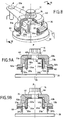
- Wedges 50a, 50b are interposed between the lateral faces inclined 48a, 48b of the transverse passage 48 formed in the part cylindrical 42 of the tightening cap 40 and the wings 24a, 24b of the second end 20b of the link.
- These wedges 50a, 50b include, in their upper part, first external lateral faces 51a, 51b inclined with respect to the plane P.
- the screw 14 is introduced successively into the orifice 46 of the clamping cap, in hole 21 of the second end of the rod and in the hole made in the pivot of the blade.
- the threaded rod integral with the pivot of the blade crosses also the orifice 21 of the second end of the link and the orifice 46 of the tightening cap.
- the two inclined lateral faces 48a, 48b of the passage 48 formed in its cylindrical part 42 have inclinations corresponding to those of the first lateral faces inclined external 51a, 51b of the wedges 50a, 50b and rest on them.
- a transverse pinching force wings 24a, 24b of the second end 20b of the link on the flat lateral faces 38a, 38b of the pivot 30 is exerted by pressing the faces inclined side 48a, 48b of the cap 40 on the shims 50a, 50b.
- the clamping cap 40 thus exerts an indirect clamping force on the second end 20b of the rod 20 by resting on the first external lateral faces 51a, 51b of the shims.
- the rod 20 is therefore blocked in rotation without play on the pivot 30 of the blade.
- the shims 50a, 50b advantageously have, in their lower part, seconds external lateral faces 52a, 52b resting on faces corresponding to pivot 30 of dawn.
- These second side faces 52a, 52b are preferably inclined relative to the plane P and have inclinations of angles opposite to those of the first faces inclined external lateral 51a, 51b, for example symmetrical thereof relative to a median transverse plane of the wedges 50a, 50b.
- the faces inclined side 52a, 52b are supported on inclined faces corresponding formed in grooves 39a, 39b which border the block central 35 of the pivot.
- the wedges 50a, 50b are maintained thanks to which the clamping force of the clamping cap is exerted in a direction substantially normal to the flat lateral faces 38a, 38b of the dawn pivot and at a height that depends on the design of the wedges 50a, 50b (angle value of their inclined faces, choice of their positioning in the assembly Vietnamese).
- the first external lateral face 51a, 51b of each of the two shims 50a, 50b is of substantially curvilinear section.
- the wings 24a, 24b are folded at their ends to form ledges 25a, 25b housed in grooves 39'a, 39'b which border the central block 35 of the pivot. This provision helps to promote immobilization without play of the rod 20 on the pivot 30.
- the pivot 30 of the dawn of the control device also has a central block 35 with two flat side faces 38a, 38b substantially parallel to the plane P and symmetrical with respect to this same plane P.
- the second end 20b of the rod 20 rests on the face upper 32 of block 35 of pivot 30.
- This end 20b has a U-shaped section with two wings 24a, 24b which rest on the faces flat side 38a, 38b.
- Ribs 26a, 26b are formed in a single piece with the wings 24a, 24b, on the outer faces thereof. These ribs 26a, 26b have external lateral faces 27a, 27b inclined with respect to the plane P.
- the screw 14 is introduced successively into the orifice 46 of the clamping cap, in hole 21 of the second end of the rod and in the hole made in the pivot of the blade.
- the threaded rod integral with the pivot of the blade crosses also the orifice 21 of the second end of the link and the orifice 46 of the tightening cap.
- the inclined side faces 48a, 48b of the passage 48 formed in the cap 40 have inclinations corresponding to those of the external lateral faces 27a, 27b of ribs 26a, 26b.
- a transverse pinching force wings 24a, 24b of the second end 20b of the link is exerted on the flat lateral faces 38a, 38b of the pivot 30 by pressing the faces inclined sides 48a, 48b of the tightening cap 40 on the faces lateral 27a, 27b of the ribs 26a, 26b.
- the tightening cap 40 comes thus exert a direct pinching force on the second end 20b of the rod 20 by resting on the external lateral faces of the ribs 26a, 26b.
- the second end 20b of the rod 20 is therefore locked in rotation without play on the pivot 30 of the blade.
- the tightening cap 40 has a substantially cylindrical part 42.
- this cylindrical part can for example be replaced by a substantially rectangular, the pinching means acting in this case so identical.
- the controller can include a socket 60 disposed around the pivot 30 of the blade, between the tightening cap 40 and the flange 62 of an opening of the casing 6 of the turbomachine in which is mounted the pivot 30 of the blade 2.
- This socket 60 is intended to allow centering of the pivot of the blade in opening the housing.
- the tightening cap 40 is supported also at its periphery on the socket 60.
- a clearance 64 for adjusting the clearance interposed between the clamping cap 40 and the sleeve 60 can then advantageously be provided to take account of any axial play between these pieces.
- an anti-friction washer 66 can be arranged. between the flange 62 of the opening of the casing 6 and the base of the pivot 30 of dawn.
- the length of the control rod can be higher than usual standards. he it is then advisable to provide an adjustment of the axial clearance (for example of the 0.10 mm) between the upper surface of the second end 20b of the rod 20 on which the clamping cap 40 is applied and the latter.
- this adjustment can be obtained by interposing between these two elements a complementary part (not shown on the figures) playing the role of spacer, possibly with spring effect.
- This spacer can for example be produced by a circular piece. The the presence of such a spacer is not necessary for control devices described in the first and fifth modes of realization of the invention.
Landscapes
- Engineering & Computer Science (AREA)
- Mechanical Engineering (AREA)
- General Engineering & Computer Science (AREA)
- Structures Of Non-Positive Displacement Pumps (AREA)
- Clamps And Clips (AREA)
Abstract
Description
- la figure 1 est une vue en partie en coupe longitudinale d'un premier mode de réalisation d'un dispositif de commande selon l'invention ;
- la figure 2 est une vue en perspective et en écorché du dispositif de la figure 1 ;
- la figure 3 est une vue en coupe selon le plan III-III de la figure 2 ;
- la figure 4 est une vue en perspective et en écorché d'un dispositif de commande selon un deuxième mode de réalisation de l'invention ;
- la figure 5 est une vue en coupe selon la plan V-V de la figure 4;
- la figure 6 est une vue en perspective et en écorché d'un troisième mode de réalisation d'un dispositif de commande selon l'invention ;
- la figure 7 est une vue en coupe selon le plan VII-VII de la figure 6 ;
- la figure 8 est une vue en perspective et en écorché d'un dispositif de commande selon un quatrième mode de réalisation de l'invention ;
- les figures 9a et 9b sont des vues en coupe selon le plan IX-IX de la figure 8 montrant deux variantes de réalisation différentes ;
- la figure 10 est une vue en perspective et en écorché d'un cinquième mode de réalisation d'un dispositif de commande selon l'invention ; et
- la figure 11 est une vue en coupe selon le plan XI-XI de la figure 10.
Claims (18)
- Dispositif de commande d'aube à angle de calage variable pour redresseur de compresseur de turbomachine, comportant une biellette (20), des moyens de liaison (8, 10) formant articulation entre une première extrémité (20a) de la biellette et un anneau de commande (4), et des moyens de fixation (12) d'une deuxième extrémité (20b) de la biellette sur un pivot (30) d'une aube (2) à commander,
caractérisé en ce qu'il comporte en outre des moyens de pincement (40) agissant transversalement par rapport à un plan longitudinal médian (P) de la biellette pour bloquer en rotation sans jeu la deuxième extrémité de la biellette sur le pivot (30). - Dispositif selon la revendication 1, caractérisé en ce que les moyens de pincement comportent un chapeau de serrage (40) appliqué sur la deuxième extrémité (20b) de la biellette (20) et soumis à un effort de serrage axial sous l'effet des moyens de fixation (12), ledit chapeau de serrage présentant un passage radial (48) ayant au moins une face latérale interne (48a, 48b) qui est inclinée par rapport à un plan longitudinal médian (P) de ce passage (48) et qui est destinée à coopérer avec une face latérale inclinée correspondante de ladite deuxième extrémité de la biellette.
- Dispositif selon la revendication 2, caractérisé en ce que le chapeau de serrage (40) exerce un effort de pincement transversal sur la face correspondante de la deuxième extrémité (20b) de la biellette (20) au travers d'éléments de contact (31, 33, 36a, 36b, 50a, 50b) interposés dans le passage radial (48) entre le chapeau de serrage et la deuxième extrémité de la biellette.
- Dispositif selon la revendication 3, caractérisé en ce que le passage radial (48) du chapeau de serrage (40) présente deux faces latérales internes inclinées (48a, 48b) symétriques par rapport au plan longitudinal médian (P) de ce passage.
- Dispositif selon la revendication 3, caractérisé en ce que le pivot présente une partie rigide (31) qui fait saillie longitudinalement à partir d'une face supérieure (32) du pivot d'un côté de celle-ci et qui a une face latérale interne (31a) sur laquelle s'appuie une première face latérale (22a) de la deuxième extrémité (20b) de la biellette (20).
- Dispositif selon la revendication 5, caractérisé en ce qu'une face inclinée (48a) du chapeau de serrage (40) s'appuie sur une deuxième face latérale inclinée (22b) de la deuxième extrémité (20b) de la biellette (20) opposée à celle (22a) sur laquelle s'appuie la face latérale interne (31a) de la partie rigide (31).
- Dispositif selon la revendication 5, caractérisé en ce le pivot présente en outre une languette flexible (33) qui fait saillie longitudinalement à partir de la face supérieure (32) du pivot (30) d'un côté opposé à celui où fait saillie la partie rigide (31), la languette flexible ayant une face latérale interne (33a) qui s'appuie sur une deuxième face latérale (22b) de la deuxième extrémité (20b) de la biellette (20) opposée à celle (22a) sur laquelle s'appuie la face latérale interne (31a) de la partie rigide (31), et une face latérale externe inclinée (33b) sur laquelle s'appuie une face latérale inclinée (48a) du chapeau de serrage (40).
- Dispositif selon la revendication 7, caractérisé en ce que la face latérale externe inclinée (33b) de la languette flexible (33) et la face latérale inclinée (48a) du chapeau de serrage (40) sont planes.
- Dispositif selon la revendication 7, caractérisé en ce que la face latérale externe inclinée (33b) de la languette flexible (33) et la face latérale inclinée (48a) du chapeau de serrage (40) sont sensiblement coniques.
- Dispositif selon l'une quelconque des revendications 6 à 9, caractérisé en ce que les faces latérales (22a, 22b) de la deuxième extrémité (20b) de la biellette (20) présentent une asymétrie de position par rapport au plan médian (P).
- Dispositif selon la revendication 3, caractérisé en ce que :le pivot (30) de l'aube présente deux fentes (34a, 34b) formées entre un bloc central (35) du pivot et deux parties latérales amincies (36a, 36b) formant languettes flexibles ayant des faces latérales externes (37a, 37b) inclinées par rapport au plan longitudinal médian de la biellette (P),la deuxième extrémité (20b) de la biellette (20) a une forme à section en U avec deux ailes (24a, 24b) engagées dans les fentes (34a, 34b) du pivot, etles faces latérales inclinées (48a, 48b) du chapeau de serrage exercent un appui sur les faces latérales inclinées (37a, 37b) des languettes flexibles (36a, 36b) sous l'effet des moyens de fixation (12) afin d'engendrer un effort de pincement transversal des ailes (24a, 24b) de la deuxième extrémité de la biellette dans les fentes (34a, 34b) du pivot de l'aube.
- Dispositif selon la revendication 3, caractérisé en ce que :la deuxième extrémité (20b) de la biellette (20) a une forme à section en U avec deux ailes (24a, 24b) qui s'appuient sur des faces latérales planes (38a, 38b) d'un bloc central (35) du pivot de l'aube,des cales (50a, 50b) sont interposées entre des faces latérales inclinées (48a, 48b) du chapeau de serrage et les ailes (24a, 24b) de la deuxième extrémité de la biellette,les faces latérales inclinées (48a, 48b) du chapeau de serrage exercent un appui sur des premières faces latérales externes (51a, 51b) d'inclinaison correspondante des cales (50a, 50b) sous l'effet des moyens de fixation (12) pour engendrer un effort de pincement transversal des ailes de la deuxième extrémité de la biellette sur les faces latérales planes (38a, 38b) du pivot de l'aube.
- Dispositif selon la revendication 12, caractérisé en ce que les cales (50a, 50b) comportent des secondes faces latérales externes inclinées (52a, 52b) d'inclinaisons opposées à celles des premières faces latérales externes (51a, 51b) et s'appuyant sur une face correspondante du pivot de l'aube.
- Dispositif selon la revendication 12, caractérisé en ce que la face latérale externe (51a, 51b) de chacune des deux cales (50a, 50b) est à section sensiblement curviligne.
- Dispositif selon l'une quelconque des revendications 11 à 14, caractérisé en ce que les ailes (24a, 24b) de la deuxième extrémité (20b) de la biellette (20) présentent une asymétrie de position par rapport au plan médian (P).
- Dispositif selon la revendication 3, caractérisé en ce que :la deuxième extrémité (20b) de la biellette (20) a une forme à section en U avec deux ailes (24a, 24b) qui s'appuient sur des faces latérales planes (38a, 38b) d'un bloc central (35) du pivot (30) de l'aube,les deux ailes (24a, 24b) de la deuxième extrémité de la biellette présentent des nervures externes (26a, 26b), etles faces latérales (48a, 48b) inclinées du chapeau de serrage exercent un appui sur des faces latérales externes (27a, 27b) d'inclinaison correspondante des nervures (26a, 26b) sous l'effet des moyens de fixation (12) pour engendrer un effort de pincement transversal des ailes (24a, 24b) de la deuxième extrémité de la biellette sur les faces latérales planes (38a, 38b) du pivot de l'aube.
- Dispositif selon l'une quelconque des revendications 2 à 16, caractérisé en ce que les moyens de fixation (12) comportent une vis (14) traversant un premier orifice (21) formé dans la deuxième extrémité (20b) de la biellette (20), un second orifice (46) formé dans le chapeau de serrage (40) et un troisième orifice formé dans le pivot (30) de l'aube.
- Dispositif selon l'une quelconque des revendications 2 à 16, caractérisé en ce que les moyens de fixation (12) comportent une tige filetée solidaire du pivot (30) de l'aube, traversant un premier orifice (21) formé dans la deuxième extrémité (20b) de la biellette et un second orifice (46) formé dans le chapeau de serrage (40), et sur laquelle est serré un écrou de serrage.
Applications Claiming Priority (2)
| Application Number | Priority Date | Filing Date | Title |
|---|---|---|---|
| FR0201023A FR2835295B1 (fr) | 2002-01-29 | 2002-01-29 | Dispositif de commande d'aube a angle de calage variable a liaison par pincement pour redresseur de compresseur de turbomachine |
| FR0201023 | 2002-01-29 |
Publications (2)
| Publication Number | Publication Date |
|---|---|
| EP1331403A1 true EP1331403A1 (fr) | 2003-07-30 |
| EP1331403B1 EP1331403B1 (fr) | 2008-03-12 |
Family
ID=8871422
Family Applications (1)
| Application Number | Title | Priority Date | Filing Date |
|---|---|---|---|
| EP03290059A Expired - Lifetime EP1331403B1 (fr) | 2002-01-29 | 2003-01-10 | Dispositif de commande d'aube variable |
Country Status (9)
| Country | Link |
|---|---|
| US (1) | US6802692B2 (fr) |
| EP (1) | EP1331403B1 (fr) |
| JP (1) | JP4050626B2 (fr) |
| CA (1) | CA2418230C (fr) |
| DE (1) | DE60319612T2 (fr) |
| ES (1) | ES2304494T3 (fr) |
| FR (1) | FR2835295B1 (fr) |
| RU (1) | RU2304234C2 (fr) |
| UA (1) | UA79581C2 (fr) |
Cited By (4)
| Publication number | Priority date | Publication date | Assignee | Title |
|---|---|---|---|---|
| FR2897120A1 (fr) * | 2006-02-03 | 2007-08-10 | Snecma Sa | Pivot d'aube a angle de calage variable de turbomachine et dispositif de commande d'une telle aube |
| FR2904668A1 (fr) * | 2006-08-02 | 2008-02-08 | Snecma Sa | Dispositif de commande d'aube a angle de calage variable de turbomachine a biellette cylindrique |
| EP3444444A1 (fr) * | 2017-08-14 | 2019-02-20 | Safran Aero Boosters SA | Système d'aubes a calage variable de compresseur pour turbomachine |
| EP3533973A1 (fr) * | 2018-02-28 | 2019-09-04 | United Technologies Corporation | Ensemble de bras d'aube à retenue automatique pour moteur de turbine à gaz |
Families Citing this family (30)
| Publication number | Priority date | Publication date | Assignee | Title |
|---|---|---|---|---|
| US7011494B2 (en) * | 2004-02-04 | 2006-03-14 | United Technologies Corporation | Dual retention vane arm |
| GB2412947B (en) * | 2004-04-07 | 2006-06-14 | Rolls Royce Plc | Variable stator vane assemblies |
| FR2877059B1 (fr) * | 2004-10-27 | 2007-02-02 | Snecma Moteurs Sa | Biellette de commande destinee a l'entrainement d'une aube a calage variable |
| FR2882570B1 (fr) * | 2005-02-25 | 2007-04-13 | Snecma Moteurs Sa | Dipositif de commande d'aubes a calage variable dans une turbomachine |
| GB0505147D0 (en) * | 2005-03-12 | 2005-04-20 | Rolls Royce Plc | Securing arrangement |
| US20100172745A1 (en) * | 2007-04-10 | 2010-07-08 | Elliott Company | Centrifugal compressor having adjustable inlet guide vanes |
| DE102008021683A1 (de) | 2008-04-30 | 2009-11-05 | Rolls-Royce Deutschland Ltd & Co Kg | Rotierende Einheit für einen Axialkompressor |
| US8414248B2 (en) * | 2008-12-30 | 2013-04-09 | Rolls-Royce Corporation | Variable geometry vane |
| US8419345B2 (en) * | 2008-12-30 | 2013-04-16 | Rolls-Royce Corporation | Actuator |
| JP2010196550A (ja) | 2009-02-24 | 2010-09-09 | Mitsubishi Heavy Ind Ltd | 回転軸とレバーの取付構造、回転軸とレバーの取付方法、及び、流体機械 |
| DE102009047006A1 (de) * | 2009-11-23 | 2011-05-26 | Robert Bosch Gmbh | Aufladeeinrichtung |
| FR2963384B1 (fr) * | 2010-07-30 | 2012-08-31 | Turbomeca | Dispositif de commande d'aubes pivotantes de turbomachine |
| IT1401664B1 (it) * | 2010-08-31 | 2013-08-02 | Nuova Pignone S R L | Dispositivo di centraggio e sistema per anello di guida. |
| EP2525048A1 (fr) | 2011-05-18 | 2012-11-21 | Siemens Aktiengesellschaft | Système d'entraînement de levier |
| US9988926B2 (en) | 2013-03-13 | 2018-06-05 | United Technologies Corporation | Machined vane arm of a variable vane actuation system |
| EP3052782B1 (fr) * | 2013-10-03 | 2022-03-23 | Raytheon Technologies Corporation | Refroidissement de palier d'aube de turbine rotative |
| FR3014152B1 (fr) * | 2013-11-29 | 2015-12-25 | Snecma | Dispositif de guidage d'aubes de redresseur a angle de calage variable de turbomachine et procede d'assemblage d'un tel dispositif |
| CN104057169B (zh) * | 2014-06-13 | 2016-05-04 | 南京赛达机械制造有限公司 | 一种汽轮机叶片加工专用夹具 |
| FR3053383B1 (fr) * | 2016-07-04 | 2019-08-02 | Safran Aircraft Engines | Clinquant de retention de douilles d'anneaux de commande d'aubes a calage variable et turboreacteur l'incorporant |
| GB2557565A (en) * | 2016-07-18 | 2018-06-27 | Rolls Royce Plc | Variable stator vane mechanism |
| RU171014U1 (ru) * | 2016-10-03 | 2017-05-17 | Открытое акционерное общество "Омское машиностроительное конструкторское бюро" | Устройство управления положением лопаток регулируемого направляющего аппарата |
| DE102016224523A1 (de) * | 2016-12-08 | 2018-06-14 | MTU Aero Engines AG | Leitschaufelverstellung mit seitlich montiertem Verstellhebel |
| US10619649B2 (en) * | 2017-04-04 | 2020-04-14 | United Technologies Corporation | Bellcrank assembly for gas turbine engine and method |
| US10590795B2 (en) * | 2017-10-17 | 2020-03-17 | United Technologies Corporation | Vane arm with tri-wedge circular pocket |
| DE102017222209A1 (de) * | 2017-12-07 | 2019-06-13 | MTU Aero Engines AG | Leitschaufelanbindung sowie Strömungsmaschine |
| DE102018202082A1 (de) * | 2018-02-09 | 2019-08-14 | MTU Aero Engines AG | Verbindungseinrichtung für eine verstellbare Schaufel einer Gasturbine |
| KR102918613B1 (ko) * | 2020-03-31 | 2026-01-26 | 한화에어로스페이스 주식회사 | 가변 베인 장치 |
| CN113339324B (zh) * | 2021-07-06 | 2024-05-17 | 武汉特种工业泵厂有限公司 | 一种双向流道排涝调水用泵装置及设计方法 |
| CN113517785A (zh) * | 2021-07-08 | 2021-10-19 | 中国航发湖南动力机械研究所 | 一种航空发动机交流发电机装置 |
| CN115479048B (zh) * | 2022-10-11 | 2024-08-09 | 中国航发湖南动力机械研究所 | 一种可转导叶轴颈结构及压气机 |
Citations (5)
| Publication number | Priority date | Publication date | Assignee | Title |
|---|---|---|---|---|
| FR2608678A1 (fr) * | 1986-12-17 | 1988-06-24 | Snecma | Dispositif de commande d'aubes a calage variable de redresseur de turbomachine |
| US5024580A (en) * | 1989-06-17 | 1991-06-18 | Rolls-Royce Plc | Control of variable stator vanes |
| US5407322A (en) * | 1992-09-30 | 1995-04-18 | Societe Nationale D'etude Et De Construction De Moteurs D'aviation "Snecma" | Variable phase vane |
| FR2746141A1 (fr) * | 1996-03-14 | 1997-09-19 | Snecma | Dispositif de commande pour pivot integre dans un collecteur |
| EP1010862A2 (fr) * | 1998-12-16 | 2000-06-21 | General Electric Company | Rondelle et joint pour une aube variable |
Family Cites Families (7)
| Publication number | Priority date | Publication date | Assignee | Title |
|---|---|---|---|---|
| US3030072A (en) * | 1959-12-07 | 1962-04-17 | Dominion Eng Works Ltd | Torque limiting wicket gate operating mechanism for hydraulic turbines |
| JPS6056276B2 (ja) * | 1978-10-20 | 1985-12-09 | 株式会社日立製作所 | ガイドベ−ン保護装置 |
| JPS55114883A (en) * | 1979-02-28 | 1980-09-04 | Toshiba Corp | Side gap adjusting method and device for guide vane |
| SU1375863A1 (ru) * | 1986-03-11 | 1988-02-23 | Омский политехнический институт | Компрессорна установка |
| SU1746078A1 (ru) * | 1990-04-09 | 1992-07-07 | Курский Политехнический Институт | Компрессорна установка |
| US6019574A (en) | 1998-08-13 | 2000-02-01 | General Electric Company | Mismatch proof variable stator vane |
| FR2814206B1 (fr) * | 2000-09-18 | 2002-12-20 | Snecma Moteurs | Dispositif de commande d'aubes a calage variable |
-
2002
- 2002-01-29 FR FR0201023A patent/FR2835295B1/fr not_active Expired - Fee Related
-
2003
- 2003-01-10 ES ES03290059T patent/ES2304494T3/es not_active Expired - Lifetime
- 2003-01-10 EP EP03290059A patent/EP1331403B1/fr not_active Expired - Lifetime
- 2003-01-10 DE DE60319612T patent/DE60319612T2/de not_active Expired - Lifetime
- 2003-01-24 JP JP2003016010A patent/JP4050626B2/ja not_active Expired - Lifetime
- 2003-01-27 UA UA2003010712A patent/UA79581C2/uk unknown
- 2003-01-27 CA CA2418230A patent/CA2418230C/fr not_active Expired - Lifetime
- 2003-01-28 US US10/352,127 patent/US6802692B2/en not_active Expired - Lifetime
- 2003-01-28 RU RU2003102523/06A patent/RU2304234C2/ru active
Patent Citations (5)
| Publication number | Priority date | Publication date | Assignee | Title |
|---|---|---|---|---|
| FR2608678A1 (fr) * | 1986-12-17 | 1988-06-24 | Snecma | Dispositif de commande d'aubes a calage variable de redresseur de turbomachine |
| US5024580A (en) * | 1989-06-17 | 1991-06-18 | Rolls-Royce Plc | Control of variable stator vanes |
| US5407322A (en) * | 1992-09-30 | 1995-04-18 | Societe Nationale D'etude Et De Construction De Moteurs D'aviation "Snecma" | Variable phase vane |
| FR2746141A1 (fr) * | 1996-03-14 | 1997-09-19 | Snecma | Dispositif de commande pour pivot integre dans un collecteur |
| EP1010862A2 (fr) * | 1998-12-16 | 2000-06-21 | General Electric Company | Rondelle et joint pour une aube variable |
Cited By (8)
| Publication number | Priority date | Publication date | Assignee | Title |
|---|---|---|---|---|
| FR2897120A1 (fr) * | 2006-02-03 | 2007-08-10 | Snecma Sa | Pivot d'aube a angle de calage variable de turbomachine et dispositif de commande d'une telle aube |
| FR2904668A1 (fr) * | 2006-08-02 | 2008-02-08 | Snecma Sa | Dispositif de commande d'aube a angle de calage variable de turbomachine a biellette cylindrique |
| EP1887188A1 (fr) * | 2006-08-02 | 2008-02-13 | Snecma | Dispositif de commande d'aube à angle de calage variable de turbomachine à biellette cylindrique |
| US8087883B2 (en) | 2006-08-02 | 2012-01-03 | Snecma | Cylindrical-rod device for controlling a variable-pitch vane of a turbomachine |
| EP3444444A1 (fr) * | 2017-08-14 | 2019-02-20 | Safran Aero Boosters SA | Système d'aubes a calage variable de compresseur pour turbomachine |
| BE1025470B1 (fr) * | 2017-08-14 | 2019-03-18 | Safran Aero Boosters S.A. | Systeme d'aubes a calage variable de compresseur pour turbomachine |
| US10837307B2 (en) | 2017-08-14 | 2020-11-17 | Safran Aero Boosters Sa | System of variable stator vanes for a turbine engine |
| EP3533973A1 (fr) * | 2018-02-28 | 2019-09-04 | United Technologies Corporation | Ensemble de bras d'aube à retenue automatique pour moteur de turbine à gaz |
Also Published As
| Publication number | Publication date |
|---|---|
| FR2835295A1 (fr) | 2003-08-01 |
| JP2003227495A (ja) | 2003-08-15 |
| US6802692B2 (en) | 2004-10-12 |
| ES2304494T3 (es) | 2008-10-16 |
| DE60319612D1 (de) | 2008-04-24 |
| RU2304234C2 (ru) | 2007-08-10 |
| CA2418230C (fr) | 2011-05-17 |
| FR2835295B1 (fr) | 2004-04-16 |
| UA79581C2 (uk) | 2007-07-10 |
| DE60319612T2 (de) | 2009-04-02 |
| CA2418230A1 (fr) | 2003-07-29 |
| EP1331403B1 (fr) | 2008-03-12 |
| JP4050626B2 (ja) | 2008-02-20 |
| US20030143067A1 (en) | 2003-07-31 |
Similar Documents
| Publication | Publication Date | Title |
|---|---|---|
| CA2418230C (fr) | Dispositif de commande d'aube a angle de calage variable a liaison par pincement | |
| EP1887188B1 (fr) | Dispositif de commande d'aube à angle de calage variable de turbomachine à biellette cylindrique | |
| CA2537435C (fr) | Dispositif de reglage du centrage d'un anneau de synchronisation de commande d`aubes pivotantes de turbomachine | |
| EP2448814B1 (fr) | Element de fuselage comportant un troncon de fuselage et des moyens de jonction | |
| CA2969639C (fr) | Anneau de commande d'un etage d'aubes a calage variable pour une turbomachine | |
| EP1672231A1 (fr) | Dispositif de liason, de longueur ajustable, entre deux pièces. | |
| FR2832455A1 (fr) | Dispositif de blocage des aubes dans une rainure d'un disque | |
| EP1950392A1 (fr) | Dispositif d'assemblage de deux ensembles, par exemple pour stator de turbomachine | |
| EP4045398B1 (fr) | Ensemble pour une aube de turbomachine comprenant une attache définissant une alvéole et une cale adaptée pour être reçue dans l'alvéole en même temps qu'un pied de l'aube | |
| EP1491725B1 (fr) | Dispositif de guidage d'une aube à angle de calage variable | |
| EP0610124B1 (fr) | Système d'assemblage de deux constituants d'une prothèse | |
| CA2418233C (fr) | Dispositif de commande d'aube a angle de calage variable a liaison sans jeu | |
| EP1405762A1 (fr) | Projecteur d'éclairage de véhicule automobile comportant un élément d'articulation en appui sur le boítier | |
| EP1804143A1 (fr) | Pièce d'horlogerie mécanique comprenant des moyens de réglage de l'ébat d'un mobile tournant | |
| FR2892383A1 (fr) | Pale de giravion munie d'un volet orientable et d'une languette de fixation. | |
| EP0699280A1 (fr) | Frein a disque a etrier coulissant | |
| FR2897120A1 (fr) | Pivot d'aube a angle de calage variable de turbomachine et dispositif de commande d'une telle aube | |
| EP4228964B1 (fr) | Ensemble d'attache pour une aube de turbomachine | |
| FR2975143A1 (fr) | Dispositif permettant de regler la position angulaire d'un organe, de facon a garantir la liaison de ce dernier avec un support selon un plan de contact d'orientation predeterminee. | |
| CA3145835A1 (fr) | Tirant pour structure notamment en treillis | |
| EP1674707B1 (fr) | Tuyère a section variable de turbomachine à support de levier de commande monobloc | |
| FR3156753A1 (fr) | Hélice comprenant au moins un système de maintien de pale comportant au moins une gorge transversale | |
| FR2772441A1 (fr) | Dispositif de fixation concu pour le maintien d'une piece | |
| FR2717437A1 (fr) | Ensemble de colonne de direction réglable en position notamment pour véhicule automobile. | |
| WO2025099379A1 (fr) | Bielle, notamment de rotor d'une turbomachine, réglable en longueur comprenant un système de verrouillage du réglage en longueur |
Legal Events
| Date | Code | Title | Description |
|---|---|---|---|
| PUAI | Public reference made under article 153(3) epc to a published international application that has entered the european phase |
Free format text: ORIGINAL CODE: 0009012 |
|
| 17P | Request for examination filed |
Effective date: 20030117 |
|
| AK | Designated contracting states |
Designated state(s): AT BE BG CH CY CZ DE DK EE ES FI FR GB GR HU IE IT LI LU MC NL PT SE SI SK TR |
|
| AX | Request for extension of the european patent |
Extension state: AL LT LV MK RO |
|
| AKX | Designation fees paid |
Designated state(s): DE ES FR GB IT SE |
|
| RAP1 | Party data changed (applicant data changed or rights of an application transferred) |
Owner name: SNECMA |
|
| GRAP | Despatch of communication of intention to grant a patent |
Free format text: ORIGINAL CODE: EPIDOSNIGR1 |
|
| GRAS | Grant fee paid |
Free format text: ORIGINAL CODE: EPIDOSNIGR3 |
|
| GRAA | (expected) grant |
Free format text: ORIGINAL CODE: 0009210 |
|
| AK | Designated contracting states |
Kind code of ref document: B1 Designated state(s): DE ES FR GB IT SE |
|
| REG | Reference to a national code |
Ref country code: GB Ref legal event code: FG4D Free format text: NOT ENGLISH |
|
| REF | Corresponds to: |
Ref document number: 60319612 Country of ref document: DE Date of ref document: 20080424 Kind code of ref document: P |
|
| REG | Reference to a national code |
Ref country code: SE Ref legal event code: TRGR |
|
| REG | Reference to a national code |
Ref country code: ES Ref legal event code: FG2A Ref document number: 2304494 Country of ref document: ES Kind code of ref document: T3 |
|
| PLBE | No opposition filed within time limit |
Free format text: ORIGINAL CODE: 0009261 |
|
| STAA | Information on the status of an ep patent application or granted ep patent |
Free format text: STATUS: NO OPPOSITION FILED WITHIN TIME LIMIT |
|
| 26N | No opposition filed |
Effective date: 20081215 |
|
| PGFP | Annual fee paid to national office [announced via postgrant information from national office to epo] |
Ref country code: ES Payment date: 20130109 Year of fee payment: 11 |
|
| REG | Reference to a national code |
Ref country code: ES Ref legal event code: FD2A Effective date: 20150331 |
|
| PG25 | Lapsed in a contracting state [announced via postgrant information from national office to epo] |
Ref country code: ES Free format text: LAPSE BECAUSE OF NON-PAYMENT OF DUE FEES Effective date: 20140111 |
|
| REG | Reference to a national code |
Ref country code: FR Ref legal event code: PLFP Year of fee payment: 14 |
|
| REG | Reference to a national code |
Ref country code: FR Ref legal event code: PLFP Year of fee payment: 15 |
|
| REG | Reference to a national code |
Ref country code: FR Ref legal event code: PLFP Year of fee payment: 16 |
|
| REG | Reference to a national code |
Ref country code: FR Ref legal event code: CD Owner name: SAFRAN AIRCRAFT ENGINES Effective date: 20170719 |
|
| PGFP | Annual fee paid to national office [announced via postgrant information from national office to epo] |
Ref country code: SE Payment date: 20211216 Year of fee payment: 20 Ref country code: GB Payment date: 20211216 Year of fee payment: 20 Ref country code: FR Payment date: 20211215 Year of fee payment: 20 |
|
| PGFP | Annual fee paid to national office [announced via postgrant information from national office to epo] |
Ref country code: DE Payment date: 20211215 Year of fee payment: 20 |
|
| PGFP | Annual fee paid to national office [announced via postgrant information from national office to epo] |
Ref country code: IT Payment date: 20220103 Year of fee payment: 20 |
|
| REG | Reference to a national code |
Ref country code: DE Ref legal event code: R071 Ref document number: 60319612 Country of ref document: DE |
|
| REG | Reference to a national code |
Ref country code: GB Ref legal event code: PE20 Expiry date: 20230109 |
|
| REG | Reference to a national code |
Ref country code: SE Ref legal event code: EUG |
|
| PG25 | Lapsed in a contracting state [announced via postgrant information from national office to epo] |
Ref country code: GB Free format text: LAPSE BECAUSE OF EXPIRATION OF PROTECTION Effective date: 20230109 |