EP1330613B1 - Kupplung - Google Patents
Kupplung Download PDFInfo
- Publication number
- EP1330613B1 EP1330613B1 EP01990386A EP01990386A EP1330613B1 EP 1330613 B1 EP1330613 B1 EP 1330613B1 EP 01990386 A EP01990386 A EP 01990386A EP 01990386 A EP01990386 A EP 01990386A EP 1330613 B1 EP1330613 B1 EP 1330613B1
- Authority
- EP
- European Patent Office
- Prior art keywords
- annular
- outer ring
- solid body
- contouring
- rigid solid
- Prior art date
- Legal status (The legal status is an assumption and is not a legal conclusion. Google has not performed a legal analysis and makes no representation as to the accuracy of the status listed.)
- Expired - Lifetime
Links
Images


Classifications
-
- F—MECHANICAL ENGINEERING; LIGHTING; HEATING; WEAPONS; BLASTING
- F16—ENGINEERING ELEMENTS AND UNITS; GENERAL MEASURES FOR PRODUCING AND MAINTAINING EFFECTIVE FUNCTIONING OF MACHINES OR INSTALLATIONS; THERMAL INSULATION IN GENERAL
- F16D—COUPLINGS FOR TRANSMITTING ROTATION; CLUTCHES; BRAKES
- F16D3/00—Yielding couplings, i.e. with means permitting movement between the connected parts during the drive
- F16D3/50—Yielding couplings, i.e. with means permitting movement between the connected parts during the drive with the coupling parts connected by one or more intermediate members
- F16D3/76—Yielding couplings, i.e. with means permitting movement between the connected parts during the drive with the coupling parts connected by one or more intermediate members shaped as an elastic ring centered on the axis, surrounding a portion of one coupling part and surrounded by a sleeve of the other coupling part
-
- Y—GENERAL TAGGING OF NEW TECHNOLOGICAL DEVELOPMENTS; GENERAL TAGGING OF CROSS-SECTIONAL TECHNOLOGIES SPANNING OVER SEVERAL SECTIONS OF THE IPC; TECHNICAL SUBJECTS COVERED BY FORMER USPC CROSS-REFERENCE ART COLLECTIONS [XRACs] AND DIGESTS
- Y10—TECHNICAL SUBJECTS COVERED BY FORMER USPC
- Y10T—TECHNICAL SUBJECTS COVERED BY FORMER US CLASSIFICATION
- Y10T74/00—Machine element or mechanism
- Y10T74/19—Gearing
- Y10T74/1987—Rotary bodies
Definitions
- the invention relates to a rotationally symmetrical coupling with an annular hub, which consists of a substantially rigid material and is surrounded by an outer ring made of rubber-elastic material, as well as with an outer diameter arranged on the outer contour, via which form-fitting torques are transmitted, wherein in the outer ring near the mecanickontur ist a substantially annular, rigid solid is embedded in the rubber-elastic material of the outer ring, which also has an outer contour, wherein individual formations of the outer contour of the annular, rigid solid in individual formations of the outer contour of the outer ring protrude radially from the inside out and the annular, rigid solid in its radially outwardly facing shape of the outer contour of the outer ring is similar and over the circumference a nearly constant distance to the outer contour of the outer ring has.
- known coupling consists of the embedded solid body of a rigid metallic ring, on each of which, where the outer ring of rubber-elastic material has a radial projection, also a radial projection is welded.
- the metallic ring covering layer of elastomeric material in each case in the region of the projections and in each case in the middle between two projections is very thin and otherwise very thick. This has the consequence that the elastic properties at the respective load transfer points on the circumference of the outer ring are very uneven, which can lead to a troubled run of the clutch and to a damage of the outer contouring. Such damage is particularly critical when it comes to a direct contact between the embedded solid and downstream machine elements or aggressive media due to these damages.
- FIG. 6 is a coupling of the type mentioned above, in which two annular, rigid solids are embedded parallel next to each other in the rubber-elastic material of the outer ring. These rigid solids are relatively narrow and support accordingly with their radially outwardly facing formations, the individual formations of the outer ring in accordance with narrow support areas, so that local overloads and damage to the elastic outer ring are to be feared here, leading to a troubled run of the clutch ,
- the gap between the two sleeves is filled by an elastomer.
- the rigid outer sleeve has an outer contour over which positive torques can be transmitted.
- the invention provides, starting from a coupling of the type mentioned above, that the rubber-elastic material is silicone and that the annular, rigid solid body of bent, metallic Band material of constant thickness and is provided with semicircular indentations.
- the annular, rigid solid body made of aluminum or an aluminum alloy.
- Aluminum strip material is particularly easy to process into the rigid ring used according to the invention, has a low specific weight and combines excellently with the adjacent silicone material.
- the rigid solid body is completely surrounded by a layer of silicone material.
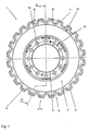
- FIG. 1 shows a coupling 1 according to the invention with a metallic hub 2 and a radially outer adjoining this hub elastic outer ring 3 made of silicone.
- the outer ring 3 has on its outer diameter 4 an outer contour 5, via which it transmits the introduced via the hub 2 torque to subsequent machine elements.
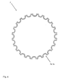
- a ring-shaped, rigid solid body 7 of aluminum strip of uniform thickness is embedded in the silicone material of the outer ring 3.
- the annular rigid solid body 7, as the outer contour 5 of the outer ring 3 semi-circular recesses 8, or recesses.
- the annular, rigid solid body 7 is completely surrounded by the silicone material, so that a uniformly thick layer 9 silicone material results around the annular, rigid solid 7 radially outward.
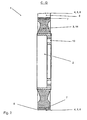
- the cross section 14 of the outer ring 3 tapers with increasing diameter.
- the cross section 14 expands again such that the annular, rigid solid body 7 is completely surrounded by the silicone material of the outer ring.
Landscapes
- Engineering & Computer Science (AREA)
- General Engineering & Computer Science (AREA)
- Mechanical Engineering (AREA)
- Mechanical Operated Clutches (AREA)
- Pulleys (AREA)
- Control Of Motors That Do Not Use Commutators (AREA)
- Snaps, Bayonet Connections, Set Pins, And Snap Rings (AREA)
- Braking Arrangements (AREA)
- Laminated Bodies (AREA)
Description
- Die Erfindung betrifft eine rotationssymmetrische Kupplung mit einer ringförmigen Nabe, die aus einem im wesentlichen starren Werkstoff besteht und von einem Außenring aus gummielastischem Werkstoff umgeben ist, sowie mit einer am Außendurchmesser angeordneten Außenkonturierung, über welche formschlüssig Drehmomente übertragen werden, wobei in dem Außenring nahe der Außenkonturierung ein im wesentlichen ringförmiger, starrer Festkörper in den gummielastischen Werkstoff des Außenringes eingebettet ist, welcher ebenfalls eine Außenkonturierung aufweist, wobei einzelne Ausformungen der Außenkonturierung des ringförmigen, starren Festkörpers in einzelne Ausformungen der Außenkonturierung des Außenringes radial von innen nach außen hineinragen und der ringförmige, starre Festkörper in seiner radial nach außen weisenden Form der Außenkonturierung des Außenrings ähnlich ist und über den Umfang einen nahezu konstanten Abstand zur Außenkonturierung des Außenrings aufweist.
- Bei einer nach dem Stande der Technik (
GB 2 101 709 A Figuren 1 bis 4 ) bekannten Kupplung besteht der eingebettete Festkörper aus einem starren, metallischen Ring, auf den jeweils dort, wo der Außenring aus gummielastischem Material einen radialen Vorsprung hat, ebenfalls ein radialer Vorsprung aufgeschweißt ist. Dabei ist die den metallischen Ring überdeckende Schicht aus gummielastischem Material jeweils im Bereich der Vorsprünge und jeweils in der Mitte zwischen zwei Vorsprüngen sehr dünn und im übrigen sehr dick. Das hat zur Folge, daß die elastischen Eigenschaften an den jeweiligen Lasteinleitpunkten am Umfang des Außenringes sehr ungleichmäßig sind, was zu einem unruhigen Lauf der Kupplung und zu einer Beschädigung der Außenkonturierung führen kann. Solche Beschädigungen sind insbesondere dann kritisch, wenn es aufgrund dieser Beschädigungen zu einem direkten Kontakt zwischen dem eingebetteten Festkörper und nachgeschalteten Maschinenelementen oder mit aggressiven Medien kommt. - Aus der
GB 2 101 709 A Figuren 5 und 6 ist eine Kupplung der eingangs genannten Art bekannt, bei der zwei ringförmige, starre Festkörper parallel nebeneinander in den gummielastischen Werkstoff des Außenrings eingebettet sind. Diese starren Festkörper sind verhältnismäßig schmal und stützen dementsprechend mit ihren radial nach außen weisenden Ausformungen die einzelnen Ausformungen des Außenrings in entsprechend schmalen Abstützbereichen ab, so daß auch hier örtliche Überbelastungen und Beschädigungen des elastischen Außenrings zu befürchten sind, die zu einem unruhigen Lauf der Kupplung führen. - Weiterhin ist aus der
DE 196 19 434 A1 eine Wellenkupplung mit einer äußeren und einer dazu koaxialen inneren Hülse bekannt, wobei der Spalt zwischen beiden Hülsen durch ein Elastomer gefüllt ist. Dabei hat die starre Außenhülse eine Außenkonturierung, über welche formschlüssig Drehmomente übertragen werden können. - Schließlich ist aus der
US 1 906 057 eine elastische Kupplung zur Übertragung von Drehmomenten bekannt, mit einer im Querschnitt dreieckigen Außenhülse, in welcher ein im Querschnitt ebenfalls dreieckiger Innenkörper angeordnet ist, wobei der Spalt zwischen der Außenhülse und dem Innenkörper durch eine gummielastische Masse gefüllt ist. - Es ist Aufgabe der Erfindung, die Kupplung der eingangs genannten Art daringehend weiterzubilden, daß sie ruhiger läuft und besser gegen Beschädigungen geschützt ist.
- Zur Lösung dieser Aufgabe sieht die Erfindung ausgehend von einer Kupplung der eingangs genannten Art vor, daß der gummielastische Werkstoff Silikon ist und daß der ringförmige, starre Festkörper aus gebogenem, metallischem Bandmaterial konstanter Dicke besteht und mit halbkreisförmigen Einformungen versehen ist.
- Durch die Verwendung von Silikonmaterial am Außenumfang verringert sich die Wahrscheinlichkeit der Beschädigung des Außenrings durch chemisch aggressive Medien. Die besondere Ausgestaltung des ringförmigen Festkörpers aus gebogenem, metallischen Bandmaterial mit halbkreisförmigen Einformungen macht es möglich, durch die Wahl der Stärke des Bandmaterials die Steifigkeit des verstärkenden Festkörpers den Erfordernissen anzupassen. Auf diese Weise wird eine optimale Dimensionierung des starren, ringförmigen Festkörpers unter Berücksichtigung erträglicher Steifigkeitssprünge möglich.
- Weiterhin ist vorgesehen, daß der ringförmige, starre Festkörper aus Aluminium oder einer Aluminiumlegierung besteht. Aluminium-Bandmaterial läßt sich besonders einfach zu dem erfingdungsgemäß verwendeten starren Ring verarbeiten, hat ein niedriges spezifisches Gewicht und verbindet sich hervorragend mit dem angrenzenden Silikonwerkstoff.
- Schließlich ist vorgesehen, daß der starre Festkörper vollständig von einer Schicht Silikonwerkstoff umgeben ist. Durch eine vollständige Einbettung des starren Festkörpers wird ein besonders guter Halt des Festkörpers sichergestellt. Außerdem ist der starre metallische Festkörper ringsum gut gegen den Zutritt von aggressiven Medien geschützt.
- Im folgenden wird die Erfindung anhand eines speziellen Ausführungsbeispieles unter Bezugnahme auf verschiedene Zeichnungen näher erläutert.
- Es zeigen:
- Fig. 1:
- Eine Seitenansicht einer erfindungsgemäßen Kupplung,
- Fig. 2:
- einen Schnitt durch eine erfindungsgemäße Kupplung gemäß dem Schnitt C-D aus
Figur 1 , - Fig. 3:
- einen Schnitt durch eine erfindungsgemäße Kupplung gemäß dem in der
Figur 1 dargestellten Schnitt A-B, - Fig. 4:
- einen erfindungsgemäßen ringförmigen, starren Festkörper,
- Fig. 5:
- einen Schnitt durch den erfindungsgemäßen starren Festkörper der
Figur 4 gemäß dem in derFigur 4 dargestellten Schnitt E-F. - Die
Figur 1 zeigt eine erfindungsgemäße Kupplung 1 mit einer metallischen Nabe 2 und einem radial außen an dieser Nabe anschließenden elastischen Außenring 3 aus Silikon. Der Außenring 3 besitzt auf seinem Außendurchmesser 4 eine Außenkonturierung 5, über welche er das über die Nabe 2 eingeleitete Drehmoment an nachfolgende Maschinenelemente überträgt. - Zur Unterstützung der einzelnen Ausformungen 6 der Außenkonturierung 5 des Außenrings 3 ist in den Silikonwerkstoff des Außenrings 3 ein ringförmiger, starrer Festkörper 7 aus Aluminiumband gleichmäßiger Dicke eingebettet. Der ringförmige starre Festkörper 7 weist, wie die Außenkonturierung 5 des Außenrings 3 halbkreisförmige Ausnehmungen 8, bzw. Einformungen auf. Der ringförmige, starre Festkörper 7 ist vollständig von dem Silikonwerkstoff umgeben, so daß sich radial nach außen eine gleichmäßig dicke Schicht 9 Silikonwerkstoff um den ringförmigen, starren Festkörper 7 ergibt.
- Die Krafteinleitung von der nicht dargestellten Welle auf die Nabe 2 erfolgt über Axialbohrungen 10. Zentrierbohrungen gewährleisten eine definierte Lage der Kupplung 1 zu der nicht dargestellten Welle. Auf der Nabe 2 und auf dem Außenring 3 sind jeweils eine Markierung 12 und 13 vorgesehen, welche eine plastische Verformung des Außenrings 3 durch einen Umfangsversatz der Markierungen 12, 13 erkennen lassen.
- Entsprechend der mit zunehmendem Radius abnehmenden spezifischen Belastung des Außenrings 3 verjüngt sich der Querschnitt 14 des Außenrings 3 mit zunehmendem Durchmesser. Zur Aufnahme des ringförmigen, starren Festkörpers 7 weitet sich der Querschnitt 14 derart wieder auf, daß der ringförmige, starre Festkörper 7 vollständig vom Silikonwerkstoff des Außenrings umgeben ist.
Claims (3)
- Rotationssymmetrische Kupplung (1) mit einer ringförmigen Nabe (2), die aus einem im wesentlichen starren Werkstoff besteht und von einem Außenring (3) aus gummielastischem Werkstoff umgeben ist, sowie mit einer am Außendurchmesser (4) angeordneten Außenkonturierung (5), über welche formschlüssig Drehmomente übertragen werden, wobei in dem Außenring (3) nahe der Außenkonturierung (5) ein im wesentlichen ringförmiger, starrer Festkörper (7) in den gummielastischen Werkstoff des Außenringes (3) eingebettet ist, welcher ebenfalls eine Außenkonturierung (7a) aufweist, wobei einzelne Ausformungen (7b) der Außenkonturierung (7a) des ringförmigen, starren Festkörpers (7) in einzelne Ausformungen der Außenkonturierung (5) des Außenringes (3) radial von innen nach außen hineinragen, und der ringförmige, starre Festkörper (7) in seiner radial nach außen weisenden Form der Außenkonturierung (5) des Außenrings (3) ähnlich ist und über den Umfang einen nahezu konstanten Abstand zur Außenkonturierung (5) des Außenringes (3) aufweist,
dadurch gekennzeichnet,
daß der gummielastische Werkstoff Silikon ist und daß der ringförmige, starre Festkörper (7) aus gebogenem, metallischem Bandmaterial konstanter Dicke besteht und mit halbkreisförmigen Einformungen versehen ist. - Kupplung nach Anspruch 1, dadurch gekennzeichnet, daß der ringförmige, starre Festkörper (7) aus Aluminium oder einer Aluminiumlegierung besteht.
- Kupplung nach Anspruch 1, dadurch gekennzeichnet, daß der ringförmige, starre Festkörper (7) vollständig von einer Schicht aus Silikonwerkstoff umgeben ist.
Priority Applications (1)
| Application Number | Priority Date | Filing Date | Title |
|---|---|---|---|
| CY20081100828T CY1110673T1 (el) | 2000-11-03 | 2008-08-06 | Διαταξη συζευξεως |
Applications Claiming Priority (3)
| Application Number | Priority Date | Filing Date | Title |
|---|---|---|---|
| DE20018823U | 2000-11-03 | ||
| DE20018823U DE20018823U1 (de) | 2000-11-03 | 2000-11-03 | Kupplung |
| PCT/EP2001/012738 WO2002044577A1 (de) | 2000-11-03 | 2001-11-02 | Kupplung |
Publications (2)
| Publication Number | Publication Date |
|---|---|
| EP1330613A1 EP1330613A1 (de) | 2003-07-30 |
| EP1330613B1 true EP1330613B1 (de) | 2008-05-07 |
Family
ID=7948452
Family Applications (1)
| Application Number | Title | Priority Date | Filing Date |
|---|---|---|---|
| EP01990386A Expired - Lifetime EP1330613B1 (de) | 2000-11-03 | 2001-11-02 | Kupplung |
Country Status (11)
| Country | Link |
|---|---|
| US (1) | US6976921B2 (de) |
| EP (1) | EP1330613B1 (de) |
| JP (1) | JP2004514857A (de) |
| AT (1) | ATE394607T1 (de) |
| AU (1) | AU2002229531A1 (de) |
| CY (1) | CY1110673T1 (de) |
| DE (2) | DE20018823U1 (de) |
| DK (1) | DK1330613T3 (de) |
| ES (1) | ES2307668T3 (de) |
| PT (1) | PT1330613E (de) |
| WO (1) | WO2002044577A1 (de) |
Cited By (2)
| Publication number | Priority date | Publication date | Assignee | Title |
|---|---|---|---|---|
| WO2010083938A1 (de) | 2009-01-26 | 2010-07-29 | Hackforth Gmbh | Elatische kupplung |
| CN101893081A (zh) * | 2010-07-23 | 2010-11-24 | 重庆隆鑫机车有限公司 | 发动机平衡轴从动齿轮 |
Families Citing this family (8)
| Publication number | Priority date | Publication date | Assignee | Title |
|---|---|---|---|---|
| US10989293B2 (en) * | 2016-06-09 | 2021-04-27 | Contitech Antriebssysteme Gmbh | Non-metal sprocket and bushing apparatus |
| US11015694B2 (en) * | 2016-06-09 | 2021-05-25 | Contitech Antriebssysteme Gmbh | Bushing and hub to prevent back-rotation |
| US10865868B2 (en) * | 2016-06-09 | 2020-12-15 | Contitech Antriebssysteme Gmbh | Non-metal sprocket |
| US11098797B2 (en) * | 2018-11-07 | 2021-08-24 | Contitech Antriebssysteme Gmbh | Synchronous sprocket profile for non-metal sprockets |
| JP7339076B2 (ja) * | 2019-08-30 | 2023-09-05 | ファナック株式会社 | 軽量歯車とその製造方法、歯車列の製造方法およびロボット |
| US11585423B2 (en) | 2020-10-03 | 2023-02-21 | Contitech Antriebssysteme Gmbh | Composite sprocket |
| DE102021108904A1 (de) | 2021-04-09 | 2022-10-13 | KTR Systems GmbH | Vorrichtung zur Übertragung von Drehmomenten |
| CN116677720A (zh) * | 2023-06-12 | 2023-09-01 | 无锡伏尔康科技有限公司 | 一种采用内嵌式铝齿圈结构的硅胶联轴器及制备工艺 |
Family Cites Families (14)
| Publication number | Priority date | Publication date | Assignee | Title |
|---|---|---|---|---|
| US1435141A (en) * | 1921-02-18 | 1922-11-07 | Smith | Flexible coupling device |
| US1906057A (en) * | 1929-09-13 | 1933-04-25 | Guy Murton Inc | Universal joint |
| GB897771A (en) * | 1958-07-25 | 1962-05-30 | William Cull | Resilient torque transmitting couplings and methods for their manufacture |
| US3272027A (en) * | 1964-11-18 | 1966-09-13 | Link Belt Co | Integral gear and drive eccentric unit |
| US3469467A (en) * | 1967-10-30 | 1969-09-30 | Borg Warner | Composite drive wheel |
| US3469468A (en) * | 1967-10-30 | 1969-09-30 | Borg Warner | Composite drive wheel |
| US3733921A (en) * | 1971-10-15 | 1973-05-22 | W Carveth | Reinforced plastic gear |
| US3730009A (en) * | 1971-12-15 | 1973-05-01 | Borg Warner | Composite drive wheel |
| DE2834490A1 (de) | 1978-08-07 | 1980-02-14 | Continental Gummi Werke Ag | Kupplung zum elastisch-beweglichen verbinden gleichachsiger wellen |
| DE3126644A1 (de) | 1981-07-07 | 1983-01-20 | Maschinenfabrik Stromag Gmbh, 4750 Unna | Drehelastische kupplung |
| US4722722A (en) * | 1986-06-27 | 1988-02-02 | Jepmar Research | Rotatable drive member formed from injection molded plastics material with preform insert |
| US5098346A (en) * | 1990-04-13 | 1992-03-24 | The Gates Rubber Company | Sprocket |
| JP3476164B2 (ja) | 1995-04-18 | 2003-12-10 | 株式会社豊田自動織機 | 圧縮機における動力伝達構造 |
| DE19619434B4 (de) | 1996-05-14 | 2004-04-15 | Wilhelm Kächele GmbH, Kautschuk- und Kunststoffwarenfabrik | Wellenkupplung |
-
2000
- 2000-11-03 DE DE20018823U patent/DE20018823U1/de not_active Expired - Lifetime
-
2001
- 2001-11-02 JP JP2002546087A patent/JP2004514857A/ja not_active Withdrawn
- 2001-11-02 AT AT01990386T patent/ATE394607T1/de active
- 2001-11-02 AU AU2002229531A patent/AU2002229531A1/en not_active Abandoned
- 2001-11-02 PT PT01990386T patent/PT1330613E/pt unknown
- 2001-11-02 EP EP01990386A patent/EP1330613B1/de not_active Expired - Lifetime
- 2001-11-02 DE DE50113949T patent/DE50113949D1/de not_active Expired - Lifetime
- 2001-11-02 ES ES01990386T patent/ES2307668T3/es not_active Expired - Lifetime
- 2001-11-02 DK DK01990386T patent/DK1330613T3/da active
- 2001-11-02 US US10/415,859 patent/US6976921B2/en not_active Expired - Lifetime
- 2001-11-02 WO PCT/EP2001/012738 patent/WO2002044577A1/de not_active Ceased
-
2008
- 2008-08-06 CY CY20081100828T patent/CY1110673T1/el unknown
Cited By (3)
| Publication number | Priority date | Publication date | Assignee | Title |
|---|---|---|---|---|
| WO2010083938A1 (de) | 2009-01-26 | 2010-07-29 | Hackforth Gmbh | Elatische kupplung |
| DE102009006104A1 (de) | 2009-01-26 | 2010-07-29 | Hackforth Gmbh | Elastische Kupplung |
| CN101893081A (zh) * | 2010-07-23 | 2010-11-24 | 重庆隆鑫机车有限公司 | 发动机平衡轴从动齿轮 |
Also Published As
| Publication number | Publication date |
|---|---|
| DE50113949D1 (de) | 2008-06-19 |
| US20040050199A1 (en) | 2004-03-18 |
| AU2002229531A1 (en) | 2002-06-11 |
| US6976921B2 (en) | 2005-12-20 |
| EP1330613A1 (de) | 2003-07-30 |
| ATE394607T1 (de) | 2008-05-15 |
| CY1110673T1 (el) | 2015-06-10 |
| DK1330613T3 (da) | 2008-09-15 |
| PT1330613E (pt) | 2008-08-08 |
| WO2002044577A1 (de) | 2002-06-06 |
| ES2307668T3 (es) | 2008-12-01 |
| DE20018823U1 (de) | 2001-01-18 |
| JP2004514857A (ja) | 2004-05-20 |
Similar Documents
| Publication | Publication Date | Title |
|---|---|---|
| EP1609996B1 (de) | Laufrad, insbesondere für einen Axialventilator | |
| DE1212108B (de) | Einkraenziges Axial-Stroemungsmaschinen-Laufrad | |
| DE102016202412A1 (de) | Dichtungsanordnung für Wälzlager, insbesondere für eine Nabenlagereinheit von Fahrzeugen und zugehörige Nabenlagereinheit | |
| DE10127224A1 (de) | Zahnrad | |
| EP1445507A1 (de) | Innenbelüftete Bremsscheibe mit gekrümmten Kühlluftkanälen | |
| WO2011103965A1 (de) | Verbindungsvorrichtung zum verbinden eines flexiblen gebindes mit einem flansch oder einem anschlussring | |
| EP2986872B1 (de) | Dichtungsmanschette für eine drehgelenkkupplung | |
| EP1330613A1 (de) | Kupplung | |
| DE102010027762A1 (de) | Einsatzstück für eine Strömungsmaschine und damit ausgerüstete Strömungsmaschine | |
| DE4409254B4 (de) | Torsionsschwingungsdämpfer | |
| DE10313162B4 (de) | Dichtring | |
| EP2692542A1 (de) | Reifen-Zierring | |
| DE102009048733A1 (de) | Spiralfeder für mechanische Schwingungssysteme von Uhren | |
| EP1121539B1 (de) | Elastische wellenkupplung mit torsionselement | |
| DE102008051242A1 (de) | Polrad und Montageverfahren hierfür | |
| EP1323958A1 (de) | Dichtring | |
| DE102022113154B4 (de) | Elastomerlager mit Schutzkappe | |
| DE19543516A1 (de) | Transportelement für flächiges Gut | |
| DE10127946B4 (de) | Radlagerung für Antriebsachsen | |
| EP2466148B1 (de) | Dichtungsanordnung für Kreiselpumpen | |
| DE1995812U (de) | Achslagerdichtung. | |
| DE102016122321B4 (de) | Bremsscheibe | |
| DE202018004820U1 (de) | Drehkolbenpumpe mit Verschleißelementen zur Förderung von mit Feststoffen durchsetzten Fördermedien | |
| EP0803456A1 (de) | Rohrbogen | |
| DE3629513A1 (de) | Bremskolben fuer eine scheibenbremse, insbesondere fuer kraftfahrzeuge |
Legal Events
| Date | Code | Title | Description |
|---|---|---|---|
| PUAI | Public reference made under article 153(3) epc to a published international application that has entered the european phase |
Free format text: ORIGINAL CODE: 0009012 |
|
| 17P | Request for examination filed |
Effective date: 20030503 |
|
| AK | Designated contracting states |
Designated state(s): AT BE CH CY DE DK ES FI FR GB GR IE IT LI LU MC NL PT SE TR |
|
| AX | Request for extension of the european patent |
Extension state: AL LT LV MK RO SI |
|
| 17Q | First examination report despatched |
Effective date: 20070503 |
|
| GRAP | Despatch of communication of intention to grant a patent |
Free format text: ORIGINAL CODE: EPIDOSNIGR1 |
|
| GRAS | Grant fee paid |
Free format text: ORIGINAL CODE: EPIDOSNIGR3 |
|
| GRAA | (expected) grant |
Free format text: ORIGINAL CODE: 0009210 |
|
| AK | Designated contracting states |
Kind code of ref document: B1 Designated state(s): AT BE CH CY DE DK ES FI FR GB GR IE IT LI LU MC NL PT SE TR |
|
| REG | Reference to a national code |
Ref country code: GB Ref legal event code: FG4D Free format text: NOT ENGLISH |
|
| REG | Reference to a national code |
Ref country code: CH Ref legal event code: EP |
|
| REG | Reference to a national code |
Ref country code: IE Ref legal event code: FG4D Free format text: LANGUAGE OF EP DOCUMENT: GERMAN |
|
| REF | Corresponds to: |
Ref document number: 50113949 Country of ref document: DE Date of ref document: 20080619 Kind code of ref document: P |
|
| REG | Reference to a national code |
Ref country code: PT Ref legal event code: SC4A Free format text: AVAILABILITY OF NATIONAL TRANSLATION Effective date: 20080729 |
|
| REG | Reference to a national code |
Ref country code: SE Ref legal event code: TRGR |
|
| REG | Reference to a national code |
Ref country code: DK Ref legal event code: T3 |
|
| REG | Reference to a national code |
Ref country code: GR Ref legal event code: EP Ref document number: 20080402171 Country of ref document: GR |
|
| REG | Reference to a national code |
Ref country code: CH Ref legal event code: NV Representative=s name: LUCHS & PARTNER PATENTANWAELTE |
|
| REG | Reference to a national code |
Ref country code: ES Ref legal event code: FG2A Ref document number: 2307668 Country of ref document: ES Kind code of ref document: T3 |
|
| PLBE | No opposition filed within time limit |
Free format text: ORIGINAL CODE: 0009261 |
|
| STAA | Information on the status of an ep patent application or granted ep patent |
Free format text: STATUS: NO OPPOSITION FILED WITHIN TIME LIMIT |
|
| 26N | No opposition filed |
Effective date: 20090210 |
|
| PG25 | Lapsed in a contracting state [announced via postgrant information from national office to epo] |
Ref country code: CY Free format text: LAPSE BECAUSE OF NON-PAYMENT OF DUE FEES Effective date: 20091102 |
|
| PGFP | Annual fee paid to national office [announced via postgrant information from national office to epo] |
Ref country code: TR Payment date: 20131128 Year of fee payment: 13 |
|
| PGFP | Annual fee paid to national office [announced via postgrant information from national office to epo] |
Ref country code: DK Payment date: 20141128 Year of fee payment: 14 |
|
| PGFP | Annual fee paid to national office [announced via postgrant information from national office to epo] |
Ref country code: IE Payment date: 20141128 Year of fee payment: 14 Ref country code: MC Payment date: 20141212 Year of fee payment: 14 Ref country code: LU Payment date: 20141201 Year of fee payment: 14 Ref country code: GR Payment date: 20141125 Year of fee payment: 14 Ref country code: CH Payment date: 20141219 Year of fee payment: 14 |
|
| PGFP | Annual fee paid to national office [announced via postgrant information from national office to epo] |
Ref country code: PT Payment date: 20141211 Year of fee payment: 14 |
|
| PGFP | Annual fee paid to national office [announced via postgrant information from national office to epo] |
Ref country code: BE Payment date: 20141128 Year of fee payment: 14 |
|
| PGFP | Annual fee paid to national office [announced via postgrant information from national office to epo] |
Ref country code: CY Payment date: 20141215 Year of fee payment: 14 |
|
| REG | Reference to a national code |
Ref country code: FR Ref legal event code: PLFP Year of fee payment: 15 |
|
| REG | Reference to a national code |
Ref country code: PT Ref legal event code: MM4A Free format text: LAPSE DUE TO NON-PAYMENT OF FEES Effective date: 20160502 |
|
| REG | Reference to a national code |
Ref country code: DK Ref legal event code: EBP Effective date: 20151130 |
|
| PG25 | Lapsed in a contracting state [announced via postgrant information from national office to epo] |
Ref country code: MC Free format text: LAPSE BECAUSE OF NON-PAYMENT OF DUE FEES Effective date: 20151130 Ref country code: LU Free format text: LAPSE BECAUSE OF NON-PAYMENT OF DUE FEES Effective date: 20151102 |
|
| REG | Reference to a national code |
Ref country code: CH Ref legal event code: PL |
|
| PG25 | Lapsed in a contracting state [announced via postgrant information from national office to epo] |
Ref country code: GR Free format text: LAPSE BECAUSE OF NON-PAYMENT OF DUE FEES Effective date: 20160602 Ref country code: CH Free format text: LAPSE BECAUSE OF NON-PAYMENT OF DUE FEES Effective date: 20151130 Ref country code: CY Free format text: LAPSE BECAUSE OF NON-PAYMENT OF DUE FEES Effective date: 20151102 Ref country code: LI Free format text: LAPSE BECAUSE OF NON-PAYMENT OF DUE FEES Effective date: 20151130 |
|
| REG | Reference to a national code |
Ref country code: IE Ref legal event code: MM4A |
|
| PG25 | Lapsed in a contracting state [announced via postgrant information from national office to epo] |
Ref country code: PT Free format text: LAPSE BECAUSE OF NON-PAYMENT OF DUE FEES Effective date: 20160502 |
|
| REG | Reference to a national code |
Ref country code: GR Ref legal event code: ML Ref document number: 20080402171 Country of ref document: GR Effective date: 20160602 |
|
| PG25 | Lapsed in a contracting state [announced via postgrant information from national office to epo] |
Ref country code: IE Free format text: LAPSE BECAUSE OF NON-PAYMENT OF DUE FEES Effective date: 20151102 Ref country code: DK Free format text: LAPSE BECAUSE OF NON-PAYMENT OF DUE FEES Effective date: 20151130 |
|
| REG | Reference to a national code |
Ref country code: FR Ref legal event code: PLFP Year of fee payment: 16 |
|
| PG25 | Lapsed in a contracting state [announced via postgrant information from national office to epo] |
Ref country code: BE Free format text: LAPSE BECAUSE OF NON-PAYMENT OF DUE FEES Effective date: 20151130 |
|
| PG25 | Lapsed in a contracting state [announced via postgrant information from national office to epo] |
Ref country code: TR Free format text: LAPSE BECAUSE OF NON-PAYMENT OF DUE FEES Effective date: 20151102 |
|
| REG | Reference to a national code |
Ref country code: FR Ref legal event code: PLFP Year of fee payment: 17 |
|
| PGFP | Annual fee paid to national office [announced via postgrant information from national office to epo] |
Ref country code: NL Payment date: 20201125 Year of fee payment: 20 |
|
| PGFP | Annual fee paid to national office [announced via postgrant information from national office to epo] |
Ref country code: AT Payment date: 20201119 Year of fee payment: 20 Ref country code: IT Payment date: 20201124 Year of fee payment: 20 Ref country code: FI Payment date: 20201119 Year of fee payment: 20 Ref country code: SE Payment date: 20201125 Year of fee payment: 20 Ref country code: FR Payment date: 20201120 Year of fee payment: 20 Ref country code: GB Payment date: 20201120 Year of fee payment: 20 Ref country code: DE Payment date: 20201119 Year of fee payment: 20 |
|
| PGFP | Annual fee paid to national office [announced via postgrant information from national office to epo] |
Ref country code: ES Payment date: 20210122 Year of fee payment: 20 |
|
| REG | Reference to a national code |
Ref country code: DE Ref legal event code: R071 Ref document number: 50113949 Country of ref document: DE |
|
| REG | Reference to a national code |
Ref country code: NL Ref legal event code: MK Effective date: 20211101 |
|
| REG | Reference to a national code |
Ref country code: GB Ref legal event code: PE20 Expiry date: 20211101 |
|
| REG | Reference to a national code |
Ref country code: FI Ref legal event code: MAE |
|
| REG | Reference to a national code |
Ref country code: AT Ref legal event code: MK07 Ref document number: 394607 Country of ref document: AT Kind code of ref document: T Effective date: 20211102 |
|
| REG | Reference to a national code |
Ref country code: SE Ref legal event code: EUG |
|
| PG25 | Lapsed in a contracting state [announced via postgrant information from national office to epo] |
Ref country code: GB Free format text: LAPSE BECAUSE OF EXPIRATION OF PROTECTION Effective date: 20211101 |
|
| REG | Reference to a national code |
Ref country code: ES Ref legal event code: FD2A Effective date: 20220225 |
|
| PG25 | Lapsed in a contracting state [announced via postgrant information from national office to epo] |
Ref country code: ES Free format text: LAPSE BECAUSE OF EXPIRATION OF PROTECTION Effective date: 20211103 |