EP1328765B1 - Pellet press for dry ice - Google Patents
Pellet press for dry ice Download PDFInfo
- Publication number
- EP1328765B1 EP1328765B1 EP01960192A EP01960192A EP1328765B1 EP 1328765 B1 EP1328765 B1 EP 1328765B1 EP 01960192 A EP01960192 A EP 01960192A EP 01960192 A EP01960192 A EP 01960192A EP 1328765 B1 EP1328765 B1 EP 1328765B1
- Authority
- EP
- European Patent Office
- Prior art keywords
- carbon dioxide
- dry ice
- gas
- pressing
- pressing chamber
- Prior art date
- Legal status (The legal status is an assumption and is not a legal conclusion. Google has not performed a legal analysis and makes no representation as to the accuracy of the status listed.)
- Expired - Lifetime
Links
- CURLTUGMZLYLDI-UHFFFAOYSA-N Carbon dioxide Chemical compound O=C=O CURLTUGMZLYLDI-UHFFFAOYSA-N 0.000 title claims abstract description 228
- 235000011089 carbon dioxide Nutrition 0.000 title claims abstract description 74
- 239000008188 pellet Substances 0.000 title claims abstract description 59
- 239000001569 carbon dioxide Substances 0.000 claims abstract description 77
- 229910002092 carbon dioxide Inorganic materials 0.000 claims abstract description 77
- 238000003825 pressing Methods 0.000 claims abstract description 63
- 239000012530 fluid Substances 0.000 claims abstract description 21
- 238000005422 blasting Methods 0.000 claims abstract description 15
- 239000007787 solid Substances 0.000 claims abstract description 6
- 239000007789 gas Substances 0.000 claims description 44
- 238000011084 recovery Methods 0.000 claims description 28
- 238000005520 cutting process Methods 0.000 claims description 17
- 239000007788 liquid Substances 0.000 claims description 10
- 230000006835 compression Effects 0.000 claims description 6
- 238000007906 compression Methods 0.000 claims description 6
- 239000012159 carrier gas Substances 0.000 claims description 3
- 238000007599 discharging Methods 0.000 claims description 2
- 238000010438 heat treatment Methods 0.000 claims description 2
- 238000003860 storage Methods 0.000 claims description 2
- 230000001131 transforming effect Effects 0.000 claims 1
- 238000010276 construction Methods 0.000 abstract description 4
- 238000004519 manufacturing process Methods 0.000 description 30
- 238000001816 cooling Methods 0.000 description 11
- 239000000463 material Substances 0.000 description 8
- 239000002826 coolant Substances 0.000 description 4
- 238000009825 accumulation Methods 0.000 description 3
- 238000010586 diagram Methods 0.000 description 3
- 238000009834 vaporization Methods 0.000 description 3
- 238000001125 extrusion Methods 0.000 description 2
- 238000000034 method Methods 0.000 description 2
- 239000002699 waste material Substances 0.000 description 2
- 230000015572 biosynthetic process Effects 0.000 description 1
- 238000004140 cleaning Methods 0.000 description 1
- 239000011248 coating agent Substances 0.000 description 1
- 238000000576 coating method Methods 0.000 description 1
- 150000001875 compounds Chemical class 0.000 description 1
- 238000011109 contamination Methods 0.000 description 1
- 238000011038 discontinuous diafiltration by volume reduction Methods 0.000 description 1
- 238000005516 engineering process Methods 0.000 description 1
- 238000007710 freezing Methods 0.000 description 1
- 230000008014 freezing Effects 0.000 description 1
- 238000002347 injection Methods 0.000 description 1
- 239000007924 injection Substances 0.000 description 1
- 238000009413 insulation Methods 0.000 description 1
- 239000003973 paint Substances 0.000 description 1
- 239000002245 particle Substances 0.000 description 1
- 231100000614 poison Toxicity 0.000 description 1
- 230000007096 poisonous effect Effects 0.000 description 1
- 238000002360 preparation method Methods 0.000 description 1
- 238000000926 separation method Methods 0.000 description 1
- 239000000243 solution Substances 0.000 description 1
- 239000000126 substance Substances 0.000 description 1
- 238000010257 thawing Methods 0.000 description 1
- XLYOFNOQVPJJNP-UHFFFAOYSA-N water Substances O XLYOFNOQVPJJNP-UHFFFAOYSA-N 0.000 description 1
Images




Classifications
-
- F—MECHANICAL ENGINEERING; LIGHTING; HEATING; WEAPONS; BLASTING
- F17—STORING OR DISTRIBUTING GASES OR LIQUIDS
- F17C—VESSELS FOR CONTAINING OR STORING COMPRESSED, LIQUEFIED OR SOLIDIFIED GASES; FIXED-CAPACITY GAS-HOLDERS; FILLING VESSELS WITH, OR DISCHARGING FROM VESSELS, COMPRESSED, LIQUEFIED, OR SOLIDIFIED GASES
- F17C7/00—Methods or apparatus for discharging liquefied, solidified, or compressed gases from pressure vessels, not covered by another subclass
- F17C7/02—Discharging liquefied gases
- F17C7/04—Discharging liquefied gases with change of state, e.g. vaporisation
-
- F—MECHANICAL ENGINEERING; LIGHTING; HEATING; WEAPONS; BLASTING
- F17—STORING OR DISTRIBUTING GASES OR LIQUIDS
- F17C—VESSELS FOR CONTAINING OR STORING COMPRESSED, LIQUEFIED OR SOLIDIFIED GASES; FIXED-CAPACITY GAS-HOLDERS; FILLING VESSELS WITH, OR DISCHARGING FROM VESSELS, COMPRESSED, LIQUEFIED, OR SOLIDIFIED GASES
- F17C7/00—Methods or apparatus for discharging liquefied, solidified, or compressed gases from pressure vessels, not covered by another subclass
-
- C—CHEMISTRY; METALLURGY
- C01—INORGANIC CHEMISTRY
- C01B—NON-METALLIC ELEMENTS; COMPOUNDS THEREOF; METALLOIDS OR COMPOUNDS THEREOF NOT COVERED BY SUBCLASS C01C
- C01B32/00—Carbon; Compounds thereof
- C01B32/50—Carbon dioxide
- C01B32/55—Solidifying
Definitions
- the present invention concerns an apparatus for making dry ice pellets.
- the invention furthermore concerns a device for dry ice blasting, a mobile unit and use of such an apparatus.
- US patent 58445516 discloses a dry ice pelletizer and method for pellet production having multiple injection ports used for the timed introduction of liquid carbon dioxide into a dry ice extrusion cylinder so that the cylinder can be more completely filled with carbon dioxide snow before extrusion takes place.
- Ice of carbon dioxide also called dry ice
- Ice of carbon dioxide is used in connection with cooling of foodstuffs as the ice, when, thawing at room temperature, vaporises and does not leave any residues. Furthermore, the substance is not poisonous, which is an important feature.
- dry ice is dry ice blasting for cleaning surfaces. Dry ice pellets are accelerated and directed against the surface of an object for removing the coating of the surface, e.g. remains of paint or dirt.
- a second solution to the problem is to collect the produced pellets in containers which are transported to the dry ice blaster on the site of blasting. This transport, however, causes a great loss of pellets by vaporisation from the only partly insulated containers. Thus new dry ice pellets have to be transported daily to the blaster which is a great disadvantage.
- the purpose of the invention is to provide an apparatus for making dry ice pellets which does not have the above drawbacks and which is particularly suited for compact units, preferably mobile units.
- an apparatus for dry ice production which is far lighter and more compact that prior art units, and which in spite of its small size has a relatively high production capacity.
- inventive apparatus being provided with plural pressing chamber, even by far smaller pressing chambers there can be achieved a production of dry ice pellets in an amount comparable to the yield from far larger prior art units with one or two pressing chambers. Thereby is achieved an apparatus being far more compact and lighter that prior art units.
- the apparatus may be designed so that the capacity of dry ice pellet production is less than prior art units. As the production capacity compared to the size of the apparatus is far greater than by the known principles, an apparatus according to the invention is suitable for mobile units.
- the smaller pressing chambers in an apparatus according to the invention are to resist a pressure which is comparable to the pressure in larger pressing chambers in prior art units, but the sufficient wall thickness of the small chamber may be made less than the wall thickness in large chambers which saves material. As the piston area may also be less than the prior art apparatuses, the total force on the pistons is less, whereby less material is used for the pistons.
- an apparatus according to the invention may be made with pressing chambers having a cycle time of half a second. By six pressing chambers is thereby achieved a dry ice pellet production with a frequency of 12 Hz. As the production time for each pressing chamber during a cycle is approximately one sixth of this cycle, an almost continual pellet production is achieved without any interruption in the production as one pressing chamber begins to produce dry ice pellets before another chamber has finished its production.
- At least a part of the outer wall of the pressing chamber is enclosed with fluid carbon dioxide, as also the inner wall of the pressing chamber is thereby heated up in relation to the temperature of the carbon dioxide snow inside the pressing chamber. In this way, no carbon dioxide ice is formed on the inner wall of the pressing chamber, and the friction between the piston and the inner wall is reduced.
- This further development of the invention may also be used with advantage in apparatuses according to prior art but is particularly useful in connection with an apparatus according to the invention.
- the piston, the connecting rods and the crankshaft be dimensioned in a way which is far less material demanding than immediately expected with background in prior art. This material saving measure is particularly useful in application of an apparatus according to the invention in connection with a mobile unit.
- a cutting unit may be placed at each perforated plate, e.g. a propeller cutter as described in the above US 5 473 903 .
- Typical dry ice pellets are 1 to 4 mm in diameter and I to 10 mm in length. The invention, however, is not limited to these pellet sizes.
- Another cutting unit may be formed as a screw running across of the perforated plates.
- the perforated plates are designed with a concave outer side at which the screw is disposed.
- the same screw may be used for all the pressing chambers in the apparatus, contributing to making the apparatus according to the invention in very compact form, which generally is an advantage but particularly if the apparatus is used in conjunction with a mobile unit. If advantageous, it is within the frame of the invention to use several screws for transporting the dry ice pellets.
- a cutter unit with one or more cutter blade disposed in parallel with the axis of rotation can be used instead of a screw with helical cutting blade.
- Fig. 1a shows a pressing chamber 101 with side wall 102 and perforated plate 103.
- a piston 104 linearly movable in the pressing chamber 101, is reciprocated in the chamber by means of a connecting rod 105 which through a link 106 is connected with a connecting rod 107.
- the connecting rod 107 is in engagement with a rotating bearing 108 on the crankshaft 109.
- the pressing chamber 101 is furthermore provided with an inlet 110 and an inlet valve 111 for fluid carbon dioxide and a outlet 112 for carbon dioxide in gaseous state.
- Figs. 1a-1d illustrate the function of the pressing chamber 101.
- the perforated plate 103 is closed with dry ice 113 from the last production cycle. Due to the rotation of the crankshaft 109 in the direction indicated with arrow 114, the piston 104 is moved in direction away from the perforated plate 103 as indicated with a second arrow 115.
- liquid carbon dioxide 118 is supplied from the opened inlet valve 111 through the inlet 110 into the interior 116 of the pressing chamber 101, whereby carbon dioxide snow 117 and carbon dioxide gas 119 are formed due to pressure differences between the inlet 110 and the interior 116 of the pressing chamber.
- the gas 119 leaves the interior 116 via the outlet 112.
- a filter screen 120 at the outlet 112 retains the carbon dioxide snow 117 in the interior of the chamber 116.
- Fig. 1b On Fig. 1b the piston 104 has reached it first dead point, and the interior 116 of the chamber is filled with carbon dioxide snow. The valve 11 is subsequently closed as shown on Fig. 1c. During the continued rotation of the crankshaft 109, the snow 117 is compressed to a solid mass and is pressed through the apertures in the perforated plate 103 as shown on Fig. Id, where the piston 104 has reached its second dead point and commences the return stroke.
- Figs. 2a and 2b On Figs. 2a and 2b is seen the pressing chamber 101 in to different views together with the connecting rods 105 and 107 together with connecting rods 107', 107" and bearings 108',108" for the two other pressing chambers 101',101 ".
- the three pistons 104,104',104" shown have different mutual positions, and their cycles are mutually displaced with one third revolution of the crankshaft 109. For each revolution of the crankshaft 109, three portions of dry ice pellets will thus be produced.
- the number of pressing chambers has to be adapted to the production time of each pressing chamber within a cycle. If the production time is one sixth, or one eighth, respectively, of a cycle, there is need for six or eight, respectively, pressing chambers working angularly displaced with one sixth or one eighth, respectively, of a revolution of the crankshaft.
- the dry ice 113 leaves the perforated plate 103 as rods, where each rod has cross-section equal to the hole through which the rod is pressed through.
- a cutting unit cuts these rods into suitable lengths.
- the apparatus according to the invention may provide different pellet sizes and with different piston pressure.
- the inner diameter of the pressing chambers is between 10 and 80 mm, preferably between 15 and 30 mm, and most preferred between 18 and 25 mm.
- the stroke of the piston may e.g. be between 20 and 300 mm, preferably between 30 and 150 mm, and most preferred between 50 and 100 mm.
- the pressure of the piston on the solid carbon dioxide is e.g. between 20 and 1000 bar, preferably between 80 and 500 bar, and most preferred between 200 and 400 bar.
- the cycle time of a cycle of a pressing chamber with reciprocating piston is e.g. between 0.05 and 30 seconds, preferably between 0.2 and 5 seconds, and most preferred between 0.5 and 2 seconds.
- FIG. 2a On Fig. 2a is shown a second embodiment of an inlet valve 201.
- This inlet valve 201 is designed as a shutter 202 in a valve seat 203 which is mechanically connected with the wall of the pressing chamber, where the shutter 202 is surrounded by fluid carbon dioxide in a reservoir 204 at least partly surrounding the pressing chambers.
- the surrounding reservoir 204 of fluid carbon dioxide contains an amount of carbon dioxide which is relatively great compared with the amount currently used, whereby the pressure and temperature in this buffer will not change substantially. This implies that the pressure and the temperature in the valve 201 at the inlet 110 to the pressing chamber 101 is not changed substantially, and that the valve therefore does not freeze even if the valve is of a very simple construction.
- a cutter unit 301 is shown i three different views, where Fig. 3a shows the cutting unit as seen in direction perpendicular to the pressing chambers 101,101',101" and perpendicular to the axis of rotation 302 of the cutting unit 301.
- Fig. 3b shows the cutting unit 301 as seen in direction perpendicular to the pressing chambers and in parallel with the axis of rotation 302 of the cutting unit
- Fig. 3c shows the cutting unit 301 as seen in direction perpendicular to the outer side of the perforated plate, where, however, only half of the cutting unit is shown.
- the cutting unit 301 rotates about an axis 302 in a cylindrical housing 304 and has cutter blades 303 extending in parallel with the axis of rotation 302.
- the perforated plates are formed with a concave outer side 305 forming wall in the cylindric housing 304 in which the cutter unit 301 is running.
- the length of the cut dry ice pellets in front of the perforated plate 103 depend on the rotational speed of the cutting unit.
- the cut pellets may e.g. be conveyed from the perforated plate 103 to a collecting container or to the place of use by means of carrier gas which is blown past the outer side of the perforated plate 103.
- This carrier gas may be carbon dioxide from the outlet 112 but it is preferred to use other gas with higher pressure from recovery facilities as described below.
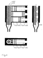
- the cutter unit is also possible to design the cutter unit as a screw 401 as illustrated on Fig. 4 in several views corresponding to Figs. 3a - 3c, respectively. Rotation of the screw 401 leads to cutting of the dry ice pellets and conveying along the axis of rotation 402 of the screw.
- Fig. 5 shows in principle the connection between the pressing chamber with a carbon dioxide recovery facility 600.
- Gas leaving the pressing chamber 101 via the outlet 112 has a temperature lower than the supplied fluid carbon dioxide. Therefore, it is known to use a heat exchanger 501 in which the heat from the fluid carbon dioxide in the inlet pipe 502 is transferred to the carbon dioxide gas in the outlet pipe 503 to achieve cooling of the fluid carbon dioxide for increasing the effectiveness of the dry ice press.
- the fluid carbon dioxide is primarily supplied from a carbon dioxide tank 504 provided with a shutoff valve 505.
- Carbon dioxide gas from vaporisation of fluid carbon dioxide in the supply pipes 502 is received in a first container 510.
- the container 510 contains liquid carbon dioxide as well as gas. When the liquid level in the container 510 drops, this is registered by a level sensor 507 causing a valve 508 to open for conduction of gas through a recovery pipe 509 to a recovery plant 600.
- the gas collected from the outlet 112 is also supplied to the recovery facility 600 through the outlet pipe 503. In the recovery facility 600, the gas is condensed to liquid carbon dioxide which then enters the circuit via the supply pipe 502.
- Fig. 6 shows the recovery facility 600 in greater detail in a first embodiment.
- the gas from the outlet 112 is supplied to a first compression stage 604 of which a gas container 601 forms a part, causing levelling of fluctuations in the gas flow before a compressor 602.
- a first compression stage 604 of which a gas container 601 forms a part, causing levelling of fluctuations in the gas flow before a compressor 602.
- an apparatus according to the invention may operate at a higher pressure in the outlet pipe 503 and a more even gas flow due to the higher frequency of the cycles. Not only a volume reduction is thereby attained in an apparatus according to the invention but it also provides possibility for using a compressor with relatively low yield and power consumption.
- the compressor 602 is driven by a motor 603 and compresses the gas whereby this achieves higher temperature and pressure. In a subsequent heat exchanger 605 heat is extracted from the gas. At the first compression stage 604, gas is supplied from the first container 510 through the recovery pipe 509.
- the carbon dioxide is subjected to a second compression stage 606 which corresponds to the first compression stage 604 and also comprising a gas container 601', a compressor 602' driven by a motor 603', and a heat exchanger 605'.
- a discharge valve 615 for discharging gas.
- the carbon dioxide gas is condensed to liquid state by further cooling in a heat exchanger 607 forming part of a cooling circuit with coolant, e.g. freon, compressor 608 driven by a motor 609, and a heat exchanger 610.
- coolant e.g. freon
- compressor 608 driven by a motor 609
- heat exchanger 610 In the circuit there is also an expansion valve 611 for the coolant.
- An arrangement with a container 612, a level sensor 613 and an automatic valve 614 ensures that only liquid carbon dioxide is conducted to the supply pipe 502. Gas from the container 612 is condensed in heat exchanger 607.
- Fig. 7 shows the recovery facility 600 in greater detail in a second embodiment.
- the three pressing chambers 101,101',101" are fed with fluid carbon dioxide through the inlet valves 111,111',111".
- the gas from the outlet 112 goes through a heat exchanger 501 for cooling the supplied fluid carbon dioxide from the supply pipe 502.
- the carbon dioxide is drawn from a tank 504 through a shutoff valve 505 as in the illustration on Fig. 5.
- Possible gas from the tank 504 and gas from the first container enter the recovery facility through pipe 616 and recovery pipe 509.
- the gas from the outlet 112 on Fig. 7 is provided with two compressing stages 604 and 606 where the gas from the recovery pipe 509 enters after container 601'.
- Compressor 602,602' is driven by motor 603,603' which is controlled via pressure sensors 707,707'.
- the carbon dioxide runs through a particle filter 702 for safeguarding the succeeding compressors.
- a recovery facility By an apparatus according to the invention utilised in a smaller scale, preferably as mobile unit, a recovery facility will need a capacity which is less than that being necessary in connection with many large existing units.
- the components in the recovery facility may therefore be selected among components which are used in other commercial and widely used cooling units.
- the widely used and cheap oil lubricated compressors may thus be utilised.
- an oil separation filter 703 forms a part of the recovery facility 600. Possible contamination, such as oil collected in this filter, may be taken out via the outlet 704 and possibly reused.
- the carbon dioxide runs through a third cooling compressing stage in which there is a cooling circuit with coolant, e.g. freon, compressor 608 driven by a motor 609, and a coolant condenser 610.
- coolant e.g. freon
- a part of the remaining gas after this stage is drawn off via an additional discharge pipe 705 for counteracting accumulation of other gasses as the carbon dioxide from the tank 504 possibly contains small amounts of other materials.
- the gas from discharge pipe 705 may be used for transporting the dry ice pellets through pipe 705' to the destination 706.
- gas from the outlet 112 for transporting the pellets if this gas is supplied to the discharge side of the perforated plates 103 by means of a pipe system.
- the discharge gas is preferred for transporting the dry ice pellets.
- the hot air produced in heat exchanger 605,605' and possibly 610 may advantageously be led to the destination 706 for heating the surface of the object to be treated, or which has be treated with dry ice blasting.
- Materials to be removed from a surface by dry ice blasting may often be heated with hot air with advantage before the treatment.
- An apparatus according to the invention including a recovery facility, has a volume which in principle is not limited to some fixed values and may be provided e.g. with a volume between 0.5 and 6 m 3 , preferably between 1 and 4 m 3 , and most preferred between 1 and 2 m 3 .
- the weight is e.g. between 100 and 2000 kg, preferably between 150 and 1200 kg, and most preferred between 200 and 750 kg.
- the invention has been illustrated with plural pressing chambers disposed in parallel. However, it is within the scope of the invention to configure the pressing chambers in other ways as also known from car or airplane engines, e.g. in V-form or radially.
Landscapes
- Engineering & Computer Science (AREA)
- Chemical & Material Sciences (AREA)
- Mechanical Engineering (AREA)
- General Engineering & Computer Science (AREA)
- Organic Chemistry (AREA)
- Inorganic Chemistry (AREA)
- Chemical Kinetics & Catalysis (AREA)
- Carbon And Carbon Compounds (AREA)
- Glanulating (AREA)
- Press Drives And Press Lines (AREA)
- Application Of Or Painting With Fluid Materials (AREA)
- Chair Legs, Seat Parts, And Backrests (AREA)
- Window Of Vehicle (AREA)
- Freezing, Cooling And Drying Of Foods (AREA)
Applications Claiming Priority (3)
| Application Number | Priority Date | Filing Date | Title |
|---|---|---|---|
| DKPA200001319 | 2000-09-05 | ||
| DK200001319 | 2000-09-05 | ||
| PCT/DK2001/000535 WO2002021059A1 (en) | 2000-09-05 | 2001-08-14 | Pellet press for dry ice |
Publications (2)
| Publication Number | Publication Date |
|---|---|
| EP1328765A1 EP1328765A1 (en) | 2003-07-23 |
| EP1328765B1 true EP1328765B1 (en) | 2008-01-09 |
Family
ID=8159695
Family Applications (1)
| Application Number | Title | Priority Date | Filing Date |
|---|---|---|---|
| EP01960192A Expired - Lifetime EP1328765B1 (en) | 2000-09-05 | 2001-08-14 | Pellet press for dry ice |
Country Status (11)
| Country | Link |
|---|---|
| US (1) | US6986265B2 (da) |
| EP (1) | EP1328765B1 (da) |
| JP (1) | JP2004508270A (da) |
| KR (1) | KR100829916B1 (da) |
| AT (1) | ATE383556T1 (da) |
| AU (1) | AU2001281748A1 (da) |
| CA (1) | CA2421261C (da) |
| DE (1) | DE60132346T2 (da) |
| DK (1) | DK1328765T3 (da) |
| ES (1) | ES2299503T3 (da) |
| WO (1) | WO2002021059A1 (da) |
Cited By (3)
| Publication number | Priority date | Publication date | Assignee | Title |
|---|---|---|---|---|
| DE102008027283A1 (de) | 2008-06-06 | 2009-12-10 | Linde Ag | Vorrichtung zur Erzeugung von Trockeneispellets und Verfahren zur Oberflächenreinigung |
| WO2021078891A1 (de) | 2019-10-25 | 2021-04-29 | Messer Group Gmbh | Vorrichtung und verfahren zum erzeugen und transportieren von trockeneispellets |
| EP3695160B1 (en) * | 2017-10-09 | 2023-07-19 | Cold Blasting APS | Dry ice pelletizer |
Families Citing this family (46)
| Publication number | Priority date | Publication date | Assignee | Title |
|---|---|---|---|---|
| GB2414067B (en) * | 2004-04-13 | 2006-12-06 | Triventek As | Carbon dioxide recovery |
| JP4815110B2 (ja) * | 2004-08-13 | 2011-11-16 | 株式会社シュトルツ | ドライアイスペレット製造方法及び装置 |
| DE102005035433A1 (de) * | 2005-07-28 | 2007-02-01 | Linde Ag | Vorrichtung und Verfahren zur Reinigung von Laufschienen |
| US20070178811A1 (en) * | 2006-02-01 | 2007-08-02 | Meenakshi Sundaram | Dry ice blasting with chemical additives |
| US20070261436A1 (en) * | 2006-02-03 | 2007-11-15 | Meenakshi Sundaram | Dry ice products and method of making same |
| DE102007014284B4 (de) * | 2007-03-19 | 2009-02-26 | Alfred Kärcher Gmbh & Co. Kg | Vorrichtung zum Zerkleinern von Trockeneisgranulat und Trockeneisabgabeanordnung mit einer derartigen Vorrichtung |
| US8725420B2 (en) | 2008-10-31 | 2014-05-13 | The Invention Science Fund I, Llc | Compositions and methods for surface abrasion with frozen particles |
| US9060926B2 (en) * | 2008-10-31 | 2015-06-23 | The Invention Science Fund I, Llc | Compositions and methods for therapeutic delivery with frozen particles |
| US8551505B2 (en) * | 2008-10-31 | 2013-10-08 | The Invention Science Fund I, Llc | Compositions and methods for therapeutic delivery with frozen particles |
| US9050317B2 (en) | 2008-10-31 | 2015-06-09 | The Invention Science Fund I, Llc | Compositions and methods for therapeutic delivery with frozen particles |
| US20100111834A1 (en) * | 2008-10-31 | 2010-05-06 | Searete Llc, A Limited Liability Corporation Of The State Of Delaware | Compositions and methods for therapeutic delivery with frozen particles |
| US20100111857A1 (en) | 2008-10-31 | 2010-05-06 | Boyden Edward S | Compositions and methods for surface abrasion with frozen particles |
| US9072688B2 (en) * | 2008-10-31 | 2015-07-07 | The Invention Science Fund I, Llc | Compositions and methods for therapeutic delivery with frozen particles |
| US9050070B2 (en) | 2008-10-31 | 2015-06-09 | The Invention Science Fund I, Llc | Compositions and methods for surface abrasion with frozen particles |
| US8731841B2 (en) * | 2008-10-31 | 2014-05-20 | The Invention Science Fund I, Llc | Compositions and methods for therapeutic delivery with frozen particles |
| US8409376B2 (en) | 2008-10-31 | 2013-04-02 | The Invention Science Fund I, Llc | Compositions and methods for surface abrasion with frozen particles |
| US8731840B2 (en) | 2008-10-31 | 2014-05-20 | The Invention Science Fund I, Llc | Compositions and methods for therapeutic delivery with frozen particles |
| US9060934B2 (en) | 2008-10-31 | 2015-06-23 | The Invention Science Fund I, Llc | Compositions and methods for surface abrasion with frozen particles |
| US8788211B2 (en) * | 2008-10-31 | 2014-07-22 | The Invention Science Fund I, Llc | Method and system for comparing tissue ablation or abrasion data to data related to administration of a frozen particle composition |
| US8793075B2 (en) * | 2008-10-31 | 2014-07-29 | The Invention Science Fund I, Llc | Compositions and methods for therapeutic delivery with frozen particles |
| US20100111831A1 (en) * | 2008-10-31 | 2010-05-06 | Searete Llc, A Limited Liability Corporation Of The State Of Delaware | Compositions and methods for surface abrasion with frozen particles |
| US8762067B2 (en) * | 2008-10-31 | 2014-06-24 | The Invention Science Fund I, Llc | Methods and systems for ablation or abrasion with frozen particles and comparing tissue surface ablation or abrasion data to clinical outcome data |
| US20100111836A1 (en) * | 2008-10-31 | 2010-05-06 | Searete Llc, A Limited Liability Corporation Of The State Of Delaware | Compositions and methods for therapeutic delivery with frozen particles |
| US9072799B2 (en) * | 2008-10-31 | 2015-07-07 | The Invention Science Fund I, Llc | Compositions and methods for surface abrasion with frozen particles |
| US20100111841A1 (en) * | 2008-10-31 | 2010-05-06 | Searete Llc | Compositions and methods for surface abrasion with frozen particles |
| US8721583B2 (en) * | 2008-10-31 | 2014-05-13 | The Invention Science Fund I, Llc | Compositions and methods for surface abrasion with frozen particles |
| US8545855B2 (en) * | 2008-10-31 | 2013-10-01 | The Invention Science Fund I, Llc | Compositions and methods for surface abrasion with frozen particles |
| US20100111835A1 (en) * | 2008-10-31 | 2010-05-06 | Searete Llc, A Limited Liability Corporation Of The State Of Delaware | Compositions and methods for therapeutic delivery with frozen particles |
| ITMI20091630A1 (it) * | 2009-09-24 | 2011-03-24 | Mec Srl | Impianto e procedimento per produrre pellet di anidride carbonica ghiacciata |
| CN103223318A (zh) * | 2013-03-27 | 2013-07-31 | 华南理工大学 | 一种大型催化剂粉体捏和机 |
| JP6377012B2 (ja) * | 2015-04-28 | 2018-08-22 | 福島Di工業株式会社 | 二酸化炭素ガス回収装置 |
| CN107771115B (zh) * | 2015-05-15 | 2021-10-22 | 美题隆公司 | 溅射靶的表面处理方法 |
| RU2729251C2 (ru) * | 2015-06-25 | 2020-08-05 | Общество с ограниченной ответственностью "ИРБИС ТЕХНОЛОГИИ" (ООО "ИРБИСТЕХ") | Способы и устройства для производства гранулированного твердого диоксида углерода (варианты) |
| EP3455032B1 (de) | 2016-05-13 | 2022-05-04 | Alfred Kärcher SE & Co. KG | Vorrichtung zur herstellung von co2-pellets aus co2-schnee und reinigungsgerät |
| ES2689335B2 (es) * | 2017-05-12 | 2019-07-08 | Hielos Costa Del Sol S L | Sistema de fabricacion de hielo compactado |
| EP3459474B1 (en) * | 2017-09-20 | 2019-12-18 | aesthetiCare GmbH | Apparatus for surface treatment of tissue by using dry ice particles, method for operating same and method for making medical dry ice particles |
| US11358183B2 (en) | 2017-12-20 | 2022-06-14 | Halliburton Energy Services, Inc. | Capture and recycling methods for non-aqueous cleaning materials |
| US20190301679A1 (en) * | 2018-03-27 | 2019-10-03 | TOKITAE LLC, a limited liability company of the State of Delaware | Dry ice compressor device |
| CN108559627A (zh) * | 2018-04-13 | 2018-09-21 | 唐水生 | 一种环氧大豆油增塑剂生产用曲轴混合型快速脱色装置 |
| CN109228492B (zh) * | 2018-09-30 | 2019-06-11 | 四川大学 | 一种均流挤压装置及挤压方法 |
| CN110127701B (zh) * | 2019-04-26 | 2024-01-09 | 大连伊立特科技有限公司 | 干冰机多工位结晶缸筒 |
| DE102019127504B3 (de) * | 2019-10-11 | 2021-04-01 | CryonCo GmbH & Co. KG | Vorrichtung zum Herstellen von Trockeneis |
| CN111702818B (zh) * | 2020-06-30 | 2021-11-02 | 安义县天航能源有限公司 | 一种生物质颗粒燃料制备用造粒装置及其使用方法 |
| KR102500035B1 (ko) * | 2020-11-13 | 2023-02-15 | 장수에스엔피 (주) | 드라이아이스 밴트 가스를 이용한 액화탄산가스 제조장치 시스템 및 그 제조방법 |
| CN113117602B (zh) * | 2021-04-13 | 2025-05-27 | 日照市博洁机械设备有限公司 | 干冰颗粒机 |
| CN117123138B (zh) * | 2023-09-12 | 2024-03-01 | 连云港市好瑞莱包装科技有限公司 | 一种用于包装的生物质颗粒的造粒设备 |
Family Cites Families (13)
| Publication number | Priority date | Publication date | Assignee | Title |
|---|---|---|---|---|
| US1974478A (en) * | 1929-12-19 | 1934-09-25 | Weber Guglielmo | Apparatus for producing blocks of carbon dioxide snow by means of liquid co |
| US1869346A (en) * | 1929-12-28 | 1932-07-26 | Crystal Carbonic Lab | Apparatus for continuous production of carbon dioxide ice |
| DE1567429C3 (de) * | 1965-10-21 | 1979-02-15 | Chemetron Corp., Chicago, Ill. (V.St.A.) | Vorrichtung zum Erzeugen von Trockeneiselementen |
| US3618330A (en) * | 1968-09-12 | 1971-11-09 | Chemetron Corp | Solidified gas filter |
| US3576112A (en) * | 1968-11-29 | 1971-04-27 | Chemetron Corp | Filtering gas from pelletized co{hd 2 {l snow |
| US3670516A (en) * | 1970-02-11 | 1972-06-20 | Air Reduction | Machine for making dry ice pellets |
| US4776769A (en) * | 1986-03-07 | 1988-10-11 | Hydro-Ergon Corporation | System for removing material with a high velocity jet of working fluid |
| US5249426A (en) * | 1992-06-02 | 1993-10-05 | Alpheus Cleaning Technologies Corp. | Apparatus for making and delivering sublimable pellets |
| US5419138A (en) * | 1993-07-13 | 1995-05-30 | Laroche Industries, Inc. | Pellet extruding machine |
| US5385023A (en) * | 1993-07-28 | 1995-01-31 | Montemayor; Arthur A. | Dry ice pelletizer |
| JPH0761805A (ja) * | 1993-08-24 | 1995-03-07 | Iwatani Internatl Corp | 粒状ドライアイスの製造装置 |
| US5475981A (en) * | 1994-05-06 | 1995-12-19 | Waste Minimization & Containment Services, Inc. | Dry ice pellitizer |
| US5845516A (en) * | 1997-01-30 | 1998-12-08 | Carbonic Reserves | Dry ice pelletizer and method for production |
-
2001
- 2001-08-14 CA CA002421261A patent/CA2421261C/en not_active Expired - Fee Related
- 2001-08-14 JP JP2002525431A patent/JP2004508270A/ja active Pending
- 2001-08-14 EP EP01960192A patent/EP1328765B1/en not_active Expired - Lifetime
- 2001-08-14 WO PCT/DK2001/000535 patent/WO2002021059A1/en not_active Ceased
- 2001-08-14 AU AU2001281748A patent/AU2001281748A1/en not_active Abandoned
- 2001-08-14 ES ES01960192T patent/ES2299503T3/es not_active Expired - Lifetime
- 2001-08-14 DE DE60132346T patent/DE60132346T2/de not_active Expired - Lifetime
- 2001-08-14 KR KR1020037003231A patent/KR100829916B1/ko not_active Expired - Fee Related
- 2001-08-14 DK DK01960192T patent/DK1328765T3/da active
- 2001-08-14 AT AT01960192T patent/ATE383556T1/de active
-
2002
- 2002-03-14 US US10/363,762 patent/US6986265B2/en not_active Expired - Lifetime
Cited By (3)
| Publication number | Priority date | Publication date | Assignee | Title |
|---|---|---|---|---|
| DE102008027283A1 (de) | 2008-06-06 | 2009-12-10 | Linde Ag | Vorrichtung zur Erzeugung von Trockeneispellets und Verfahren zur Oberflächenreinigung |
| EP3695160B1 (en) * | 2017-10-09 | 2023-07-19 | Cold Blasting APS | Dry ice pelletizer |
| WO2021078891A1 (de) | 2019-10-25 | 2021-04-29 | Messer Group Gmbh | Vorrichtung und verfahren zum erzeugen und transportieren von trockeneispellets |
Also Published As
| Publication number | Publication date |
|---|---|
| DE60132346D1 (de) | 2008-02-21 |
| WO2002021059A1 (en) | 2002-03-14 |
| ATE383556T1 (de) | 2008-01-15 |
| US6986265B2 (en) | 2006-01-17 |
| JP2004508270A (ja) | 2004-03-18 |
| CA2421261C (en) | 2008-11-25 |
| US20040035146A1 (en) | 2004-02-26 |
| KR100829916B1 (ko) | 2008-05-16 |
| ES2299503T3 (es) | 2008-06-01 |
| KR20030046425A (ko) | 2003-06-12 |
| AU2001281748A1 (en) | 2002-03-22 |
| DE60132346T2 (de) | 2009-01-15 |
| DK1328765T3 (da) | 2008-05-26 |
| EP1328765A1 (en) | 2003-07-23 |
| CA2421261A1 (en) | 2002-03-14 |
Similar Documents
| Publication | Publication Date | Title |
|---|---|---|
| EP1328765B1 (en) | Pellet press for dry ice | |
| US4027993A (en) | Method and apparatus for compressing vaporous or gaseous fluids isothermally | |
| US4041708A (en) | Method and apparatus for processing vaporous or gaseous fluids | |
| US4531380A (en) | Ice making machine | |
| US3126719A (en) | swatsick | |
| GB2113370A (en) | Apparatus for producing ice in flake or chip form | |
| CN101358597A (zh) | 压缩机 | |
| US4831828A (en) | Cryogenic refrigerator having a convection system to cool a hermetic compressor | |
| US5385023A (en) | Dry ice pelletizer | |
| CN107801389A (zh) | 颗粒状固态二氧化碳生产用的方法、机器与系统 | |
| US6134908A (en) | Ice making apparatus with improved extrusion nozzle | |
| EP1468804B1 (en) | Foam gas separating and collecting system | |
| DK179881B1 (da) | Tørispillepresse | |
| WO2016065316A1 (en) | Power plant | |
| US4622832A (en) | Ice making machine | |
| AU624358B2 (en) | A method and arrangement for pumping preferably refrigerants | |
| GB2607657A (en) | Piston compression pulse spray dryer | |
| RU2790284C1 (ru) | Способ получения воды из воздуха и устройство для его осуществления (варианты) | |
| RU2143571C1 (ru) | Устройство для привода компрессора | |
| CN222274461U (zh) | 固废生活垃圾裂解冷凝器 | |
| KR0130096Y1 (ko) | 쓰레기를 이용한 고체연료 제조시스템의 성형장치 | |
| US20230144159A1 (en) | An apparatus to effect at least partial breakdown of a material or product item or a combination of materials or product items | |
| RU2054145C1 (ru) | Способ охлаждения газа и пульсационный аппарат для его осуществления | |
| CN1154262A (zh) | 一种天然气膨胀冷析脱水的方法与装置 | |
| CN111577602A (zh) | 一种节能环保的螺杆空压机及其工作方法 |
Legal Events
| Date | Code | Title | Description |
|---|---|---|---|
| PUAI | Public reference made under article 153(3) epc to a published international application that has entered the european phase |
Free format text: ORIGINAL CODE: 0009012 |
|
| 17P | Request for examination filed |
Effective date: 20030318 |
|
| AK | Designated contracting states |
Designated state(s): AT BE CH CY DE DK ES FI FR GB GR IE IT LI LU MC NL PT SE TR |
|
| AX | Request for extension of the european patent |
Extension state: AL LT LV MK RO SI |
|
| 17Q | First examination report despatched |
Effective date: 20040421 |
|
| 17Q | First examination report despatched |
Effective date: 20040421 |
|
| 17Q | First examination report despatched |
Effective date: 20040421 |
|
| GRAP | Despatch of communication of intention to grant a patent |
Free format text: ORIGINAL CODE: EPIDOSNIGR1 |
|
| GRAS | Grant fee paid |
Free format text: ORIGINAL CODE: EPIDOSNIGR3 |
|
| GRAA | (expected) grant |
Free format text: ORIGINAL CODE: 0009210 |
|
| AK | Designated contracting states |
Kind code of ref document: B1 Designated state(s): AT BE CH CY DE DK ES FI FR GB GR IE IT LI LU MC NL PT SE TR |
|
| REG | Reference to a national code |
Ref country code: GB Ref legal event code: FG4D |
|
| REG | Reference to a national code |
Ref country code: CH Ref legal event code: EP |
|
| REG | Reference to a national code |
Ref country code: IE Ref legal event code: FG4D |
|
| REF | Corresponds to: |
Ref document number: 60132346 Country of ref document: DE Date of ref document: 20080221 Kind code of ref document: P |
|
| REG | Reference to a national code |
Ref country code: SE Ref legal event code: TRGR |
|
| REG | Reference to a national code |
Ref country code: DK Ref legal event code: T3 |
|
| REG | Reference to a national code |
Ref country code: ES Ref legal event code: FG2A Ref document number: 2299503 Country of ref document: ES Kind code of ref document: T3 |
|
| ET | Fr: translation filed | ||
| PG25 | Lapsed in a contracting state [announced via postgrant information from national office to epo] |
Ref country code: PT Free format text: LAPSE BECAUSE OF FAILURE TO SUBMIT A TRANSLATION OF THE DESCRIPTION OR TO PAY THE FEE WITHIN THE PRESCRIBED TIME-LIMIT Effective date: 20080609 |
|
| PLBE | No opposition filed within time limit |
Free format text: ORIGINAL CODE: 0009261 |
|
| STAA | Information on the status of an ep patent application or granted ep patent |
Free format text: STATUS: NO OPPOSITION FILED WITHIN TIME LIMIT |
|
| 26N | No opposition filed |
Effective date: 20081010 |
|
| PG25 | Lapsed in a contracting state [announced via postgrant information from national office to epo] |
Ref country code: MC Free format text: LAPSE BECAUSE OF NON-PAYMENT OF DUE FEES Effective date: 20080831 |
|
| PG25 | Lapsed in a contracting state [announced via postgrant information from national office to epo] |
Ref country code: IE Free format text: LAPSE BECAUSE OF NON-PAYMENT OF DUE FEES Effective date: 20080814 Ref country code: CY Free format text: LAPSE BECAUSE OF FAILURE TO SUBMIT A TRANSLATION OF THE DESCRIPTION OR TO PAY THE FEE WITHIN THE PRESCRIBED TIME-LIMIT Effective date: 20080109 |
|
| PG25 | Lapsed in a contracting state [announced via postgrant information from national office to epo] |
Ref country code: LU Free format text: LAPSE BECAUSE OF NON-PAYMENT OF DUE FEES Effective date: 20080814 |
|
| PG25 | Lapsed in a contracting state [announced via postgrant information from national office to epo] |
Ref country code: TR Free format text: LAPSE BECAUSE OF FAILURE TO SUBMIT A TRANSLATION OF THE DESCRIPTION OR TO PAY THE FEE WITHIN THE PRESCRIBED TIME-LIMIT Effective date: 20080109 |
|
| PG25 | Lapsed in a contracting state [announced via postgrant information from national office to epo] |
Ref country code: GR Free format text: LAPSE BECAUSE OF FAILURE TO SUBMIT A TRANSLATION OF THE DESCRIPTION OR TO PAY THE FEE WITHIN THE PRESCRIBED TIME-LIMIT Effective date: 20080410 |
|
| PGFP | Annual fee paid to national office [announced via postgrant information from national office to epo] |
Ref country code: CH Payment date: 20110817 Year of fee payment: 11 |
|
| PGFP | Annual fee paid to national office [announced via postgrant information from national office to epo] |
Ref country code: ES Payment date: 20110816 Year of fee payment: 11 Ref country code: FI Payment date: 20110818 Year of fee payment: 11 |
|
| PGFP | Annual fee paid to national office [announced via postgrant information from national office to epo] |
Ref country code: NL Payment date: 20110901 Year of fee payment: 11 Ref country code: BE Payment date: 20110831 Year of fee payment: 11 |
|
| BERE | Be: lapsed |
Owner name: COLD BLASTING APS Effective date: 20120831 |
|
| REG | Reference to a national code |
Ref country code: NL Ref legal event code: V1 Effective date: 20130301 |
|
| REG | Reference to a national code |
Ref country code: CH Ref legal event code: PL |
|
| PG25 | Lapsed in a contracting state [announced via postgrant information from national office to epo] |
Ref country code: LI Free format text: LAPSE BECAUSE OF NON-PAYMENT OF DUE FEES Effective date: 20120831 Ref country code: FI Free format text: LAPSE BECAUSE OF NON-PAYMENT OF DUE FEES Effective date: 20120814 Ref country code: NL Free format text: LAPSE BECAUSE OF NON-PAYMENT OF DUE FEES Effective date: 20130301 Ref country code: CH Free format text: LAPSE BECAUSE OF NON-PAYMENT OF DUE FEES Effective date: 20120831 |
|
| PG25 | Lapsed in a contracting state [announced via postgrant information from national office to epo] |
Ref country code: BE Free format text: LAPSE BECAUSE OF NON-PAYMENT OF DUE FEES Effective date: 20120831 |
|
| REG | Reference to a national code |
Ref country code: ES Ref legal event code: FD2A Effective date: 20131018 |
|
| PG25 | Lapsed in a contracting state [announced via postgrant information from national office to epo] |
Ref country code: ES Free format text: LAPSE BECAUSE OF NON-PAYMENT OF DUE FEES Effective date: 20120815 |
|
| REG | Reference to a national code |
Ref country code: FR Ref legal event code: PLFP Year of fee payment: 15 |
|
| REG | Reference to a national code |
Ref country code: FR Ref legal event code: PLFP Year of fee payment: 16 |
|
| REG | Reference to a national code |
Ref country code: FR Ref legal event code: PLFP Year of fee payment: 17 |
|
| REG | Reference to a national code |
Ref country code: FR Ref legal event code: PLFP Year of fee payment: 18 |
|
| PGFP | Annual fee paid to national office [announced via postgrant information from national office to epo] |
Ref country code: DK Payment date: 20200827 Year of fee payment: 20 Ref country code: DE Payment date: 20200827 Year of fee payment: 20 Ref country code: FR Payment date: 20200825 Year of fee payment: 20 Ref country code: GB Payment date: 20200827 Year of fee payment: 20 |
|
| PGFP | Annual fee paid to national office [announced via postgrant information from national office to epo] |
Ref country code: SE Payment date: 20200827 Year of fee payment: 20 Ref country code: IT Payment date: 20200821 Year of fee payment: 20 Ref country code: AT Payment date: 20200721 Year of fee payment: 20 |
|
| REG | Reference to a national code |
Ref country code: DE Ref legal event code: R071 Ref document number: 60132346 Country of ref document: DE |
|
| REG | Reference to a national code |
Ref country code: DK Ref legal event code: EUP Expiry date: 20210814 |
|
| REG | Reference to a national code |
Ref country code: GB Ref legal event code: PE20 Expiry date: 20210813 |
|
| REG | Reference to a national code |
Ref country code: SE Ref legal event code: EUG |
|
| REG | Reference to a national code |
Ref country code: AT Ref legal event code: MK07 Ref document number: 383556 Country of ref document: AT Kind code of ref document: T Effective date: 20210814 |
|
| PG25 | Lapsed in a contracting state [announced via postgrant information from national office to epo] |
Ref country code: GB Free format text: LAPSE BECAUSE OF EXPIRATION OF PROTECTION Effective date: 20210813 |