EP1328205B1 - Appareil a main de cryotherapie par projection - Google Patents
Appareil a main de cryotherapie par projection Download PDFInfo
- Publication number
- EP1328205B1 EP1328205B1 EP01978533A EP01978533A EP1328205B1 EP 1328205 B1 EP1328205 B1 EP 1328205B1 EP 01978533 A EP01978533 A EP 01978533A EP 01978533 A EP01978533 A EP 01978533A EP 1328205 B1 EP1328205 B1 EP 1328205B1
- Authority
- EP
- European Patent Office
- Prior art keywords
- cartridge
- gas
- hand
- ejection
- case
- Prior art date
- Legal status (The legal status is an assumption and is not a legal conclusion. Google has not performed a legal analysis and makes no representation as to the accuracy of the status listed.)
- Expired - Lifetime
Links
- 238000000315 cryotherapy Methods 0.000 title claims abstract description 11
- 239000007921 spray Substances 0.000 title claims 2
- 210000002615 epidermis Anatomy 0.000 claims abstract description 28
- 239000007790 solid phase Substances 0.000 claims abstract description 8
- 230000000694 effects Effects 0.000 claims abstract description 6
- 239000007788 liquid Substances 0.000 claims description 10
- 210000003813 thumb Anatomy 0.000 claims description 9
- 210000003811 finger Anatomy 0.000 claims description 8
- 239000007791 liquid phase Substances 0.000 claims description 8
- 239000003570 air Substances 0.000 claims description 6
- 238000010926 purge Methods 0.000 claims description 6
- 238000007789 sealing Methods 0.000 claims description 4
- 238000011144 upstream manufacturing Methods 0.000 claims description 4
- 239000012080 ambient air Substances 0.000 claims description 3
- 230000000007 visual effect Effects 0.000 claims description 3
- 241000722921 Tulipa gesneriana Species 0.000 claims description 2
- 230000003993 interaction Effects 0.000 claims 1
- 238000005259 measurement Methods 0.000 claims 1
- 238000012544 monitoring process Methods 0.000 claims 1
- 238000005507 spraying Methods 0.000 claims 1
- 239000007789 gas Substances 0.000 description 30
- CURLTUGMZLYLDI-UHFFFAOYSA-N Carbon dioxide Chemical compound O=C=O CURLTUGMZLYLDI-UHFFFAOYSA-N 0.000 description 17
- 238000009527 percussion Methods 0.000 description 13
- 229910002092 carbon dioxide Inorganic materials 0.000 description 6
- 239000001569 carbon dioxide Substances 0.000 description 6
- 235000011089 carbon dioxide Nutrition 0.000 description 5
- 210000000056 organ Anatomy 0.000 description 5
- 206010028851 Necrosis Diseases 0.000 description 3
- 230000017074 necrotic cell death Effects 0.000 description 3
- IJGRMHOSHXDMSA-UHFFFAOYSA-N Atomic nitrogen Chemical compound N#N IJGRMHOSHXDMSA-UHFFFAOYSA-N 0.000 description 2
- 229910000906 Bronze Inorganic materials 0.000 description 2
- 230000015572 biosynthetic process Effects 0.000 description 2
- 239000010974 bronze Substances 0.000 description 2
- 230000000295 complement effect Effects 0.000 description 2
- KUNSUQLRTQLHQQ-UHFFFAOYSA-N copper tin Chemical compound [Cu].[Sn] KUNSUQLRTQLHQQ-UHFFFAOYSA-N 0.000 description 2
- 208000014674 injury Diseases 0.000 description 2
- 230000011514 reflex Effects 0.000 description 2
- 210000003491 skin Anatomy 0.000 description 2
- 239000007787 solid Substances 0.000 description 2
- 206010021118 Hypotonia Diseases 0.000 description 1
- 206010061218 Inflammation Diseases 0.000 description 1
- 208000027418 Wounds and injury Diseases 0.000 description 1
- 240000008042 Zea mays Species 0.000 description 1
- 230000033228 biological regulation Effects 0.000 description 1
- 229910052799 carbon Inorganic materials 0.000 description 1
- 238000001816 cooling Methods 0.000 description 1
- 230000006378 damage Effects 0.000 description 1
- 230000007423 decrease Effects 0.000 description 1
- 238000005474 detonation Methods 0.000 description 1
- 238000000605 extraction Methods 0.000 description 1
- 230000002349 favourable effect Effects 0.000 description 1
- 238000010304 firing Methods 0.000 description 1
- 239000012530 fluid Substances 0.000 description 1
- 239000007792 gaseous phase Substances 0.000 description 1
- 230000004054 inflammatory process Effects 0.000 description 1
- 239000002184 metal Substances 0.000 description 1
- 239000000203 mixture Substances 0.000 description 1
- 230000036640 muscle relaxation Effects 0.000 description 1
- 230000003387 muscular Effects 0.000 description 1
- 229910052757 nitrogen Inorganic materials 0.000 description 1
- 239000002245 particle Substances 0.000 description 1
- 239000012071 phase Substances 0.000 description 1
- 239000004810 polytetrafluoroethylene Substances 0.000 description 1
- 229920001343 polytetrafluoroethylene Polymers 0.000 description 1
- 230000005855 radiation Effects 0.000 description 1
- 230000002040 relaxant effect Effects 0.000 description 1
- 238000000926 separation method Methods 0.000 description 1
- 125000006850 spacer group Chemical group 0.000 description 1
- 239000013589 supplement Substances 0.000 description 1
- 210000001519 tissue Anatomy 0.000 description 1
- 230000008733 trauma Effects 0.000 description 1
- 230000001457 vasomotor Effects 0.000 description 1
- 210000001835 viscera Anatomy 0.000 description 1
Images

Classifications
-
- A—HUMAN NECESSITIES
- A61—MEDICAL OR VETERINARY SCIENCE; HYGIENE
- A61B—DIAGNOSIS; SURGERY; IDENTIFICATION
- A61B18/00—Surgical instruments, devices or methods for transferring non-mechanical forms of energy to or from the body
- A61B18/02—Surgical instruments, devices or methods for transferring non-mechanical forms of energy to or from the body by cooling, e.g. cryogenic techniques
- A61B18/0218—Surgical instruments, devices or methods for transferring non-mechanical forms of energy to or from the body by cooling, e.g. cryogenic techniques with open-end cryogenic probe, e.g. for spraying fluid directly on tissue or via a tissue-contacting porous tip
-
- A—HUMAN NECESSITIES
- A61—MEDICAL OR VETERINARY SCIENCE; HYGIENE
- A61B—DIAGNOSIS; SURGERY; IDENTIFICATION
- A61B17/00—Surgical instruments, devices or methods
- A61B2017/00017—Electrical control of surgical instruments
- A61B2017/00022—Sensing or detecting at the treatment site
- A61B2017/00057—Light
- A61B2017/00066—Light intensity
- A61B2017/0007—Pyrometers
-
- A—HUMAN NECESSITIES
- A61—MEDICAL OR VETERINARY SCIENCE; HYGIENE
- A61B—DIAGNOSIS; SURGERY; IDENTIFICATION
- A61B17/00—Surgical instruments, devices or methods
- A61B2017/00017—Electrical control of surgical instruments
- A61B2017/00022—Sensing or detecting at the treatment site
- A61B2017/00084—Temperature
-
- A—HUMAN NECESSITIES
- A61—MEDICAL OR VETERINARY SCIENCE; HYGIENE
- A61B—DIAGNOSIS; SURGERY; IDENTIFICATION
- A61B17/00—Surgical instruments, devices or methods
- A61B2017/00367—Details of actuation of instruments, e.g. relations between pushing buttons, or the like, and activation of the tool, working tip, or the like
- A61B2017/00371—Multiple actuation, e.g. pushing of two buttons, or two working tips becoming operational
- A61B2017/00384—Actuation of one tool by pushing two buttons simultaneously
-
- A—HUMAN NECESSITIES
- A61—MEDICAL OR VETERINARY SCIENCE; HYGIENE
- A61B—DIAGNOSIS; SURGERY; IDENTIFICATION
- A61B17/00—Surgical instruments, devices or methods
- A61B2017/0042—Surgical instruments, devices or methods with special provisions for gripping
- A61B2017/00424—Surgical instruments, devices or methods with special provisions for gripping ergonomic, e.g. fitting in fist
-
- A—HUMAN NECESSITIES
- A61—MEDICAL OR VETERINARY SCIENCE; HYGIENE
- A61B—DIAGNOSIS; SURGERY; IDENTIFICATION
- A61B17/00—Surgical instruments, devices or methods
- A61B2017/00681—Aspects not otherwise provided for
- A61B2017/00734—Aspects not otherwise provided for battery operated
-
- A—HUMAN NECESSITIES
- A61—MEDICAL OR VETERINARY SCIENCE; HYGIENE
- A61B—DIAGNOSIS; SURGERY; IDENTIFICATION
- A61B90/00—Instruments, implements or accessories specially adapted for surgery or diagnosis and not covered by any of the groups A61B1/00 - A61B50/00, e.g. for luxation treatment or for protecting wound edges
- A61B90/03—Automatic limiting or abutting means, e.g. for safety
- A61B2090/033—Abutting means, stops, e.g. abutting on tissue or skin
- A61B2090/036—Abutting means, stops, e.g. abutting on tissue or skin abutting on tissue or skin
Definitions
- the invention relates to a device for cryotherapy by autonomous projection and manipulable with one hand particularly effective in the treatment of pain, inflammations, or to stimulate circulation: we know that cold causes a vasomotor reflex and an intensification of the drainage action, or even muscle relaxation by lowering the tone muscular: we know that the cold allows to obtain a reflex response.
- the cold is more efficient than heat, provided that deal with intense cold which must further provoke a temperature drop of the area to be treated to bring the epidermis from its normal temperature (about 32 ° C) to a temperature between 2 ° C and 5 ° C where the action of the cold is maximal on skin receptors.
- the efficiency of the thermal action of gas projected in the liquid phase is further increased in important proportions by the complementary action of the pressure exerted by the flow on the epidermis.
- cryotherapy devices use as a source of cold either refrigerated air or, more generally, nitrogen liquid, the implementation of which remains subject to numerous constraints that most often limit the mobility of the treatment apparatus; in the field of sport where the cryotherapy finds one of these major applications, one commonly uses small gas bombs under low pressure, including relaxation around a local trauma produces a cold not exceeding - 25 ° C with a fall of temperature and a cooling rate insufficient.
- the apparatus comprises a pressure-liquefied CO 2 tank whose head is connected to a liquid / solid CO 2 ejection and expansion system, and comprises control elements of the ejection and control system.
- this apparatus is remarkable in that the head of the CO 2 tank is arranged on the apparatus in such a way that during the entire period of use, only the liquid part of the CO 2 inside the tank comes into contact with said head to be withdrawn and propelled to the area of use.
- the present invention thus relates to an improved apparatus to be usable by any adult user simply and without the slightest danger of use in bad conditions.
- an autonomous cryotherapy apparatus manipulated with one hand, using the temperature and the pressure of expansion of a liquefied gas projected in at least partially solid phase on a human epidermis or animal, such as CO 2 or equivalent, contained under pressure in a removable cartridge, whose withdrawal head, which is connected by a support to a controlled system of ejection and expansion of the liquefied gas, is such that during any the duration of a projection, only the liquid part of the gas inside the cartridge comes into contact with said withdrawal head and this apparatus is remarkable in that the support of the cartridge and the controlled system of ejection and detent are arranged substantially in line and in the axis of the device, inside an ergonomic housing axis corresponding to that of the device, whose middle portion serves as a handle for a grip full hand of the adult user and comprises the control member of the controlled system of ejection and expansion of the gas, the upper part has an inlet for introducing into its support the cartridge, upside down and in the axis of the
- the device complies with the invention further comprises a number of devices that guarantee maximum security of use; these include the shape particular device coming to fit perfectly in the palm of a closed hand, providing a position mandatory for the line projection control cryogenic thanks to a double electric control operated by two different fingers of the hand now in the vertical position the apparatus; it is also for the purposes security of use that, according to another important feature of the invention, there is provided a device for keeping the nozzle at a distance gas ejection so that it is absolutely impossible to cool the epidermis in the treatment area below temperature of 2 ° C, in any case before the gas cartridge fitted to the device is not fully empty. Finally, and according to one last characteristic, it is planned to supplement previous protection systems by timely temperature sensors an alarm for the user and / or cutting the projection in the event that the epidermis is in danger of necrosis, that is, cooled to below 2 ° C.
- cryotherapy 1 which will be described by way of example no limiting is particularly intended for a use said family, that is to say by a user in principle not professional.
- FIG. 1 shows a general view of the apparatus 1 taken by the right hand 2 of a user for application to the epidermis 3 of a region to be treated, a pressurized gas -preferentially carbon dioxide (CO 2 ) - in the at least partially solid phase from a disposable or reusable cartridge 4, which is screwed, head down, into a cartridge holder provided in the upper part of the apparatus 1 for holding and striking an opening cap bringing into contact the contents of the cartridge 4 with the cryogenic chain which will be described later.
- CO 2 carbon dioxide
- the projection of the gas on the epidermis 3 is controlled by the simultaneous action of a first switch 5 controlled by the thumb of the hand 2 and a second switch 6 preferably having the shape of a pusher trigger 6 disposed in the region of the index finger of the hand 2 when the apparatus is held in full hand as shown in Figure 1.
- the CO 2 in liquid / solid phase 7 is ejected by a calibrated opening 8 which will be specified later, located in the lower part of the apparatus and substantially in its vertical axis.
- a calibrated opening 8 which will be specified later, located in the lower part of the apparatus and substantially in its vertical axis.
- a protrusion in the form of a stand 9 which extends downwards substantially in the axis of the apparatus 1 over a length sufficient to provide a suitable separation between the outlet 8 and the epidermis 3 preventing to reach a critical temperature value set, for example at 2 ° C, when the entire gas contained in the cartridge 4 is projected.
- the end of the stand 9 advantageously comprises a shoe 10 to distribute the pressure of the device on the epidermis of the patient and avoid injury during treatment; in addition, the stand 9 is advantageously located on the proximal side of the device, that is to say on the side of the arm of the user, allowing it to better visualize the treatment area throughout the projection.
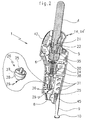
- the cryogenic chain shown in Figure 2 is disposed substantially in line and in its axis, inside an ergonomic housing 11 whose middle part 12 ( Figure 1) serves as a handle for a grip full-handed adult user; preferably, the middle part 12 of the housing 11 is in fact globally convex on the proximal side (that is, on the side of the the user), to come and marry the curvature of his thumb ; in addition a recess 13 in the upper part on this side of the housing 11, allows an approach movement and toggle the user's thumb to operate the control of the device as it will be said further without to break the contact of the base of the thumb with the housing 11; distal side (that is, the most away from the user) the middle part of the housing is globally concave to ensure a complete take by the four fingers, providing a good grip of the device 1 by one hand 2 of the user adult and allow, by one or the other of his four fingers, simultaneously actuate trigger 6 for control the throwing of gas 7.
- the housing 11 is preferably made of two half-shells 14,14 'of identical shape, assembled one against the other in the vertical vertical plane of housing 11.
- the general shape of each half-shell 14, 14 ' is shown in plan in FIG. 2, on the internal side housing 11; the outer shape of each half-shell 14, 14 'is shown in front view in FIG. 1 and in side views, in Figure 4 for the proximal view and in Figure 5 for the distal view.
- the middle portion 12 of the housing constituting the grasping device of the apparatus has a medium section as it fits perfectly in the hand of an adult but that, conversely, she hardly in the hand of a child; thus, the latter will it be difficult to take the device with a only hand, which, in addition to the electrical safety that will be specified later, constitutes an element determining for the safety of children.
- cryogenic chain of the device 1 arranged substantially in line in the axis of said apparatus, and maintained in a good position thanks to housing provided for in inside the half-shells 14 and 14 'in which just fit each of the elements constituting the chain so that after assembly of the two half-shells 14,14 ' the whole is completely rigid.
- the cryogenic chain comprises successively, in upper part of the apparatus 1, a support 20 welcoming on the upper side the withdrawal head 21 of the cartridge 4 through a nut 22 forming part connection and on the other side, a nut 23 supporting a filter that will be specified later, a solenoid valve in line 24 intended to put the gas in communication under its liquid form from cartridge 4 with the system ejection and expansion of the gas consisting of a tubing 25 small internal diameter of the order of 0.5 mm.
- the tubing 25 of the system ejection and relaxation is associated with a sleeve cylindro-conical 26 shown in Figure 2 following a tearing up on a larger scale;
- the sleeve 26 is mounted coaxially thanks to a radial wedge formed of at least three fins so that the cylindrical portion 27 having an internal diameter larger than the tubing 25, creates an air passage around said tubing 25;
- the temperature and the outlet pressure of the ejection and expansion system of the gas by giving the opening calibrated 8 in part lower housing 11 a general form of nozzle, by example tulip flared towards the nozzle 29 and arranged in the same axis, at a good distance to mix ambient air sucked through the lights 31 through VENTURI effect generated by the propulsion of the gas.
- Cartridge 4 of CO 2 is in fact a cartridge conventionally comprising a cylindrical metal container, closed at one end, quite similar but of a larger size.
- a withdrawal head 21 arranged to cooperate with a support 20.
- the extraction head 21 consists of an externally threaded cylindrical tip, a cap 401 which is intended to close the cartridge before its introduction into the device and a nut 22 threaded internally and externally, the internal thread of the nut 22 being screwed onto the thread of the tip of the withdrawal head 21 to maintain Place the lid 401.
- the cartridge 4 is in principle disposable taking into account its particular use but could be recharged if necessary; the cartridges contain CO 2 in sufficient quantity for a treatment of approximately 15 seconds.
- the withdrawal system comprises, as in prior art, an automatic percussion system of the cartridge, ensuring the necessary sealing during and after the perforation of the cap 401 for example bronze, closing the cartridge 4.
- the no screw of the nut 22 which is screwed above the withdrawal head 21 of the cartridge 4 was deliberately chosen from unusual steps, so that it is not possible to use non-compliant cartridges.
- a cylindrical support 20 comprising, on the cartridge side, a first inlet chamber 201 threaded internally into which the nut 22 previously mounted on the head is screwed. withdrawing 21 closed by the bronze cover 401; in the axis of this first chamber 201 and therein, a second chamber 202, of smaller diameter, collaborates with the end 221 of the nut 22 of smaller diameter than the threaded portion of said nut to ensure a total sealing, thanks to an outer O-ring 222 mounted around said end 221, between the cartridge 4 and the rest of the device, as soon as the firing pin 35 perforates the cap 401.
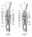
- the striker 35 forming the second part of the system is constituted of a tip 36 and is integral with the support 20 which can engage in the hollow end portion 223 of the nut 22 surrounding the withdrawal head 21 to come into contact with the lid 401 when the engagement said nut 22 in the support 20 is sufficient to secure the assembly; at this moment, the tip 36 is in contact with the cap 401 and the O-ring 222 is in contact with the walls of the chamber 202 ensuring its sealing with the withdrawal head 21; it then suffices, as shown in Figure 7, to continue to screw the assembly, cartridge 4 / nut 22 inside the support 20 to perforate the lid 401; the CO 2 can then relax towards the downstream portion of the support 20 by first passing through a longitudinal channel 37 provided for this purpose in the axis of the striker 35 which opens into a third coaxial chamber 203 of the support 20 necessary for the setting in place of the percussion system and supporting in the flow of liquid CO 2 , a filter 38 for retaining any residues contained in the cartridge 4.
- the filter 38 is capped by a nut 23 cooperating with an internal thread of the chamber 203 in a conventional manner.
- the nut 23 is traversed axially by a channel 231 and is provided on its downstream face with a threaded pin allowing the inlet of the solenoid valve 24 to be subsequently implanted.
- the latter selected from high pressure solenoid valves, allows the opening and closing of an axial channel extending the previous channel 231 by simple control of an electromagnet disposed in the axis of the solenoid valve.
- the expansion tube 25 is mounted, extending, if necessary, in the cylindrical-conical sleeve 27 thermally controlling the flow of CO 2 .
- the expansion tube 25 is given a very small internal diameter, of the order of 0.5 mm; in order to avoid the formation of an ice plug at the outlet of the expansion tube, a PTFE tube is preferably used and taking into account the CO 2 pressure of the order of 50 bars at the outlet of the cartridge 4 , the rate of CO 2 flow inside the tube 25 is large enough to discharge the micronized particle dry ice to the outside.
- the solenoid valve 24 powered by batteries 41 advantageously arranged in a housing 42 ( Figures 3 and 5) in the part upper distal face of the housing 11 ( Figure 5) and controlled, ie powered up, by the support simultaneously of the two switches 5 and 6 connected in series in the power supply, that is to say between batteries 41 and the coil of the solenoid valve 24; like him has already been said, and to avoid any particular manipulation by children, the relative position of the two switches 5 and 6 projecting from the housing 11 is such that when the middle part of said housing is in the hand of an adult, the first switch 5, preferably in the form of a push button, come overall under the thumb of the user and the second switch 6, advantageously in the form of a trigger, can be operated by at least one of the other four fingers of the hand.
- the two switches 5 and 6 were respectively for this purpose from else of the case 11 diametrically opposed in its plane median.
- the apparatus 1 which has just been described can be advantageously complemented by a complementary organ of control of the temperature of the area of use so to avoid that the favorable lowering of temperature for the treatment does not cause tissue necrosis;
- a threshold detector of temperature 45 coupled to a control electronics and able to operate remotely without contact with the area use or care according to Figures 2 and 3.
- the detector optics 45 Placed in the lower part of the housing 11 so that the detector optics 45 is centered in the direction of the area to be treated, we chose in a preferred way, as temperature threshold detector, an infrared pyrometer preferably operating with a power supply continuous 12 volts like solenoid valve 24; in practice, the focal length of the optics of the pyrometer 45 is chosen so that the field of view also matches completely as possible to the target to be measured on the epidermis in order to get a temperature reading just and precise.
- the position of the pyrometer 45 is precisely calculated so that its distance to the area of treatment is neither too short because then the gradient thermal of the skin becomes so important that the temperature of the treated area and temperature of the area scrutinized by the pyrometer are very far apart, with the consequence of randomizing the alarm setpoint, nor too far away which would almost certainly lead to a superposition between the dry ice jet and the radiation infra-red, with the consequence that the pyrometer would more surely raise the temperature of the jet than that of the area to watch.
- the threshold detector of the pyrometer 45 is set at a temperature of the order of 5 ° C to maintain a safety margin; according to a first embodiment, when the temperature threshold of the pyrometer 45 is reached, the control electronics associated with it, prevents by an audible or visual signal the user and / or can cut off the supply of the solenoid valve 24, abruptly stopping the CO 2 projection; according to another embodiment, the pyrometer 45 may send an audible or visual signal when a first threshold of danger is reached and cut the solenoid valve 24 when a second threshold is reached, for example around 2 ° C.
- the apparatus 1 according to the invention can be simply used by any adult and non-professional user. For this, it will suffice to apprehend with his right hand for example, the middle portion 12 of the housing 11 of the device, to introduce in its upper part a new cartridge 4 and aim it in its support 20 to get the percussion of its operculum 401; the device is then ready for use and it will be sufficient for the adult user to approach the epidermis 3 on which it is desired to operate a cryotherapy by holding it vertically until the end 10 of the crutch 9 is in contact with the area to be treated; at this time and maintaining the device vertically, it is sufficient for the user to simultaneously press the button 5 with the thumb and the trigger 6 with his index finger to trigger the solenoid valve 24 and thus the projection 7 of a flow of CO 2 in liquid / solid phase.
- the cartridge of the apparatus is provided for a single operation, that is to say to bring the area to be treated from a temperature of about 32 ° C to a temperature between 2 and 5 ° C, and this, in about 15 seconds.
- the thermal safety of the device but we will nevertheless observe that when the device is incorrectly positioned voluntarily or not, that is to say, it is no longer in the vertical axis allowing the crutch 9 to fully play its role of spacer, the diameter of the cartridge 4 is such that very quickly the flow propelled by the nozzle 29 of the ejection and expansion system is in fact gaseous form therefore safe from the point of view thermal for the epidermis.
- the crutch 9 to have at a good distance the nozzle 29 of the ejection system can be replaced by a hollowed base of cylindrical, frustoconical or trunk-pyramidal stem from the bottom of the housing 11 and extending downward substantially in the axis of said housing on a determined length to ensure a sufficient safety distance as previously explained about the stand 9.
- This hollow base device Moreover, it has the advantage of a better stability of the device at rest and naturally avoids any error positioning the device over the area of the epidermis to be treated.
Landscapes
- Health & Medical Sciences (AREA)
- Surgery (AREA)
- Life Sciences & Earth Sciences (AREA)
- Nuclear Medicine, Radiotherapy & Molecular Imaging (AREA)
- Animal Behavior & Ethology (AREA)
- Veterinary Medicine (AREA)
- Biomedical Technology (AREA)
- Heart & Thoracic Surgery (AREA)
- Medical Informatics (AREA)
- Molecular Biology (AREA)
- Otolaryngology (AREA)
- General Health & Medical Sciences (AREA)
- Public Health (AREA)
- Engineering & Computer Science (AREA)
- Thermotherapy And Cooling Therapy Devices (AREA)
- Catching Or Destruction (AREA)
- Surgical Instruments (AREA)
- Infusion, Injection, And Reservoir Apparatuses (AREA)
- Filling Or Discharging Of Gas Storage Vessels (AREA)
- Toys (AREA)
- Telephonic Communication Services (AREA)
- Telephone Set Structure (AREA)
Description
- la figure 1 représente une vue générale de l'appareil conforme à l'invention maintenu verticalement dans la main droite d'un utilisateur, à distance correcte de l'épiderme à traiter,
- la figure 2 représente en élévation et en coupe verticale médiane l'appareil suivant la ligne II/II de la figure 4, montrant la structure interne des organes ainsi que leur position relative dans l'appareil,
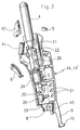
- la figure 3 est une vue en élévation et en perspective de l'appareil dont on a enlevé une des demi-coquilles formant l'enveloppe pour montrer les organes internes représentés de manière arrachée mais en position relative de fonctionnement.
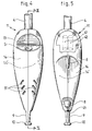
- la figure 4 est une vue en élévation de face (proximale) de l'appareil monté,
- la figure 5 est une vue en élévation de l'arrière (distale) de l'appareil monté,
- la figure 6 est une représentation partielle et à plus grande échelle de la chaíne cryogénique montrant le détail de la tête de soutirage d'une cartouche de gaz montée sur son support à l'intérieur de l'appareil, juste avant la percussion de son opercule de fermeture,
- la figure 7 est la même que la figure précédente, sauf que la cartouche est représentée totalement engagée sur son support après percussion de son opercule.
Claims (17)
- Appareil autonome de cryothérapie manipulable avec une seule main, utilisant la température et la pression de détente d'un gaz liquéfié projeté en phase au moins partiellement solide sur un épiderme (3) humain ou animal, tel que du CO2 ou équivalent, contenu sous pression dans une cartouche (4) amovible, dont la tête de soutirage (21), qui est reliée par un support (20) à un système commandé d'éjection et de détente du gaz liquéfié, est telle que, pendant toute la durée d'une projection, seule la partie liquide du gaz à l'intérieur de la cartouche vienne au contact de ladite tête de soutirage caractérisé en ce que le support (20) de la cartouche et le système commandé d'éjection et de détente sont disposés sensiblement en ligne et dans l'axe de l'appareil, à l'intérieur d'un boítier (11) ergonomique d'axe correspondant à celui de l'appareil, dont la partie médiane sert de poignée pour une prise à pleine main (2) de l'utilisateur adulte et comporte l'organe de commande du système commandé d'éjection et de détente du gaz, dont la partie supérieure présente une entrée pour introduire dans son support la cartouche (4), tête en bas et dans l'axe du boítier (11), et la percuter, ou pour la retirer après usage, et dont la partie inférieure comporte une ouverture calibrée (8) formant un passage pour le gaz en projection sensiblement dans l'axe du boítier et des moyens (9) pour tenir à distance requise la buse de sortie (29) du système commandé d'éjection et de détente par rapport à la zone de l'épiderme à traiter.
- Appareil selon la revendication précédente caractérisé en ce que le système commandé d'éjection et de détente comprend une électrovanne (24) en ligne avec une tubulure (25) d'éjection du gaz liquéfié.
- Appareil selon la revendication 2 caractérisé en ce que l'organe de commande de l'ouverture de l'électrovanne (24) est constitué par deux interrupteurs (5,6) actionnables par la main (2) de l'utilisateur et montés en série dans l'alimentation électrique (41) de l'électrovanne (24), l'actionnement de l'électrovanne nécessitant l'appui simultané des deux interrupteurs (5,6) par la main (2) de l'utilisateur.
- Appareil selon la revendication 3 caractérisé en ce que la position relative des deux interrupteurs (5,6) venant en saillie sur le boítier (11) est telle que, lorsque la partie médiane (12) dudit boítier est dans la main (2) d'un adulte, le premier interrupteur, par exemple en forme de bouton-poussoir (5), vienne globalement sous le pouce de l'utilisateur et le deuxième interrupteur, avantageusement en forme de gâchette (6), puisse être actionné par un ou plusieurs des quatre autres doigts de la main (2).
- Appareil selon la revendication 4 caractérisé en ce que la partie médiane (12) du boítier (11) est conformé pour une prise en main totale d'un utilisateur adulte, c'est-à-dire globalement convexe du côté proximal pour suivre la courbure du pouce, un évidement (13) dans la partie supérieure du boítier (11) permettant le mouvement d'approche du pouce sans rompre le contact de sa base avec le boítier, et globalement concave du côté distal pour une prise complète des autres doigts.
- Appareil selon la revendication 1 caractérisé en ce que le système commandé d'éjection et de détente comprend une vanne manuelle par exemple à piston disposé transversalement à l'axe de l'appareil, couplée en amont à la tête de soutirage de la cartouche (21) et en aval au système de détente et d'éjection du gaz liquéfié.
- Appareil selon l'une quelconque des revendications 2 à 6 caractérisé en ce que la tubulure (25) du système d'éjection et de détente du gaz liquéfié est une tubulure de faible diamètre intérieur, de l'ordre de 0,5 mm.
- Appareil selon l'une quelconque des revendications précédentes caractérisé en ce que les moyens pour tenir la buse (29) du système d'éjection à distance requise de l'épiderme à traiter (3) sont constitués d'une excroissance du type d'une béquille (9)ou d'un socle évidé de forme cylindrique, tronconique, tronc-pyramidale prévu pour coiffer largement la zone à traiter, issue de la partie inférieure du boítier (11) et s'étendant vers le bas sensiblement parallèlement à l'axe dudit boítier sur une longueur déterminée pour tenir la distance requise, lorsque l'appareil (1) est mis en place au droit de l'épiderme (3).
- Appareil selon l'une quelconque des revendications précédentes caractérisé en ce que la cartouche (4) comprend un corps tubulaire fermé à une extrémité et présentant à l'autre extrémité une tête de soutirage (21) constituée d'un embout cylindrique fileté extérieurement, d'un opercule (401) qui est destiné à fermer la cartouche avant sa mise en place dans l'appareil.
- Appareil selon la revendication 9 avec l'une quelconque des revendications 1 à 5, 7, 8 caractérisé en ce que la tête de soutirage (21) de la cartouche est munie d'un un écrou (22) fileté intérieurement et extérieurement, le filetage intérieur de l'écrou (22) étant vissé sur le filetage de l'embout de la tête de soutirage (21) pour maintenir en place l'opercule (401)
- Appareil selon l'une ou l'autre des revendications 9 ou 10 caractérisé en ce que la cartouche (4) est solidarisée au support de cartouche (20) dans l'appareil par vissage de manière à amener d'abord l'opercule (401) au contact d'un organe de percussion (35) avantageusement fixe, s'étendant dans l'axe du support (20), puis à percer ledit opercule (401) en assurant l'étanchéité du montage afin de soutirer le gaz en phase liquide par un canal axial (37) traversant de part en part le dispositif de percussion, relié en aval à son extrémité libre au système commandé de détente, un trou de purge (40) entre l'espace intérieur du support (20) et l'extérieur étant prévu radialement dans la partie dudit support (20) ne comprenant pas l'organe de percussion (35) pour purger le gaz résiduel dans la cartouche vide pendant son dévissage et avant sa complète désolidarisation de l'appareil.
- Appareil selon l'une quelconque des revendications précédentes caractérisé en ce qu'il comprend des moyens de contrôle du gaz projeté qui consistent à entourer la tubulure (25) de sortie du système d'éjection et de détente par un manchon cylindrico-conique (26) monté coaxialement grâce à un calage radial dont la partie cylindrique (27) a un diamètre interne plus grand que la tubulure (25) pour créer un passage d'air tout autour de ladite tubulure et dont le sommet de la partie tronconique (28) prolongeant la partie cylindrique (27) vient affleurer l'extrémité de la tubulure (25) formant la buse d'éjection (29) en ménageant un espace annulaire pour le passage d'air nettement plus faible que dans la partie cylindrique (27), pour créer par effet VENTURI une aspiration de l'air ambiant au travers de lumières (31) aménagées à la base du boítier (11) et limiter ainsi la température et la pression dans la région à traiter.
- Appareil selon l'une quelconque des revendications précédentes caractérisé en ce qu'il comprend des moyens de contrôle du gaz projeté constitués par la disposition de l'ouverture calibrée (8) en partie inférieure du boítier (11) a la forme générale d'une tuyère en tulipe évasée en direction de la buse (29) de la tubulure (25) et est disposée dans le même axe, à bonne distance de ladite buse et par des lumières (31) aménagées à la base du boítier (11) de manière à mélanger au gaz liquéfié en cours de détente de l'air ambiant aspiré au travers de lumières (31) par effet VENTURI créé par la propulsion du gaz.
- Appareil selon l'une quelconque des revendications précédentes caractérisé en ce qu'il comprend un moyen de contrôle thermique de l'épiderme (3) qui est un détecteur de température (45) de l'épiderme (3) agissant sans contact avec celui-ci.
- Appareil selon la revendication 14 caractérisé en ce que le détecteur est un pyromètre à infrarouge (45).
- Appareil selon la revendication 15 caractérisé en ce que la distance focale du pyromètre à infrarouge (45) est telle d'une part qu'il n'y ait pas d'interaction avec la pulvérisation du gaz liquéfié, et d'autre part que la mesure précise de température se fasse lorsque l'appareil (1) est positionné à distance convenable pour l'utilisation envisagée.
- Appareil selon l'une quelconque des revendications 15 ou 16 caractérisé en ce que le pyromètre à infrarouge (45) est couplé à une alarme visuelle et/ou sonore lorsque la baisse de température de la zone d'utilisation atteint un seuil prédéterminé, le pyromètre (45) pouvant alors avantageusement, mais pas nécessairement, couper automatiquement l'alimentation électrique de l'électrovanne (24).
Applications Claiming Priority (3)
| Application Number | Priority Date | Filing Date | Title |
|---|---|---|---|
| FR0013128 | 2000-10-13 | ||
| FR0013128A FR2815246B1 (fr) | 2000-10-13 | 2000-10-13 | Appareil autonome et portable de cryotherapie a usage grand public |
| PCT/FR2001/003190 WO2002030309A1 (fr) | 2000-10-13 | 2001-10-15 | Appareil a main de cryotherapie par projection |
Publications (2)
| Publication Number | Publication Date |
|---|---|
| EP1328205A1 EP1328205A1 (fr) | 2003-07-23 |
| EP1328205B1 true EP1328205B1 (fr) | 2005-03-30 |
Family
ID=8855316
Family Applications (1)
| Application Number | Title | Priority Date | Filing Date |
|---|---|---|---|
| EP01978533A Expired - Lifetime EP1328205B1 (fr) | 2000-10-13 | 2001-10-15 | Appareil a main de cryotherapie par projection |
Country Status (13)
| Country | Link |
|---|---|
| US (1) | US6960202B2 (fr) |
| EP (1) | EP1328205B1 (fr) |
| JP (1) | JP4078204B2 (fr) |
| CN (1) | CN1219495C (fr) |
| AT (1) | ATE291882T1 (fr) |
| AU (1) | AU2002210639A1 (fr) |
| CA (1) | CA2425328C (fr) |
| DE (1) | DE60109801T2 (fr) |
| DK (1) | DK1328205T3 (fr) |
| ES (1) | ES2240529T3 (fr) |
| FR (1) | FR2815246B1 (fr) |
| PT (1) | PT1328205E (fr) |
| WO (1) | WO2002030309A1 (fr) |
Families Citing this family (97)
| Publication number | Priority date | Publication date | Assignee | Title |
|---|---|---|---|---|
| DE20305694U1 (de) * | 2003-04-08 | 2004-08-19 | 3Rd Angle (U.K.) Ltd., Highley | Tragbares Kryotherapiegerät |
| FR2858303B1 (fr) * | 2003-07-31 | 2005-09-16 | Persee Medica | Dispositif et procede de delivrance d'un fluide |
| US7572255B2 (en) * | 2004-02-03 | 2009-08-11 | Covidien Ag | Gas-enhanced surgical instrument |
| EP1586277B1 (fr) * | 2004-04-16 | 2007-05-09 | Wieslaw Brojek | Cryoapplicateur pour refroidir une surface localement |
| FR2885539B1 (fr) * | 2005-04-28 | 2008-01-25 | Persee Medica | Dispositif d'application d'un fluide sur une zone a traiter comprenant une buse d'ejection amelioree |
| EP1733753A1 (fr) * | 2005-06-14 | 2006-12-20 | RIZK, Nelly Kamel | Appareil pour l'application d'une composition |
| RU2291673C1 (ru) * | 2005-08-09 | 2007-01-20 | Государственное образовательное учреждение высшего профессионального образования "Нижегородская государственная медицинская академия Федерального Агентства по здравоохранению и социальному развитию" (ГОУ ВПО "НижГМА Росздрава") | Способ криогенного лечения заболеваний шейки матки |
| BRPI0706055B8 (pt) | 2006-04-28 | 2021-06-22 | Zeltiq Aesthetics Inc | sistema e conjunto de componentes para remover calor de células subcutâneas ricas em lipídios |
| US20080027419A1 (en) * | 2006-07-25 | 2008-01-31 | Ams Research Corporation | Cryoprobe with Integral Agent Delivery Device |
| ES2533580T3 (es) * | 2006-08-28 | 2015-04-13 | The Regents Of The University Of California | Enfriamiento dinámico de la piel humana usando un agente criogénico no tóxico sin agotamiento del ozono y mínimo potencial de calentamiento global |
| WO2008144552A1 (fr) * | 2007-05-17 | 2008-11-27 | Pro-Dex, Inc. | Dispositif médical portatif |
| DE102007027786A1 (de) | 2007-06-16 | 2008-12-18 | Damm, Hans | Ventil in einer Vorrichtung für die Kryotherapie |
| US20100087806A1 (en) * | 2008-10-07 | 2010-04-08 | Vandolay, Inc. | Automated Cryogenic Skin Treatment |
| RU2444323C2 (ru) * | 2008-12-17 | 2012-03-10 | Валентин Николаевич Павлов | Криораспылитель |
| GB2467349A (en) | 2009-01-30 | 2010-08-04 | Alexander James Hanbury Duggan | Pre-treatment thermal transmission agent for wart or corn |
| US20110152850A1 (en) * | 2009-06-23 | 2011-06-23 | Niedbala R Sam | Devices and methods for dispensing a cryogenic fluid |
| US8647337B2 (en) * | 2009-06-23 | 2014-02-11 | Stc Consulting, Llc | Devices and methods for dispensing a cryogenic fluid |
| DE102010016458B4 (de) | 2010-04-15 | 2011-12-15 | Ingo Dreher | Handgeführte Kühlvorrichtung zur Kryotherapie |
| US9717546B2 (en) | 2012-05-21 | 2017-08-01 | Jhpiego Corporation | Cryotherapy device and method for the treatment of cervical precancerous lesions |
| DE102012013534B3 (de) | 2012-07-05 | 2013-09-19 | Tobias Sokolowski | Vorrichtung für repetitive Nervenstimulation zum Abbau von Fettgewebe mittels induktiver Magnetfelder |
| ITTO20130018A1 (it) * | 2013-01-11 | 2014-07-12 | Marco Ginepro | Pistola refrigeratrice istantanea per bicchieri |
| US8989708B2 (en) * | 2013-05-21 | 2015-03-24 | Verizon Patent And Licensing Inc. | Network device access ID assignment and management |
| US10610279B2 (en) | 2014-04-10 | 2020-04-07 | Channel Medsystems, Inc. | Apparatus and methods for regulating cryogenic treatment |
| US9431817B2 (en) * | 2014-05-30 | 2016-08-30 | Microsoft Technology Licensing, Llc | Battery isolation circuit |
| EP2952179A1 (fr) * | 2014-06-05 | 2015-12-09 | Medical Brands Research B.V. | Traitement d'une lésion de la peau |
| WO2016090152A1 (fr) * | 2014-12-03 | 2016-06-09 | 623 Medical, Llc | Distributeur |
| EP3045132A1 (fr) * | 2015-01-13 | 2016-07-20 | Starpharm | Traitement cosmétique des taches brunes cutanées |
| US11491342B2 (en) | 2015-07-01 | 2022-11-08 | Btl Medical Solutions A.S. | Magnetic stimulation methods and devices for therapeutic treatments |
| EP3295993B1 (fr) * | 2015-05-15 | 2019-10-16 | Beautygun S.L. | Dispositif pour l'administration d'un produit cosmétique, procédé et conteneurs correspondants |
| US10821295B1 (en) | 2015-07-01 | 2020-11-03 | Btl Medical Technologies S.R.O. | Aesthetic method of biological structure treatment by magnetic field |
| US11266850B2 (en) | 2015-07-01 | 2022-03-08 | Btl Healthcare Technologies A.S. | High power time varying magnetic field therapy |
| US20180001107A1 (en) | 2016-07-01 | 2018-01-04 | Btl Holdings Limited | Aesthetic method of biological structure treatment by magnetic field |
| US10695576B2 (en) | 2015-07-01 | 2020-06-30 | Btl Medical Technologies S.R.O. | Aesthetic method of biological structure treatment by magnetic field |
| US10695575B1 (en) | 2016-05-10 | 2020-06-30 | Btl Medical Technologies S.R.O. | Aesthetic method of biological structure treatment by magnetic field |
| US10478633B2 (en) | 2015-07-01 | 2019-11-19 | Btl Medical Technologies S.R.O. | Aesthetic method of biological structure treatment by magnetic field |
| US10709894B2 (en) | 2015-07-01 | 2020-07-14 | Btl Medical Technologies S.R.O. | Aesthetic method of biological structure treatment by magnetic field |
| US10471269B1 (en) | 2015-07-01 | 2019-11-12 | Btl Medical Technologies S.R.O. | Aesthetic method of biological structure treatment by magnetic field |
| US11253717B2 (en) | 2015-10-29 | 2022-02-22 | Btl Healthcare Technologies A.S. | Aesthetic method of biological structure treatment by magnetic field |
| CN105266883A (zh) * | 2015-12-04 | 2016-01-27 | 常州瑞海英诺医疗科技有限公司 | 治疗枪 |
| US11247039B2 (en) | 2016-05-03 | 2022-02-15 | Btl Healthcare Technologies A.S. | Device including RF source of energy and vacuum system |
| US11464993B2 (en) | 2016-05-03 | 2022-10-11 | Btl Healthcare Technologies A.S. | Device including RF source of energy and vacuum system |
| US11534619B2 (en) | 2016-05-10 | 2022-12-27 | Btl Medical Solutions A.S. | Aesthetic method of biological structure treatment by magnetic field |
| US10709895B2 (en) | 2016-05-10 | 2020-07-14 | Btl Medical Technologies S.R.O. | Aesthetic method of biological structure treatment by magnetic field |
| US10583287B2 (en) | 2016-05-23 | 2020-03-10 | Btl Medical Technologies S.R.O. | Systems and methods for tissue treatment |
| US10556122B1 (en) | 2016-07-01 | 2020-02-11 | Btl Medical Technologies S.R.O. | Aesthetic method of biological structure treatment by magnetic field |
| US11141219B1 (en) | 2016-08-16 | 2021-10-12 | BTL Healthcare Technologies, a.s. | Self-operating belt |
| USD843053S1 (en) * | 2016-11-08 | 2019-03-12 | Fenghua Bida Machinery Manufacture Co., Ltd. | Cosmetic sprayer |
| KR101905830B1 (ko) | 2016-11-15 | 2018-10-08 | 울산과학기술원 | 국부 냉각 마취 장치, 국부 냉각 마취 장치의 제어 방법 및 국부 냉각 마취 장치의 냉각 온도 조절기 |
| USD820972S1 (en) * | 2016-12-20 | 2018-06-19 | Pronova Laboratories B.V. | Wart freezing device |
| CN106726102A (zh) * | 2017-01-13 | 2017-05-31 | 镇江市宜尔医疗器械有限公司 | 一种喷射冷疗装置 |
| KR20180131356A (ko) | 2017-05-30 | 2018-12-10 | 주식회사 리센스메디컬 | 의료용 냉각 장치 |
| WO2018221848A1 (fr) | 2017-05-30 | 2018-12-06 | 주식회사 리센스메디컬 | Dispositif médical de refroidissement |
| WO2019006027A1 (fr) | 2017-06-30 | 2019-01-03 | R2 Dermatology, Inc. | Dispositifs de cryopulvérisation dermatologiques comprenant un réseau linéaire de buses et procédés d'utilisation |
| CA3068911A1 (fr) * | 2017-07-19 | 2019-01-24 | Dutch Renewable Energy B.V. | Systeme de distribution pour utilisation dans un traitement cryogenique de la peau |
| US20190021777A1 (en) * | 2017-07-20 | 2019-01-24 | Jhpiego Corporation | Cryotherapy Device For The Treatment of Cervical Precancerous Lesions |
| US10349997B1 (en) | 2017-11-27 | 2019-07-16 | Lewis O'Reilly | Cryogenic treatment system |
| FR3076200B1 (fr) | 2017-12-28 | 2023-04-14 | Cryobeauty Pharma | Buse d'application pour dispositif de traitement dermo-cosmetique des taches brunes cutanees par cryotherapie cyto-selective |
| KR102517065B1 (ko) | 2017-12-29 | 2023-04-03 | 주식회사 리센스메디컬 | 냉각발생장치 |
| CN108273183B9 (zh) * | 2018-01-30 | 2021-02-05 | 河南煜博医疗器械制造有限公司 | 利用co2急速降温的低温冲击镇痛设备 |
| KR102145098B1 (ko) * | 2018-04-27 | 2020-08-18 | 울산과학기술원 | 의료용 냉각장치 |
| PT3785682T (pt) | 2018-04-27 | 2023-03-28 | Recensmedical Inc | Aparelho de arrefecimento e método de arrefecimento |
| KR102160855B1 (ko) * | 2018-04-27 | 2020-09-28 | 울산과학기술원 | 의료용 냉각방법 및 의료용 냉각장치 |
| FR3082712B1 (fr) * | 2018-06-26 | 2020-07-31 | Oreal | Systeme d'injection sans aiguille |
| CN112955099B (zh) | 2018-07-27 | 2024-04-26 | 雷森斯医疗有限公司 | 医疗冷却装置和使用其的冷却方法 |
| CA3107932A1 (fr) | 2018-07-31 | 2020-02-06 | Zeltiq Aesthetics, Inc. | Procedes, dispositifs et systemes pour l'amelioration d'une ou de plusieurs caracteristiques de la peau |
| US11666479B2 (en) | 2018-08-19 | 2023-06-06 | Recensmedical, Inc. | Device for cooling anesthesia by chilled fluidic cooling medium |
| CN109259929A (zh) * | 2018-11-30 | 2019-01-25 | 张少君 | 一种心内科止血抢救装置 |
| KR102735829B1 (ko) | 2018-12-07 | 2024-11-29 | 주식회사 리센스메디컬 | 냉각장치 및 냉각방법 |
| PL3897428T3 (pl) * | 2018-12-17 | 2024-08-26 | Cryoconcepts Lp | Urządzenie do modulowania przepływu dla dozowania płynów pod ciśnieniem |
| EP3669803A1 (fr) * | 2018-12-20 | 2020-06-24 | Oystershell NV | Stylo de formation de comprimés de dioxyde de carbone |
| WO2020132602A1 (fr) | 2018-12-21 | 2020-06-25 | R2 Technologies, Inc. | Systèmes de commande et de positionnement automatiques pour dispositifs de cryopulvérisation dermatologiques |
| EP3897427B1 (fr) | 2018-12-21 | 2024-05-01 | R2 Technologies, Inc. | Système de planification de traitement de cryopulvérisation dermatologique automatisé |
| US12558146B2 (en) | 2019-04-11 | 2026-02-24 | Btl Medical Solutions A.S. | Methods and devices for aesthetic treatment of biological structures by radiofrequency and magnetic energy |
| US12156689B2 (en) | 2019-04-11 | 2024-12-03 | Btl Medical Solutions A.S. | Methods and devices for aesthetic treatment of biological structures by radiofrequency and magnetic energy |
| PL4417249T3 (pl) | 2019-04-11 | 2026-04-20 | Btl Medical Solutions A.S. | Urządzenia do zabiegów na strukturach biologicznych za pomocą częstotliwości radiowej |
| KR200493630Y1 (ko) * | 2019-06-19 | 2021-05-06 | 이상봉 | 극저온 치료장치 |
| USD921211S1 (en) | 2019-06-21 | 2021-06-01 | Recensmedical, Inc. | Medical cooling device |
| USD921911S1 (en) | 2019-06-21 | 2021-06-08 | Recensmedical, Inc. | Medical cooling device |
| USD1015533S1 (en) | 2019-11-07 | 2024-02-20 | 623 Medical, Llc | Vapocoolant device |
| US11878167B2 (en) | 2020-05-04 | 2024-01-23 | Btl Healthcare Technologies A.S. | Device and method for unattended treatment of a patient |
| ES2993637T3 (en) | 2020-05-04 | 2025-01-03 | Btl Healthcare Technologies As | Device for unattended treatment of a patient |
| US12611545B2 (en) | 2020-05-04 | 2026-04-28 | Btl Healthcare Technologies A.S. | Device and method for unattended treatment of a patient |
| US11278341B2 (en) | 2020-07-14 | 2022-03-22 | Recensmedical, Inc. | Method of safely using controlled cooling systems and devices |
| USD977633S1 (en) | 2020-08-07 | 2023-02-07 | Recensmedical, Inc. | Cradle for a medical cooling device |
| USD968626S1 (en) | 2020-08-07 | 2022-11-01 | Recensmedical, Inc. | Medical cooling device |
| USD968627S1 (en) | 2020-08-07 | 2022-11-01 | Recensmedical, Inc. | Medical cooling device |
| JP2023539054A (ja) * | 2020-08-14 | 2023-09-13 | ゼルティック エステティックス インコーポレイテッド | 身体輪郭形成のためのマルチアプリケータシステム及び方法 |
| US12364531B2 (en) | 2021-02-16 | 2025-07-22 | RecensMedical, Inc.; | Methods for treating skin disorders using precision cooling technology |
| CA3260012A1 (fr) | 2021-10-13 | 2023-04-20 | Btl Medical Solutions A.S. | Dispositifs de traitement esthétique de structures biologiques par énergie radiofréquence et magnétique |
| US11896816B2 (en) | 2021-11-03 | 2024-02-13 | Btl Healthcare Technologies A.S. | Device and method for unattended treatment of a patient |
| KR20250007521A (ko) * | 2022-03-31 | 2025-01-14 | 주식회사 리센스메디컬 | 냉각 장치용 경사를 가지는 어플리케이터 팁 |
| US20250281323A1 (en) * | 2022-03-31 | 2025-09-11 | Recensmedical, Inc. | Methods of use of precision and controlled cooling devices in combination with other treatments |
| EP4684688A3 (fr) | 2022-07-01 | 2026-03-18 | Recensmedical, Inc. | Module de mélange utilisé pour un dispositif de fourniture de fluide frigorigène |
| US20240099753A1 (en) * | 2022-09-23 | 2024-03-28 | Dgi Group Llc | Skin tag removal devices |
| CN117122808A (zh) * | 2023-08-25 | 2023-11-28 | 上海康乃馨医疗科技有限公司 | 美容装置 |
| US20260097227A1 (en) | 2024-10-08 | 2026-04-09 | Btl Medical Solutions A.S. | Devices and methods for application of a magnetic field to the nervous system |
| USD1075002S1 (en) * | 2024-12-13 | 2025-05-13 | Shenzhen Haige Cross Border Technology Co., Ltd. | Liquid nitrogen cryotherapy device |
Family Cites Families (6)
| Publication number | Priority date | Publication date | Assignee | Title |
|---|---|---|---|---|
| DE69318706T2 (de) | 1993-07-06 | 1999-01-14 | Cryonic Medical, Salins Les Bains | Einrichtung für die Kryotherapie |
| DE19548652C2 (de) * | 1995-12-15 | 1999-12-30 | Helga Steinfatt | Handapparat zur Erzeugung von Kälte für die Therapie in der Medizin und die Kosmetik |
| US5901723A (en) * | 1997-03-19 | 1999-05-11 | Ames; Russell R. | Security cane with pepper spray dispenser |
| US5916212A (en) * | 1998-01-23 | 1999-06-29 | Cryomedical Sciences, Inc. | Hand held cyrosurgical probe system |
| FR2775589B1 (fr) | 1998-03-06 | 2000-04-28 | Cryonic Medical | Appareil autonome et portable de cryogenie utilisant l'anhydride carbonique en phase liquide/solide |
| JP3729322B2 (ja) * | 2000-02-03 | 2005-12-21 | フジノン株式会社 | 内視鏡の手元操作部 |
-
2000
- 2000-10-13 FR FR0013128A patent/FR2815246B1/fr not_active Expired - Fee Related
-
2001
- 2001-10-15 PT PT01978533T patent/PT1328205E/pt unknown
- 2001-10-15 US US10/398,733 patent/US6960202B2/en not_active Expired - Lifetime
- 2001-10-15 EP EP01978533A patent/EP1328205B1/fr not_active Expired - Lifetime
- 2001-10-15 JP JP2002533758A patent/JP4078204B2/ja not_active Expired - Fee Related
- 2001-10-15 AU AU2002210639A patent/AU2002210639A1/en not_active Abandoned
- 2001-10-15 CA CA2425328A patent/CA2425328C/fr not_active Expired - Fee Related
- 2001-10-15 DK DK01978533T patent/DK1328205T3/da active
- 2001-10-15 AT AT01978533T patent/ATE291882T1/de active
- 2001-10-15 DE DE60109801T patent/DE60109801T2/de not_active Expired - Lifetime
- 2001-10-15 WO PCT/FR2001/003190 patent/WO2002030309A1/fr not_active Ceased
- 2001-10-15 CN CNB018189393A patent/CN1219495C/zh not_active Expired - Fee Related
- 2001-10-15 ES ES01978533T patent/ES2240529T3/es not_active Expired - Lifetime
Also Published As
| Publication number | Publication date |
|---|---|
| FR2815246A1 (fr) | 2002-04-19 |
| JP4078204B2 (ja) | 2008-04-23 |
| FR2815246B1 (fr) | 2003-01-24 |
| DK1328205T3 (da) | 2005-08-08 |
| DE60109801T2 (de) | 2006-02-16 |
| WO2002030309A1 (fr) | 2002-04-18 |
| ES2240529T3 (es) | 2005-10-16 |
| ATE291882T1 (de) | 2005-04-15 |
| JP2004515270A (ja) | 2004-05-27 |
| EP1328205A1 (fr) | 2003-07-23 |
| DE60109801D1 (de) | 2005-05-04 |
| AU2002210639A1 (en) | 2002-04-22 |
| PT1328205E (pt) | 2005-08-31 |
| CN1474670A (zh) | 2004-02-11 |
| CA2425328C (fr) | 2011-09-20 |
| US20040102768A1 (en) | 2004-05-27 |
| US6960202B2 (en) | 2005-11-01 |
| CN1219495C (zh) | 2005-09-21 |
| CA2425328A1 (fr) | 2002-04-18 |
Similar Documents
| Publication | Publication Date | Title |
|---|---|---|
| CA2425328C (fr) | Appareil a main de cryotherapie par projection | |
| EP1059904B1 (fr) | Appareil autonome et portable de cryogenie utilisant l'anhydride carbonique en phase liquide/solide | |
| CA2515525C (fr) | Dispositif generateur d'une onde de choc a simple coup | |
| CA1315164C (fr) | Appareil d'injection de liquide, notamment a usage de soins dentaires | |
| US5297962A (en) | Dental cleaning device | |
| CH444385A (fr) | Instrument de chirurgie à basse température | |
| FR2858303A1 (fr) | Dispositif et procede de delivrance d'un fluide | |
| FR2479681A1 (fr) | Dispositif pour les operations de cryochirurgie | |
| FR2832140A3 (fr) | Tire-bouchon sur et rapide pour bouteille a bouchon en liege | |
| US20210186090A1 (en) | Water pipe having a mechanism for releasing spent capsules | |
| ES2983502T3 (es) | Dispositivo de modulación de flujo para dispensar fluidos presurizados | |
| GB2409815A (en) | Cryosurgical instrument | |
| EP3429381A1 (fr) | Organe d'aspiration pour narguile et procede de montage d'un tel organe | |
| CA2605997A1 (fr) | Dispositif d'application d'un fluide sur une zone a traiter comprenant une minuterie | |
| EP0570301A1 (fr) | Dispositif cryogénique portable | |
| MXPA00008542A (en) | Autonomous and portable cryogenic apparatus using carbon dioxide in liquid/solid phase | |
| FR2474857A1 (fr) | Appareil chirurgical plurifonctionnel | |
| EP0185575A1 (fr) | Procédé et dispositif de réchauffage de gaz | |
| FR3163811A1 (fr) | Dispositif dit Roll-on, notamment portatif, en particulier pour des applications médicales, thérapeutiques ou esthétiques. | |
| FR2885059A1 (fr) | Dispositif d'application d'un fluide sur une zone a traiter comprenant une minuterie | |
| FR2717748A1 (fr) | Dispositif de désodorisation de l'atmosphère intérieure d'un véhicule. | |
| EP1249258A1 (fr) | Extincteur destiné à la formation de personnel à la lutte contre le feu. | |
| FR2796709A1 (fr) | Dispositif de soufflage d'air a tres basse temperature | |
| BE392890A (fr) | ||
| BE466532A (fr) |
Legal Events
| Date | Code | Title | Description |
|---|---|---|---|
| PUAI | Public reference made under article 153(3) epc to a published international application that has entered the european phase |
Free format text: ORIGINAL CODE: 0009012 |
|
| 17P | Request for examination filed |
Effective date: 20030502 |
|
| AK | Designated contracting states |
Designated state(s): AT BE CH CY DE DK ES FI FR GB GR IE IT LI LU MC NL PT SE TR |
|
| AX | Request for extension of the european patent |
Extension state: AL LT LV MK RO SI |
|
| GRAP | Despatch of communication of intention to grant a patent |
Free format text: ORIGINAL CODE: EPIDOSNIGR1 |
|
| GRAS | Grant fee paid |
Free format text: ORIGINAL CODE: EPIDOSNIGR3 |
|
| GRAA | (expected) grant |
Free format text: ORIGINAL CODE: 0009210 |
|
| RAP1 | Party data changed (applicant data changed or rights of an application transferred) |
Owner name: VALLOUREC COMPOSANTS AUTOMOBILES VITRY Owner name: CRYONIC MEDICAL |
|
| AK | Designated contracting states |
Kind code of ref document: B1 Designated state(s): AT BE CH CY DE DK ES FI FR GB GR IE IT LI LU MC NL PT SE TR |
|
| PG25 | Lapsed in a contracting state [announced via postgrant information from national office to epo] |
Ref country code: IE Free format text: LAPSE BECAUSE OF FAILURE TO SUBMIT A TRANSLATION OF THE DESCRIPTION OR TO PAY THE FEE WITHIN THE PRESCRIBED TIME-LIMIT Effective date: 20050330 |
|
| REG | Reference to a national code |
Ref country code: GB Ref legal event code: FG4D Free format text: NOT ENGLISH |
|
| REG | Reference to a national code |
Ref country code: CH Ref legal event code: EP |
|
| REF | Corresponds to: |
Ref document number: 60109801 Country of ref document: DE Date of ref document: 20050504 Kind code of ref document: P |
|
| REG | Reference to a national code |
Ref country code: IE Ref legal event code: FG4D Free format text: LANGUAGE OF EP DOCUMENT: FRENCH |
|
| REG | Reference to a national code |
Ref country code: GR Ref legal event code: EP Ref document number: 20050402026 Country of ref document: GR |
|
| REG | Reference to a national code |
Ref country code: SE Ref legal event code: TRGR |
|
| REG | Reference to a national code |
Ref country code: CH Ref legal event code: NV Representative=s name: R. A. EGLI & CO. PATENTANWAELTE |
|
| REG | Reference to a national code |
Ref country code: DK Ref legal event code: T3 |
|
| GBT | Gb: translation of ep patent filed (gb section 77(6)(a)/1977) |
Effective date: 20050728 |
|
| REG | Reference to a national code |
Ref country code: PT Ref legal event code: SC4A Effective date: 20050628 |
|
| PG25 | Lapsed in a contracting state [announced via postgrant information from national office to epo] |
Ref country code: CY Free format text: LAPSE BECAUSE OF FAILURE TO SUBMIT A TRANSLATION OF THE DESCRIPTION OR TO PAY THE FEE WITHIN THE PRESCRIBED TIME-LIMIT Effective date: 20051015 |
|
| REG | Reference to a national code |
Ref country code: ES Ref legal event code: FG2A Ref document number: 2240529 Country of ref document: ES Kind code of ref document: T3 |
|
| PG25 | Lapsed in a contracting state [announced via postgrant information from national office to epo] |
Ref country code: MC Free format text: LAPSE BECAUSE OF NON-PAYMENT OF DUE FEES Effective date: 20051031 |
|
| REG | Reference to a national code |
Ref country code: IE Ref legal event code: FD4D |
|
| PLBE | No opposition filed within time limit |
Free format text: ORIGINAL CODE: 0009261 |
|
| STAA | Information on the status of an ep patent application or granted ep patent |
Free format text: STATUS: NO OPPOSITION FILED WITHIN TIME LIMIT |
|
| 26N | No opposition filed |
Effective date: 20060102 |
|
| REG | Reference to a national code |
Ref country code: FR Ref legal event code: PLFP Year of fee payment: 16 |
|
| REG | Reference to a national code |
Ref country code: FR Ref legal event code: PLFP Year of fee payment: 17 |
|
| PGFP | Annual fee paid to national office [announced via postgrant information from national office to epo] |
Ref country code: CH Payment date: 20170926 Year of fee payment: 17 Ref country code: GB Payment date: 20170925 Year of fee payment: 17 Ref country code: IT Payment date: 20170921 Year of fee payment: 17 Ref country code: FR Payment date: 20170921 Year of fee payment: 17 Ref country code: GR Payment date: 20170929 Year of fee payment: 17 Ref country code: LU Payment date: 20170922 Year of fee payment: 17 Ref country code: FI Payment date: 20170921 Year of fee payment: 17 |
|
| PGFP | Annual fee paid to national office [announced via postgrant information from national office to epo] |
Ref country code: DK Payment date: 20170921 Year of fee payment: 17 Ref country code: BE Payment date: 20170922 Year of fee payment: 17 Ref country code: SE Payment date: 20170925 Year of fee payment: 17 Ref country code: NL Payment date: 20170925 Year of fee payment: 17 |
|
| PGFP | Annual fee paid to national office [announced via postgrant information from national office to epo] |
Ref country code: DE Payment date: 20170920 Year of fee payment: 17 Ref country code: TR Payment date: 20171004 Year of fee payment: 17 |
|
| PGFP | Annual fee paid to national office [announced via postgrant information from national office to epo] |
Ref country code: AT Payment date: 20170921 Year of fee payment: 17 Ref country code: ES Payment date: 20171102 Year of fee payment: 17 Ref country code: PT Payment date: 20171002 Year of fee payment: 17 |
|
| REG | Reference to a national code |
Ref country code: DE Ref legal event code: R119 Ref document number: 60109801 Country of ref document: DE |
|
| REG | Reference to a national code |
Ref country code: DK Ref legal event code: EBP Effective date: 20181031 |
|
| REG | Reference to a national code |
Ref country code: SE Ref legal event code: EUG |
|
| REG | Reference to a national code |
Ref country code: CH Ref legal event code: PL |
|
| REG | Reference to a national code |
Ref country code: NL Ref legal event code: MM Effective date: 20181101 |
|
| REG | Reference to a national code |
Ref country code: AT Ref legal event code: MM01 Ref document number: 291882 Country of ref document: AT Kind code of ref document: T Effective date: 20181015 |
|
| GBPC | Gb: european patent ceased through non-payment of renewal fee |
Effective date: 20181015 |
|
| REG | Reference to a national code |
Ref country code: BE Ref legal event code: MM Effective date: 20181031 |
|
| PG25 | Lapsed in a contracting state [announced via postgrant information from national office to epo] |
Ref country code: LU Free format text: LAPSE BECAUSE OF NON-PAYMENT OF DUE FEES Effective date: 20181015 |
|
| PG25 | Lapsed in a contracting state [announced via postgrant information from national office to epo] |
Ref country code: FI Free format text: LAPSE BECAUSE OF NON-PAYMENT OF DUE FEES Effective date: 20181015 Ref country code: PT Free format text: LAPSE BECAUSE OF NON-PAYMENT OF DUE FEES Effective date: 20190415 Ref country code: DE Free format text: LAPSE BECAUSE OF NON-PAYMENT OF DUE FEES Effective date: 20190501 Ref country code: NL Free format text: LAPSE BECAUSE OF NON-PAYMENT OF DUE FEES Effective date: 20181101 Ref country code: SE Free format text: LAPSE BECAUSE OF NON-PAYMENT OF DUE FEES Effective date: 20181016 |
|
| PG25 | Lapsed in a contracting state [announced via postgrant information from national office to epo] |
Ref country code: BE Free format text: LAPSE BECAUSE OF NON-PAYMENT OF DUE FEES Effective date: 20181031 Ref country code: CH Free format text: LAPSE BECAUSE OF NON-PAYMENT OF DUE FEES Effective date: 20181031 Ref country code: GR Free format text: LAPSE BECAUSE OF NON-PAYMENT OF DUE FEES Effective date: 20190506 Ref country code: LI Free format text: LAPSE BECAUSE OF NON-PAYMENT OF DUE FEES Effective date: 20181031 Ref country code: FR Free format text: LAPSE BECAUSE OF NON-PAYMENT OF DUE FEES Effective date: 20181031 |
|
| PG25 | Lapsed in a contracting state [announced via postgrant information from national office to epo] |
Ref country code: GB Free format text: LAPSE BECAUSE OF NON-PAYMENT OF DUE FEES Effective date: 20181015 Ref country code: AT Free format text: LAPSE BECAUSE OF NON-PAYMENT OF DUE FEES Effective date: 20181015 Ref country code: DK Free format text: LAPSE BECAUSE OF NON-PAYMENT OF DUE FEES Effective date: 20181031 Ref country code: IT Free format text: LAPSE BECAUSE OF NON-PAYMENT OF DUE FEES Effective date: 20181015 |
|
| REG | Reference to a national code |
Ref country code: ES Ref legal event code: FD2A Effective date: 20191202 |
|
| PG25 | Lapsed in a contracting state [announced via postgrant information from national office to epo] |
Ref country code: ES Free format text: LAPSE BECAUSE OF NON-PAYMENT OF DUE FEES Effective date: 20181016 |
|
| PG25 | Lapsed in a contracting state [announced via postgrant information from national office to epo] |
Ref country code: TR Free format text: LAPSE BECAUSE OF NON-PAYMENT OF DUE FEES Effective date: 20181015 |