EP1327796A1 - Hybridkeilriemen-Anordnung - Google Patents
Hybridkeilriemen-Anordnung Download PDFInfo
- Publication number
- EP1327796A1 EP1327796A1 EP02000571A EP02000571A EP1327796A1 EP 1327796 A1 EP1327796 A1 EP 1327796A1 EP 02000571 A EP02000571 A EP 02000571A EP 02000571 A EP02000571 A EP 02000571A EP 1327796 A1 EP1327796 A1 EP 1327796A1
- Authority
- EP
- European Patent Office
- Prior art keywords
- support elements
- arrangement according
- belt
- belt arrangement
- elements
- Prior art date
- Legal status (The legal status is an assumption and is not a legal conclusion. Google has not performed a legal analysis and makes no representation as to the accuracy of the status listed.)
- Granted
Links
- 239000002131 composite material Substances 0.000 title 1
- 239000000463 material Substances 0.000 claims description 10
- 238000013016 damping Methods 0.000 claims description 9
- 238000004026 adhesive bonding Methods 0.000 claims description 2
- 238000004049 embossing Methods 0.000 claims description 2
- 238000004073 vulcanization Methods 0.000 claims description 2
- 239000011248 coating agent Substances 0.000 description 4
- 238000000576 coating method Methods 0.000 description 4
- 230000002146 bilateral effect Effects 0.000 description 1
- 238000010276 construction Methods 0.000 description 1
- 238000011161 development Methods 0.000 description 1
- 230000018109 developmental process Effects 0.000 description 1
- 239000007787 solid Substances 0.000 description 1
Images



Classifications
-
- F—MECHANICAL ENGINEERING; LIGHTING; HEATING; WEAPONS; BLASTING
- F16—ENGINEERING ELEMENTS AND UNITS; GENERAL MEASURES FOR PRODUCING AND MAINTAINING EFFECTIVE FUNCTIONING OF MACHINES OR INSTALLATIONS; THERMAL INSULATION IN GENERAL
- F16G—BELTS, CABLES, OR ROPES, PREDOMINANTLY USED FOR DRIVING PURPOSES; CHAINS; FITTINGS PREDOMINANTLY USED THEREFOR
- F16G5/00—V-belts, i.e. belts of tapered cross-section
- F16G5/16—V-belts, i.e. belts of tapered cross-section consisting of several parts
- F16G5/166—V-belts, i.e. belts of tapered cross-section consisting of several parts with non-metallic rings
Definitions
- the invention relates to a hybrid V-belt and pulley (s) V-belt arrangement according to the preamble of the main claim.
- engaging belt means generate with their movement periodically recurring geometric shapes, noises whose frequencies are suitable for the human ear in striking and unpleasant tonal components of the Make running noise noticeable.
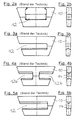
- Powerful hybrid V-belts consist of tension members to accommodate the Workers in the longitudinal direction of the belt and from support elements of various possible Designs (Fig. 2 to Fig. 5, front and side views, respectively).
- the support elements are as completely enclosing (Fig. 2) or slotted elements (Fig. 3 to Fig. 5) executed that receive one (Fig. 2, Fig. 3, Fig. 5) or two tension members (Fig. 4).
- the torque to be transmitted is frictionally transmitted by a drive pulley wedge-shaped groove on the belt and from this in the same way to the Transfer driven pulley.
- the support elements serve to increase the Transverse stiffness of the hybrid belt assembly and take the axial contact forces from the flanks of the disks.
- the support elements which are toothed by positive locking Tension members or connected to smooth tension members by friction or clamping are repeated and at regular intervals due to the rotating speed of the belt Clearances in contact with and in contact with the input and output disks with each other, which creates the disturbing tonal noise components mentioned.
- the regularly recurring contact of the support elements with the disks and the elements with one another to reduce the tonal components in the running noise is disturbed by the fact that the sequence of the support elements is positively influenced by a thickness varying in the circumferential direction.
- the targeted combination of elements of different strengths significantly improves the noise level by breaking up the constant sequence of operations.
- the varying strength of the support elements can be realized in different ways become: On the one hand by one-sided or two-sided, then symmetrical or asymmetrical change in the basic body thickness in the running direction or to the other by applying an additional layer of another material.
- the generation of noise is minimized by the additionally applied layer in comparison in the direction of the front or back made of highly damping material is made to the base body or flat between the support elements Intermediate pieces of damping material are arranged.
- the additional layer can be by material bonding (gluing, vulcanization) or by form-fitting elements on the layer and base body on at least one of the four Surfaces can be attached to the front or back.
- the thickness of the extra layer can also vary over the radial extent.
- Another way to disrupt the uniformity of the sequence of operations is to vary the pitch on the tension members leading the support elements (additionally).
- Hybrid V-belts 4 running on pulleys 6 usually consist of an 8th or two endless tension members 8a, 8b whereupon support elements (support blocks) 10, 10a, 10b, ... are arranged (prior art: FIGS. 2 to 5).
- the V-belt arrangement 2 shown in detail in Fig. 1 a consists of a Hybrid V-belt 4 and a pulley 6, the hybrid V-belt 4 in This case consists of an (endless) tension member 8 and arranged thereon There are support elements 10 which are supported on the groove flanks of the pulley 6.
- the basic structure of the support elements 10 is comparable to the embodiment according to FIG. 2a. 1b shows the relevant longitudinal section through the support element 10 and tension member 8.
- Fig. 6 shows a number of lined up support elements (10a, 10b, ...) through unilateral or bilateral, symmetrical or asymmetrical change in Base body stronger of the support elements is characterized in the running direction, so that at constant distance of the depressions or embossments on the tension member in the direction of travel a varying spacing sequence 16a, 16b, ... of support elements is created.
- the support element 10 shown in FIG. 8 has the front and rear in the running direction a coating on.
- Front-rear asymmetry can be realized, which changes the tonal component of the Impact noise reduced.
- damping material is in the form of a flat intermediate piece 26 between inserted two support elements 10a, 10b.
- 10a / 10b shows a damping device arranged on the front upper partial surface 28
- Layer element 24, which is form-fitting with the base body of the support element 10 is connected by two projecting cylindrical elevations on the layer element 24 36 are fitted into corresponding depressions 38 of the base body.
- 11a / 11b likewise shows an example on the front upper partial surface 28 arranged damping layer element 24, the angular by means of an elevation 36 Cross-section and corresponding recess 38 is connected in the base body.
Landscapes
- Engineering & Computer Science (AREA)
- General Engineering & Computer Science (AREA)
- Mechanical Engineering (AREA)
- Devices For Conveying Motion By Means Of Endless Flexible Members (AREA)
- Prostheses (AREA)
- Belt Conveyors (AREA)
- Transmissions By Endless Flexible Members (AREA)
Abstract
Description
Bei gleichbleibender Teilung der Zugträger wird durch gezielte Kombination verschieden starker Elemente das Geräuschniveau durch Aufbrechen der gleichbleibenden Eingriffsfolge entscheidend verbessert.
Es zeigt:
- Fig. 6 eine Reihe erfindungsgemäßer Stützelemente unterschiedlicher Stärke (Schnitt in Riemenlängsrichtung);
- Fig. 7 einen Abschnitt aus einem erfindungsgemäßen Zugträger mit variabler Teilung;
- Fig. 8 ein Stützelement in Seitenansicht (bzw. Schnitt in Riemenlängsrichtung) mit auf (in Laufrichtung) Vorder- und Rückseite angebrachter Schicht; und
- Fig. 9 zwei Stützelemente, ebenfalls in Seitenansicht (bzw. Schnitt in Riemenlängsrichtung) mit einem flächigen Zwischenstück.
- Fig. 10a, Fig. 10b und Fig. 11a, Fig. 11b zeigen zwei Stützelemente mit formschlüssigen Elementen an Schicht und Grundkörper, jeweils in Seitenansicht und von vorn.
- 2
- Keilriemenanordnung
- 4
- Hybridkeilriemen
- 6
- Riemenscheibe
- 8, 8a, 8b
- Zugträger (Lastträger)
- 10, 10a, 10b,
- Stützelement (Stützblock)
- 12, 12a, 12b
- Schlitz (im Stützelement)
- 14, 14a, 14b,
- Vertiefung(en), Prägung(en) (Teilungen)
- 16a, 16b,
- Abstandsfolge (Grundkörperstärke)
- 18a, 18b,
- Beabstandung (der Stützelemente voneinander)
- 20
- Vorderseite des Stützelements
- 22
- Rückseite des Stützelements
- 24, 24a, 24b,
- Schichtelement
- 26
- Zwischenstück
- 28, 30
- Flächen (oben, unten) an Vorderseite
- 32, 34
- Flächen (oben, unten) an Rückseite
- 36
- Erhebung
- 38
- Vertiefung
Claims (11)
- Aus Hybridkeilriemen (4) und Riemenscheibe(n) (6) bestehende Keilriemenanordnung (2),
wobei der Hybridkeilriemen (4) Stützelemente (10a, 10b, ...) aufweist,
die jeweils mit mindestens einem Schlitz (12 bzw. 12a, 12b, ...) zur Aufnahme mindestens eines Zugträgers (8, bzw. 8a, 8b) versehen sind,
dadurch gekennzeichnet, dass die Folge der mit der mindestens einen Riemenscheibe (6) in Eingriff gelangenden Stützelemente (10a, 10b, ...) eine in Umlaufrichtung der mindestens einen Riemenscheibe (6) variable Frequenz aufweist. - Keilriemenanordnung nach Anspruch 1,
dadurch gekennzeichnet, dass die variable Folge (=Frequenz) der Stützelemente (10) durch Aneinanderreihung verschieden starker Stützelemente (10a, 10b, ...) realisiert ist. - Keilriemenanordnung nach Anspruch 1 oder 2,
dadurch gekennzeichnet, dass die variierende Stärke aufeinanderfolgender Stützelemente (10a, 10b, ...) durch einseitige oder zweiseitige, oder durch symmetrische oder unsymmetrische Veränderung der in Laufrichtung gegebenen Grundkörperstärke (16a. 16b, ...) realisiert ist. - Keilriemenanordnung nach einem der Ansprüche 1 bis 3,
dadurch gekennzeichnet, dass die variierende Stärke aufeinanderfolgender Stützelemente (10a, 10b, ...) durch Anbringung jeweils eines Schichtelementes (24a, 24b) auf in Laufrichtung Vorder- (20) und Rückseite (229 der Stützelemente (10a, 10b, ...). - Keilriemenanordnung nach einem der Ansprüche 1 bis 3,
dadurch gekennzeichnet, dass auf der vorderen oberen Teilfläche (28) ein dämpfendes Schichtelement (24) angeordnet ist, das formschlüssig mit dem Grundkörper des Stützelementes (10) verbunden ist, indem zwei am Schichtelement (24) vorspringende Erhebung (36) in korrespondierende Vertiefungen (38) des Grundkörpers eingepasst sind. - Keilriemenanordnung nach Anspruch 5,
dadurch gekennzeichnet, dass die auf dem Schichtelement (24) vorspringenden Erhebungen (36) und die im Grundkörper dazu korrespondierenden Vertiefungen (38) jeweils zylindrischen oder eckigen Querschnitt aufweisen. - Keilriemenanordnung nach einem der Ansprüche 1 bis 6,
dadurch gekennzeichnet, dass die Stützelemente (10a, 10b, ...) an in Laufrichtung Vorder- (20) und/oder Rückseite (22) mit stark bedämpfendem Material beschichtet sind (Schichtelemente (24 bzw. 24a, 24b). - Keilriemenanordnung nach einem der Ansprüche 1 bis 7,
dadurch gekennzeichnet, dass in Laufrichtung zwischen den Stützelementen (10a, 10b, ...) jeweils ein flächiges Zwischenstück ( 26 ...) aus bedämpfendem Material angeordnet ist. - Keilriemenanordnung nach einem der Ansprüche 1 bis 8,
dadurch gekennzeichnet, dass die auf den Stützelementen (10a, 10b, ...) jeweils angeordneten Schichtelemente (24; bzw. 24a, 24b) durch Stoffschluss (Kleben, Vulkanisation) an mindestens einer der vier an Vorder- (20) und/oder Rückseite (22) der Stützelemente (10a, 10b, ...) befindlichen Flächen (28, 30, 32, 34) angebracht werden. - Keilriemenanordnung nach einem der Ansprüche 1 bis 9,
dadurch gekennzeichnet, dass die radiale Ausdehnung der an in Laufrichtung Vorder- (20) und/oder Rückseite (22) angeordneten Schichtelemente (24; bzw. 24a, 24b) von einem Stützelement (10a, ...) zum nächsten (lOb, ....) variiert. - Keilriemenanordnung nach einem der Ansprüche 1 bis 10,
dadurch gekennzeichnet, dass die Teilung (Prägungen 14a, 14b, ...) an dem Stützelemente (10a, 10b, ...) führenden Zugträger (8 bzw. 8a, 8b) variiert.
Priority Applications (4)
| Application Number | Priority Date | Filing Date | Title |
|---|---|---|---|
| AT02000571T ATE391253T1 (de) | 2002-01-10 | 2002-01-10 | Hybridkeilriemen-anordnung |
| EP02000571A EP1327796B1 (de) | 2002-01-10 | 2002-01-10 | Hybridkeilriemen-Anordnung |
| DE50212012T DE50212012D1 (de) | 2002-01-10 | 2002-01-10 | Hybridkeilriemen-Anordnung |
| HU0300074A HU223738B1 (hu) | 2002-01-10 | 2003-01-09 | Ékszíjelrendezés |
Applications Claiming Priority (1)
| Application Number | Priority Date | Filing Date | Title |
|---|---|---|---|
| EP02000571A EP1327796B1 (de) | 2002-01-10 | 2002-01-10 | Hybridkeilriemen-Anordnung |
Publications (2)
| Publication Number | Publication Date |
|---|---|
| EP1327796A1 true EP1327796A1 (de) | 2003-07-16 |
| EP1327796B1 EP1327796B1 (de) | 2008-04-02 |
Family
ID=8185219
Family Applications (1)
| Application Number | Title | Priority Date | Filing Date |
|---|---|---|---|
| EP02000571A Expired - Lifetime EP1327796B1 (de) | 2002-01-10 | 2002-01-10 | Hybridkeilriemen-Anordnung |
Country Status (3)
| Country | Link |
|---|---|
| EP (1) | EP1327796B1 (de) |
| AT (1) | ATE391253T1 (de) |
| DE (1) | DE50212012D1 (de) |
Cited By (3)
| Publication number | Priority date | Publication date | Assignee | Title |
|---|---|---|---|---|
| WO2005090823A1 (en) * | 2004-03-19 | 2005-09-29 | Dayco Europe S.R.L. Con Unico Socio | Belt for a continuously variable transmission |
| EP1626201A3 (de) * | 2004-08-12 | 2006-03-22 | ContiTech Antriebssysteme GmbH | Traktionsoptimierter Hybridkeilriemen einer Hybridkeilriemen/Scheiben-Anordnung |
| EP2716933A4 (de) * | 2011-05-27 | 2015-03-25 | Toyota Motor Co Ltd | Treibriemen und montageverfahren für treibriemen |
Citations (5)
| Publication number | Priority date | Publication date | Assignee | Title |
|---|---|---|---|---|
| US4457742A (en) * | 1980-07-03 | 1984-07-03 | Nippondenso Co., Ltd. | Torque transmission belt means |
| EP0305023A1 (de) * | 1987-08-24 | 1989-03-01 | Fuji Jukogyo Kabushiki Kaisha | Treibriemen |
| US5152722A (en) * | 1990-07-25 | 1992-10-06 | Nissan Motor Co., Ltd. | Transmission belt assembly |
| JPH07305745A (ja) * | 1994-05-11 | 1995-11-21 | Aichi Mach Ind Co Ltd | 高負荷伝動ベルト |
| JP2001090786A (ja) * | 1999-09-22 | 2001-04-03 | Bando Chem Ind Ltd | 高負荷伝動用vベルト |
-
2002
- 2002-01-10 DE DE50212012T patent/DE50212012D1/de not_active Expired - Lifetime
- 2002-01-10 AT AT02000571T patent/ATE391253T1/de not_active IP Right Cessation
- 2002-01-10 EP EP02000571A patent/EP1327796B1/de not_active Expired - Lifetime
Patent Citations (5)
| Publication number | Priority date | Publication date | Assignee | Title |
|---|---|---|---|---|
| US4457742A (en) * | 1980-07-03 | 1984-07-03 | Nippondenso Co., Ltd. | Torque transmission belt means |
| EP0305023A1 (de) * | 1987-08-24 | 1989-03-01 | Fuji Jukogyo Kabushiki Kaisha | Treibriemen |
| US5152722A (en) * | 1990-07-25 | 1992-10-06 | Nissan Motor Co., Ltd. | Transmission belt assembly |
| JPH07305745A (ja) * | 1994-05-11 | 1995-11-21 | Aichi Mach Ind Co Ltd | 高負荷伝動ベルト |
| JP2001090786A (ja) * | 1999-09-22 | 2001-04-03 | Bando Chem Ind Ltd | 高負荷伝動用vベルト |
Non-Patent Citations (2)
| Title |
|---|
| PATENT ABSTRACTS OF JAPAN vol. 1996, no. 03 29 March 1996 (1996-03-29) * |
| PATENT ABSTRACTS OF JAPAN vol. 2000, no. 21 3 August 2001 (2001-08-03) * |
Cited By (3)
| Publication number | Priority date | Publication date | Assignee | Title |
|---|---|---|---|---|
| WO2005090823A1 (en) * | 2004-03-19 | 2005-09-29 | Dayco Europe S.R.L. Con Unico Socio | Belt for a continuously variable transmission |
| EP1626201A3 (de) * | 2004-08-12 | 2006-03-22 | ContiTech Antriebssysteme GmbH | Traktionsoptimierter Hybridkeilriemen einer Hybridkeilriemen/Scheiben-Anordnung |
| EP2716933A4 (de) * | 2011-05-27 | 2015-03-25 | Toyota Motor Co Ltd | Treibriemen und montageverfahren für treibriemen |
Also Published As
| Publication number | Publication date |
|---|---|
| EP1327796B1 (de) | 2008-04-02 |
| ATE391253T1 (de) | 2008-04-15 |
| DE50212012D1 (de) | 2008-05-15 |
Similar Documents
| Publication | Publication Date | Title |
|---|---|---|
| DE69712148T2 (de) | Zahnkette mit erhöhten Gliedrücken | |
| DE3413384C2 (de) | Laschenkette für stufenlos verstellbare Kegelscheibengetriebe | |
| DE3319963A1 (de) | Keilriemen | |
| EP1855026A2 (de) | Laschenkette | |
| DE3714568C2 (de) | ||
| DE4316877A1 (de) | Lärmgedämpfte Zahnkette | |
| EP0599310B1 (de) | Riementrieb eines Torantriebs | |
| DE20315915U1 (de) | Einlageelement, sowie Führungsanordnung zur Führung von Aufzugkabinen | |
| EP1327796A1 (de) | Hybridkeilriemen-Anordnung | |
| EP1875107A1 (de) | Zugmitteltrieb mit zumindest einer schiene zum spannen und/oder führen eines endlosen zugmittels | |
| EP0778428A1 (de) | Kettenführungs- und Gleitschiene, insbesondere für Brennkraftmaschinen | |
| DE69204523T2 (de) | Treibriemen für ein stufenlos regelbares Getriebe. | |
| DE102018108664A1 (de) | Planetenträger mit schalenförmigen Verbindungselementen | |
| DE3109172C2 (de) | Steuerungsantrieb für Brennkraftmaschinen | |
| DE3038756C1 (de) | Endloser V-foermiger Keilriemen | |
| EP0536527A1 (de) | Zahnriementrieb mit zumindest einer Spannrolle | |
| EP1397603A1 (de) | Schwingungsarmer hybridkeilriemen | |
| DE3844243A1 (de) | Endloser transmissionsriemen | |
| DE102004013207A1 (de) | Spann- oder Gleitschiene für Kettentriebe von Brennkraftmaschinen von Kraftfahrzeugen | |
| DE2906619C2 (de) | Zahnriemen | |
| EP3502015B1 (de) | Fördervorrichtung | |
| WO2003086931A2 (de) | Flachriemen für die aufzugstechnik | |
| DE4016469A1 (de) | Endloser keilriemen mit innenseitigen quernuten | |
| EP0971157B1 (de) | Aus Synchronriemen und Synchronscheibe bestehende formschlüssige Antriebsanordnung | |
| EP0960840A2 (de) | Zahnriemenantrieb mit Mitnehmern |
Legal Events
| Date | Code | Title | Description |
|---|---|---|---|
| PUAI | Public reference made under article 153(3) epc to a published international application that has entered the european phase |
Free format text: ORIGINAL CODE: 0009012 |
|
| AK | Designated contracting states |
Designated state(s): AT BE CH CY DE DK ES FI FR GB GR IE IT LI LU MC NL PT SE TR |
|
| AX | Request for extension of the european patent |
Extension state: AL LT LV MK RO SI |
|
| 17P | Request for examination filed |
Effective date: 20040116 |
|
| AKX | Designation fees paid |
Designated state(s): AT BE CH CY DE DK ES FI FR GB GR IE IT LI LU MC NL PT SE TR |
|
| 17Q | First examination report despatched |
Effective date: 20051223 |
|
| 17Q | First examination report despatched |
Effective date: 20051223 |
|
| GRAP | Despatch of communication of intention to grant a patent |
Free format text: ORIGINAL CODE: EPIDOSNIGR1 |
|
| GRAS | Grant fee paid |
Free format text: ORIGINAL CODE: EPIDOSNIGR3 |
|
| GRAA | (expected) grant |
Free format text: ORIGINAL CODE: 0009210 |
|
| AK | Designated contracting states |
Kind code of ref document: B1 Designated state(s): AT BE CH CY DE DK ES FI FR GB GR IE IT LI LU MC NL PT SE TR |
|
| REG | Reference to a national code |
Ref country code: GB Ref legal event code: FG4D Free format text: NOT ENGLISH |
|
| REG | Reference to a national code |
Ref country code: CH Ref legal event code: EP Ref country code: IE Ref legal event code: FG4D Free format text: LANGUAGE OF EP DOCUMENT: GERMAN |
|
| REF | Corresponds to: |
Ref document number: 50212012 Country of ref document: DE Date of ref document: 20080515 Kind code of ref document: P |
|
| NLV1 | Nl: lapsed or annulled due to failure to fulfill the requirements of art. 29p and 29m of the patents act | ||
| REG | Reference to a national code |
Ref country code: IE Ref legal event code: FD4D |
|
| PG25 | Lapsed in a contracting state [announced via postgrant information from national office to epo] |
Ref country code: PT Free format text: LAPSE BECAUSE OF FAILURE TO SUBMIT A TRANSLATION OF THE DESCRIPTION OR TO PAY THE FEE WITHIN THE PRESCRIBED TIME-LIMIT Effective date: 20080902 Ref country code: NL Free format text: LAPSE BECAUSE OF FAILURE TO SUBMIT A TRANSLATION OF THE DESCRIPTION OR TO PAY THE FEE WITHIN THE PRESCRIBED TIME-LIMIT Effective date: 20080402 Ref country code: ES Free format text: LAPSE BECAUSE OF FAILURE TO SUBMIT A TRANSLATION OF THE DESCRIPTION OR TO PAY THE FEE WITHIN THE PRESCRIBED TIME-LIMIT Effective date: 20080713 Ref country code: FI Free format text: LAPSE BECAUSE OF FAILURE TO SUBMIT A TRANSLATION OF THE DESCRIPTION OR TO PAY THE FEE WITHIN THE PRESCRIBED TIME-LIMIT Effective date: 20080402 |
|
| EN | Fr: translation not filed | ||
| PG25 | Lapsed in a contracting state [announced via postgrant information from national office to epo] |
Ref country code: DK Free format text: LAPSE BECAUSE OF FAILURE TO SUBMIT A TRANSLATION OF THE DESCRIPTION OR TO PAY THE FEE WITHIN THE PRESCRIBED TIME-LIMIT Effective date: 20080402 Ref country code: SE Free format text: LAPSE BECAUSE OF FAILURE TO SUBMIT A TRANSLATION OF THE DESCRIPTION OR TO PAY THE FEE WITHIN THE PRESCRIBED TIME-LIMIT Effective date: 20080702 Ref country code: IE Free format text: LAPSE BECAUSE OF FAILURE TO SUBMIT A TRANSLATION OF THE DESCRIPTION OR TO PAY THE FEE WITHIN THE PRESCRIBED TIME-LIMIT Effective date: 20080402 |
|
| PLBE | No opposition filed within time limit |
Free format text: ORIGINAL CODE: 0009261 |
|
| STAA | Information on the status of an ep patent application or granted ep patent |
Free format text: STATUS: NO OPPOSITION FILED WITHIN TIME LIMIT |
|
| 26N | No opposition filed |
Effective date: 20090106 |
|
| PG25 | Lapsed in a contracting state [announced via postgrant information from national office to epo] |
Ref country code: MC Free format text: LAPSE BECAUSE OF NON-PAYMENT OF DUE FEES Effective date: 20090131 |
|
| REG | Reference to a national code |
Ref country code: CH Ref legal event code: PL |
|
| GBPC | Gb: european patent ceased through non-payment of renewal fee |
Effective date: 20090110 |
|
| PG25 | Lapsed in a contracting state [announced via postgrant information from national office to epo] |
Ref country code: CY Free format text: LAPSE BECAUSE OF FAILURE TO SUBMIT A TRANSLATION OF THE DESCRIPTION OR TO PAY THE FEE WITHIN THE PRESCRIBED TIME-LIMIT Effective date: 20080402 |
|
| PG25 | Lapsed in a contracting state [announced via postgrant information from national office to epo] |
Ref country code: CH Free format text: LAPSE BECAUSE OF NON-PAYMENT OF DUE FEES Effective date: 20090131 Ref country code: LI Free format text: LAPSE BECAUSE OF NON-PAYMENT OF DUE FEES Effective date: 20090131 |
|
| PG25 | Lapsed in a contracting state [announced via postgrant information from national office to epo] |
Ref country code: GB Free format text: LAPSE BECAUSE OF NON-PAYMENT OF DUE FEES Effective date: 20090110 |
|
| PG25 | Lapsed in a contracting state [announced via postgrant information from national office to epo] |
Ref country code: BE Free format text: LAPSE BECAUSE OF NON-PAYMENT OF DUE FEES Effective date: 20090131 |
|
| PG25 | Lapsed in a contracting state [announced via postgrant information from national office to epo] |
Ref country code: AT Free format text: LAPSE BECAUSE OF NON-PAYMENT OF DUE FEES Effective date: 20090110 |
|
| PG25 | Lapsed in a contracting state [announced via postgrant information from national office to epo] |
Ref country code: GR Free format text: LAPSE BECAUSE OF FAILURE TO SUBMIT A TRANSLATION OF THE DESCRIPTION OR TO PAY THE FEE WITHIN THE PRESCRIBED TIME-LIMIT Effective date: 20080703 |
|
| PG25 | Lapsed in a contracting state [announced via postgrant information from national office to epo] |
Ref country code: LU Free format text: LAPSE BECAUSE OF NON-PAYMENT OF DUE FEES Effective date: 20090110 |
|
| PG25 | Lapsed in a contracting state [announced via postgrant information from national office to epo] |
Ref country code: TR Free format text: LAPSE BECAUSE OF FAILURE TO SUBMIT A TRANSLATION OF THE DESCRIPTION OR TO PAY THE FEE WITHIN THE PRESCRIBED TIME-LIMIT Effective date: 20080402 |
|
| PGFP | Annual fee paid to national office [announced via postgrant information from national office to epo] |
Ref country code: DE Payment date: 20120131 Year of fee payment: 11 |
|
| PGFP | Annual fee paid to national office [announced via postgrant information from national office to epo] |
Ref country code: IT Payment date: 20120125 Year of fee payment: 11 |
|
| PG25 | Lapsed in a contracting state [announced via postgrant information from national office to epo] |
Ref country code: FR Free format text: LAPSE BECAUSE OF FAILURE TO SUBMIT A TRANSLATION OF THE DESCRIPTION OR TO PAY THE FEE WITHIN THE PRESCRIBED TIME-LIMIT Effective date: 20090123 |
|
| PG25 | Lapsed in a contracting state [announced via postgrant information from national office to epo] |
Ref country code: DE Free format text: LAPSE BECAUSE OF NON-PAYMENT OF DUE FEES Effective date: 20130801 |
|
| REG | Reference to a national code |
Ref country code: DE Ref legal event code: R119 Ref document number: 50212012 Country of ref document: DE Effective date: 20130801 |
|
| PG25 | Lapsed in a contracting state [announced via postgrant information from national office to epo] |
Ref country code: IT Free format text: LAPSE BECAUSE OF NON-PAYMENT OF DUE FEES Effective date: 20130110 |