BACKGROUND
The invention relates to cleaning devices and more particularly devices for
cleaning paint spray guns.
SUMMARY
The present invention provides an apparatus for cleaning a spraying end of
a paint sprayer. The apparatus includes a solvent vessel having an opening and
containing a solvent. The opening is configured to receive the spraying end of the
paint sprayer. A rotatable brush is only partially submerged in the solvent such
that the spraying end contacts the brush when the spraying end is inserted into the
opening. A motor (e.g. a pneumatic motor) is interconnected with and provides
rotation to the brush. A signal generator is operable to provide an actuation signal
that activates the motor such that the brush rotates and cleans paint from the
spraying end of the paint sprayer.
The brush preferably includes a plurality of flexible bristles and is
mounted within the vessel such that a portion of the brush is below the solvent
level and a portion of the brush is above the solvent level. Preferably, the motor is
configured to rotate the brush in alternating directions each time the spraying end
is inserted into the opening. The brush preferably rotates about a substantially
horizontal brush axis that is below the solvent level and the spraying end may be
inserted into the opening substantially perpendicularly to the brush axis. The
spraying end preferably contacts an outer surface of the brush during cleaning.
The signal generator may include a limit switch that is positioned adjacent
the opening. The limit switch may be configured to provide the actuation signal
in response to insertion of the spraying end into the opening. The vessel may also
include a top wall and the opening may be smaller than the top wall.
The present invention also provides a method for cleaning a spraying end
of a paint spray gun. The method includes providing a solvent vessel defining a
chamber that contains a solvent at a solvent level. A rotatable brush is partially
submerged in the solvent within the vessel such that a portion of the brush is
above the solvent level. The spraying end of the paint spray gun is inserted into
the chamber through the opening and the brush is rotated. The spraying end
engages the exposed portion of the brush and paint is removed from the spraying
end.
A motor may be operably connected to the brush, and a limit switch may
be provided that communicates with the motor. The limit switch preferably
operates in response to the insertion of the spraying end into the chamber. In this
regard, the limit switch signals the motor to rotate upon insertion of the spraying
end into the chamber.
The present invention also provides a paint spraying system for
electronically controlled painting of a product. The system includes an enclosure,
a conveying apparatus for conveying the product through the enclosure, and an
electronic controller. A manipulator is positioned within the enclosure and
operates in response to signals received from the electronic controller. The
manipulator is operable to provide movement in a plurality of directions to a paint
spraying nozzle that is coupled to the manipulator for movement therewith. A
cleaning box is positioned within the enclosure and contains a solvent. The
cleaning box includes an opening and houses a rotatable brush. A signal generator
communicates with the rotatable brush and the brush rotates in response to an
actuation signal provided by the signal generator.
In response to receiving a cleaning signal from the controller, the
manipulator inserts the paint spraying nozzle through the opening and into the
cleaning box. The signal generator signals the brush to rotate, and the nozzle
contacts the rotating brush such that paint is cleaned from the nozzle.
BRIEF DESCRIPTION OF THE DRAWINGS
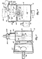
Fig. 1 is a rear left perspective view of a paint spray gun cleaner
embodying the present invention.
Fig. 2 is a front right perspective view of the paint spray gun cleaner.
Fig. 3 is a top view of the paint spray gun cleaner with the lid in an open
position.
Fig. 4 is a section view taken along line 4-4 of Fig. 1.
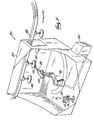
Fig. 5 is a perspective view, with a portion cut away, of an automated paint
spraying booth including a paint spray gun cleaner of the present invention.
Before one embodiment of the invention is explained in detail, it is to be
understood that the invention is not limited in its application to the details of
construction and the arrangements of the components set forth in the following
description or illustrated in the drawings. The invention is capable of other
embodiments and of being practiced or being carried out in various ways. Also, it
is understood that the phraseology and terminology used herein is for the purpose
of description and should not be regarded as limiting. The use of "including" and
"comprising" and variations thereof herein is meant to encompass the items listed
thereafter and equivalents thereof as well as additional items. The use of
"consisting of" and variations thereof herein is meant to encompass only the items
listed thereafter. The use of letters to identify elements of a method or process is
simply for identification and is not meant to indicate that the elements should be
performed in a particular order.
DETAILED DESCRIPTION
Figs. 1 and 2 illustrate a paint spray gun cleaner 10 of the present
invention. The cleaner includes a solvent container 12 supported by a leg 16 that
is secured to or supported by the floor of a paint spraying area. A lid 20 is
pivotally coupled to the container 12 by hinges 22 and is movable between an
open position and a closed position. The lid 20 includes an aperture 24 that
provides access to the container 12 when the lid 20 is in the closed position. A
latch 26 is also provided to secure the lid 20 in the closed position. A pneumatic
motor 28 is secured to an external side wall 30 of the container 12 and is coupled
to air lines 32A, 32B. A signal generator in the form of a limit switch 36 is
mounted to the lid 20 and electrically communicates with an air solenoid 40
through wires 44. The air solenoid 40 receives compressed air from an air
compressor (not shown) and cooperates with the limit switch 36 to regulate the
delivery of the compressed air to the pneumatic motor 28 as described further
below.
Referring now also to Figs. 3 and 4, the pneumatic motor 28 includes a
rotatable drive shaft 48 extending through the side wall 30 and into the container
12. A brush 52 is secured to the end of the drive shaft 48 for rotation therewith
about a brush axis 56. The brush 52 includes a plurality of bristles 60 extending
radially from the brush axis 56. In some embodiments, the bristles 60 are
constructed of Nylon®. An appropriate brush 52 for use with the present invention
is available from McMaster-Carr Supply Company of Elmhurst, IL as Item #
4747A62.
The container 12 is partially filled with a liquid solvent solution 64 to a
solvent level 68. The solvent level 68 is regulated such that a submerged portion
72 of the brush 52 is below the solvent level 68 and submerged in the solvent
solution 64, and an exposed portion 76 of the brush 52 is above the solvent level
68 and not submerged in the solvent solution 64. The solvent level 68 is
preferably maintained above the drive shaft 48 for optimal performance of the
spray gun cleaner 10. A suitable solvent solution 64 for use with the present
invention is Poly-Purge® brand solvent solution, which is available from PPG
Industries, Inc. of Pittsburgh, PA.
The spray gun cleaner 10 is particularly well suited for use in an
automated paint spraying line 80 as illustrated in Fig. 5. The spraying line 80
includes an enclosure 84 having a product conveyor 88 passing therethrough. The
conveyor 88 is of conventional design and conveys a product 92 from one end of
the enclosure 84 to the other. The spraying line 80 also includes an electronically
controlled manipulator 96 operating in response to signals received from a
controller 100. The manipulator 96 includes an end effector 104 that has a paint
spraying nozzle 108. The manipulator 96 guides the end effector 104 along a
predetermined path to apply paint to the product 92 as the product 92 is conveyed
through the enclosure 84.
As the paint spraying nozzle 108 sprays paint upon the individual products
92, paint begins to accumulate on a tip 112 of the nozzle 108. If an excessive
amount of paint accumulates on the tip 112, the quality of the paint spraying
operation will be adversely affected and the aesthetic appearance of the finished
product 92 will degrade. To avoid this situation, the controller 100 is
programmed to provide a cleaning signal to the manipulator 96 after a
predetermined quantity of product 92 has been painted. Upon receiving the
cleaning signal, the manipulator 96 guides the end effector 104 toward the spray
gun cleaner 10.
As best illustrated in Figure 4, the manipulator 96 inserts the nozzle 108
through the aperture 24 in the lid 20, and into the container 12. The nozzle 108 is
inserted substantially vertically in the illustrated construction, but may be inserted
at an angle in alternate constructions. In any event, it is preferred to insert the
nozzle 108 substantially perpendicularly to the brush axis 56.
As the tip 112 engages the bristles 60 of the brush 52, a portion of the end
effector 104 contacts a trigger 114 on the limit switch 36. As the end effector 104
engages the trigger 114, an actuation signal is provided to the air solenoid 40 via
the wires 44. Upon receipt of the actuation signal, the solenoid 40 opens the first
air line 32A (see Figs. 2, 3) that communicates with an impeller (not shown) of
the pneumatic motor 28 on a first side of the brush axis 56. Pressurized air flows
from the solenoid 40 toward the pneumatic motor 28 and impinges upon and
thereby rotates the impeller in a first direction. The impeller is coupled to the
drive shaft 48 such that rotation of the impeller imparts rotation to the brush 52.
As the brush 52 rotates, solvent solution 64 is applied to the tip 112 of the
nozzle 108 by the exposed bristles 60. The solvent solution 64 thins the paint on
the tip 112, and the bristles 60 loosen and remove the thinned paint from the tip
112. The bristles 60 then rotate back into the solvent solution 64 where the paint
is subsequently rinsed from the bristles 60. The bristles 60 then rotate out of the
solvent solution 64 to once again apply solvent solution 64 to the tip 112 and
further clean the nozzle 108.
The tip 112 is maintained in contact with the rotating brush 52 for a
predetermined amount of time to clean at least a portion of the paint from the tip
112. After the tip 112 has been sufficiently cleaned, the controller 100 signals the
manipulator 96 to remove the nozzle 108 from the container 12, thereby
disengaging the end effector 104 from the trigger 114 of the limit switch 36. The
solenoid 40 then stops the flow of air to the pneumatic motor 28, thereby halting
rotation of the brush 52. The manipulator 96 then guides the nozzle 108 toward
the product 92 to perform additional painting operations.
Each time the predetermined quantity of product 92 has been painted, the
manipulator 96 returns the nozzle 108 to the spray gun cleaner 10. The solenoid
40 is configured such that each subsequent insertion of the nozzle 108 into the
container 12 results in rotation of the brush 52 in alternating directions.
Specifically, the solenoid 40 alternately provides compressed air to the pneumatic
motor 28 via the first air line 32A as described above, and the second air line 32B.
The second air line 32B delivers compressed air to the pneumatic motor 28 such
that it impinges upon the impeller on a second, opposite side of the brush axis 56
as the air from the first air line 32A. As such, delivery of compressed air to the
motor 28 through the first air line 32A rotates the brush 52 in one direction (e.g.
counter-clockwise) and delivery of compressed air to the motor 28 through the
second air line 32B rotates the brush 52 in an opposite direction (e.g. clockwise).
Alternating the direction of rotation of the brush 52 in this manner results
in improved cleaning of the tip 112 and longer life of the brush 52. For example,
a first insertion of the tip 112 into the container 12 will generally clean one side of
the tip 112 more completely than the other side of the tip 112. Similarly, the
bristles 60 are flexed or bent in one direction as they contact the tip 112. A
second insertion of the tip 112 into the container 12 will generally clean the other
side of the tip 112 that was less completely cleaned after the first insertion.
Similarly, the bristles 60 will be flexed or bent in an opposite direction during the
second insertion, thereby facilitating a more even wearing of the brush 52 and
preventing the bristles 60 from becoming permanently bent in one direction.
Alternatively, an electrically powered motor may be provided in place of
the pneumatic motor 28. The electric motor should be selected to have suitable
size and power to impart the required rotation to the brush 60. Appropriate
control circuitry may be provided such that the electrical motor is capable of
rotating the brush 60 in alternating directions substantially as described above
with respect to the pneumatic motor 28. Various other types of motors and
control devices may be suitable as well, so long as they provide adequate
alternating rotation of the brush 60, substantially as described above.
Furthermore, various other sensors, devices, and methods for controlling
the activation of the motor may be utilized in accordance with the present
invention. For example, non-contact type sensors including photocells, proximity
sensors and the like may be adapted for use with the spray gun cleaner 10 to detect
the insertion of the tip 112 into the container 12, and provide an appropriate
actuation signal to the air solenoid 40. Alternatively, the controller 100 may be
configured to provide an actuation signal to the solenoid 40 which corresponds to
the sending of the cleaning signal to the manipulator 96. In this regard, the
actuation signal may be provided simultaneously with the cleaning signal, or may
be delayed with respect to the cleaning signal to allow the manipulator 96 to reach
the spray gun cleaner 10. It should be appreciated that any actuation signal,
whether provided by various types of limit switches or by the controller 100, may
be used to activate the motor 28.
Various features of the invention are set forth in the following claims.