EP1327478B1 - Betätigungskopf einer Saug-Druck-Pumpe zum Ausspritzen eines Produkts aus einem Behältnis - Google Patents
Betätigungskopf einer Saug-Druck-Pumpe zum Ausspritzen eines Produkts aus einem Behältnis Download PDFInfo
- Publication number
- EP1327478B1 EP1327478B1 EP03000259A EP03000259A EP1327478B1 EP 1327478 B1 EP1327478 B1 EP 1327478B1 EP 03000259 A EP03000259 A EP 03000259A EP 03000259 A EP03000259 A EP 03000259A EP 1327478 B1 EP1327478 B1 EP 1327478B1
- Authority
- EP
- European Patent Office
- Prior art keywords
- ejection opening
- actuating head
- product
- piston
- outlet duct
- Prior art date
- Legal status (The legal status is an assumption and is not a legal conclusion. Google has not performed a legal analysis and makes no representation as to the accuracy of the status listed.)
- Expired - Lifetime
Links
- 238000005507 spraying Methods 0.000 title abstract 2
- 238000007789 sealing Methods 0.000 claims description 28
- 239000013013 elastic material Substances 0.000 claims description 7
- 239000000463 material Substances 0.000 claims description 6
- 239000004033 plastic Substances 0.000 claims description 4
- 239000003570 air Substances 0.000 description 11
- 230000000694 effects Effects 0.000 description 4
- 241000894006 Bacteria Species 0.000 description 3
- 241000700605 Viruses Species 0.000 description 3
- 244000052616 bacterial pathogen Species 0.000 description 3
- 239000007789 gas Substances 0.000 description 3
- QVGXLLKOCUKJST-UHFFFAOYSA-N atomic oxygen Chemical compound [O] QVGXLLKOCUKJST-UHFFFAOYSA-N 0.000 description 2
- 230000015572 biosynthetic process Effects 0.000 description 2
- 238000004519 manufacturing process Methods 0.000 description 2
- 239000001301 oxygen Substances 0.000 description 2
- 229910052760 oxygen Inorganic materials 0.000 description 2
- 230000035515 penetration Effects 0.000 description 2
- 239000012815 thermoplastic material Substances 0.000 description 2
- 238000004026 adhesive bonding Methods 0.000 description 1
- 239000012080 ambient air Substances 0.000 description 1
- 230000000903 blocking effect Effects 0.000 description 1
- 238000010276 construction Methods 0.000 description 1
- 238000011109 contamination Methods 0.000 description 1
- 230000002939 deleterious effect Effects 0.000 description 1
- 239000002781 deodorant agent Substances 0.000 description 1
- 230000000881 depressing effect Effects 0.000 description 1
- 238000011161 development Methods 0.000 description 1
- 230000018109 developmental process Effects 0.000 description 1
- 238000006073 displacement reaction Methods 0.000 description 1
- 239000003814 drug Substances 0.000 description 1
- 229940079593 drug Drugs 0.000 description 1
- 235000013305 food Nutrition 0.000 description 1
- 238000007654 immersion Methods 0.000 description 1
- 239000007788 liquid Substances 0.000 description 1
- 235000011837 pasties Nutrition 0.000 description 1
- 230000002035 prolonged effect Effects 0.000 description 1
- 230000007704 transition Effects 0.000 description 1
- 238000003466 welding Methods 0.000 description 1
Images


Classifications
-
- B—PERFORMING OPERATIONS; TRANSPORTING
- B05—SPRAYING OR ATOMISING IN GENERAL; APPLYING FLUENT MATERIALS TO SURFACES, IN GENERAL
- B05B—SPRAYING APPARATUS; ATOMISING APPARATUS; NOZZLES
- B05B11/00—Single-unit hand-held apparatus in which flow of contents is produced by the muscular force of the operator at the moment of use
- B05B11/0005—Components or details
- B05B11/0062—Outlet valves actuated by the pressure of the fluid to be sprayed
- B05B11/0072—A valve member forming part of an outlet opening
-
- B—PERFORMING OPERATIONS; TRANSPORTING
- B05—SPRAYING OR ATOMISING IN GENERAL; APPLYING FLUENT MATERIALS TO SURFACES, IN GENERAL
- B05B—SPRAYING APPARATUS; ATOMISING APPARATUS; NOZZLES
- B05B11/00—Single-unit hand-held apparatus in which flow of contents is produced by the muscular force of the operator at the moment of use
- B05B11/0005—Components or details
- B05B11/0062—Outlet valves actuated by the pressure of the fluid to be sprayed
- B05B11/0064—Lift valves
- B05B11/0067—Lift valves having a valve seat located downstream the valve element
-
- B—PERFORMING OPERATIONS; TRANSPORTING
- B05—SPRAYING OR ATOMISING IN GENERAL; APPLYING FLUENT MATERIALS TO SURFACES, IN GENERAL
- B05B—SPRAYING APPARATUS; ATOMISING APPARATUS; NOZZLES
- B05B11/00—Single-unit hand-held apparatus in which flow of contents is produced by the muscular force of the operator at the moment of use
- B05B11/01—Single-unit hand-held apparatus in which flow of contents is produced by the muscular force of the operator at the moment of use characterised by the means producing the flow
- B05B11/10—Pump arrangements for transferring the contents from the container to a pump chamber by a sucking effect and forcing the contents out through the dispensing nozzle
- B05B11/1001—Piston pumps
-
- B—PERFORMING OPERATIONS; TRANSPORTING
- B05—SPRAYING OR ATOMISING IN GENERAL; APPLYING FLUENT MATERIALS TO SURFACES, IN GENERAL
- B05B—SPRAYING APPARATUS; ATOMISING APPARATUS; NOZZLES
- B05B11/00—Single-unit hand-held apparatus in which flow of contents is produced by the muscular force of the operator at the moment of use
- B05B11/01—Single-unit hand-held apparatus in which flow of contents is produced by the muscular force of the operator at the moment of use characterised by the means producing the flow
- B05B11/10—Pump arrangements for transferring the contents from the container to a pump chamber by a sucking effect and forcing the contents out through the dispensing nozzle
- B05B11/1001—Piston pumps
- B05B11/1016—Piston pumps the outlet valve having a valve seat located downstream a movable valve element controlled by a pressure actuated controlling element
Definitions
- the invention relates to an actuating head of a suction-pressure pump for ejecting a product from a container having a leading to an ejection outlet outlet channel in which a loaded by a spring closure member is arranged, wherein the closure piece in its closed position, the ejection opening under the force of the spring directly seals and released by the pressure exerted by the pressure of the product on actuation of the suction pressure product of the flow through the outlet channel and through the ejection opening against the force of the spring, and wherein a subsequent to the ejection opening first outlet channel of a pipe is surrounded, in which the closure piece is sealingly slidably guided and which is inserted into a bore in the body of the actuating head, which defines between itself and the tube a second outlet channel forming annular space through a third, the wall of the tube Deutschenque ing outlet duct section is connected to the first outlet channel section.
- the closure piece is designed as a valve slide, which is displaceable transversely to an inlet opening of a lying between the closure piece and the ejection opening outlet channel.
- the ejection opening is preceded by a vortex chamber in the outlet channel.
- About the ejection opening of the outlet channel is in any position of the closure piece with the environment in connection. A product residue that is not completely ejected from the outlet channel can therefore come into contact with contaminating and harmful germs, bacteria or viruses contained in the outside or ambient air and with aggressive gases which are harmful to the product, in particular atmospheric oxygen.
- Such deleterious effects are particularly undesirable or dangerous if the product is a food, drug, deodorant, or other product that is ingested or ingested by humans, even if only a small amount of contaminated product remains in the actuator head. Such a contaminated product residue could be ejected at the next operation after prolonged non-operation with and endanger the health of the user.
- a spring-loaded closure body which is inserted into a corresponding receiving space in the actuating head, serves to close the product discharge opening.
- the closure body has, on parts of its outer side, a helically formed groove through which the product to be dispensed can pass, as the product in a rear region of the closure body is conveyed out of the container, which is remote from the dispensing opening.
- In a front region of the closure body is conically shaped so that it can close the output opening by means of the spring.
- the closure body together with the dispensing opening and the receiving area receiving the closure body, can be inserted as a prefabricated structural unit into a corresponding recess provided in the actuating head.
- an annular connecting space is provided between the recess in the actuating head and the structural unit with the closure body.
- the invention has for its object to provide an actuating head of the type described, the easier to produce and in which the risk of contamination of the product is largely avoided.
- this object is achieved in an actuating head of the type described above in that the closure piece is made of rubber-elastic material with an excess of the end portion relative to the diameter of the ejection opening.
- the closure piece has a piston sealing against the inside of the outlet channel with a piston rod which projects in the closed position of the closure piece with an end portion tightly into the ejection opening.
- the closure piece acts not only as such, but also as a pressure piston which ejects the product remaining after actuation of the suction-pressure pump by the actuating head in the outlet channel under the force of the spring through the ejection opening while blocking the ejection opening.
- the adjacent to the end portion portion of the piston rod may have a larger diameter than the ejection opening and bear in the closed position of the closure member at the inner edge of the ejection opening under the force of the spring.
- the section of the piston rod having the larger diameter lays down during the closing movement of the closure piece under the force of the spring with its shoulder surface passing from the larger to the smaller diameter in an additional sealing manner on the inner edge the ejection opening on. At the same time this limits the closing movement.
- the piston has a circumferential sealing lip, which allows a passage of the product only in the direction of the ejection opening.
- the sealing lip allows on the one hand, the passage of air from the spring chamber in the outlet channel at the first actuation of the actuating head, so that essentially only the spring force is overcome by the product pressure during product dispensing. The case thereby penetrated from the spring chamber into the outlet air would then be partially mixed with the output and to be issued at the next operation amount of product during the first operation. In the second and each subsequent operation, however, no further air from the spring chamber would get into the outlet because its overpressure has already been reduced and the sealing lip allows the passage of air only in one direction and thus no re-entry of air into the spring chamber. Likewise, penetration of the product across the sealing lip into the spring chamber is prevented.
- the sealing lip may be formed as a cup sleeve.
- the cup seal is additionally pressed by the product pressure against the inside of the outlet channel and thus ensures a particularly high sealing effect.
- the rubber-elastic material may be a plastic. Such a material allows easy production of the closure piece as a one-piece part.
- the illustrated suction-pressure pump 1 is tightly mounted on the edge of the opening of a container 2 via a sealing ring disc 3 arranged therebetween.
- the suction-pressure pump 1 has a hollow cylindrical housing 4.
- the lower end of the housing 4 can be shut off by a check valve with a valve closure ball 5.
- the valve closure ball 5 is seated in its illustrated in Fig. 1 lower layer on a valve seat 6 tight.
- a hollow cylindrical piston 7 sealingly against the inside of the housing 4, axially displaceably mounted.
- the bore 8 of the piston 7 is continued in a piston 7 integrally formed on the hollow piston rod 9.
- the piston rod 9 is sealed in an opening 10 of an upper closure cap 11 of the housing 4 and container 2 slidably.
- an actuating head 12 of the suction-pressure pump 1 On the free end of the protruding from the housing 4 piston rod 9, an actuating head 12 of the suction-pressure pump 1 is tightly and firmly placed.
- the actuating head 12 passes through an outlet channel, consisting of outlet channel sections 13a-13d, which adjoins the bore 8.
- the outlet passage 13b is formed as an annular space which is bounded by the inside of a bore 14 in the body of the actuating head 12 and the outside of a tube 15 fixedly inserted into the bore 14.
- the outlet channel section 13c is a hole passing through the wall of the tube 15 and opening into the outlet channel section 13d forming the interior of the tube 15.
- the tube 15 tapers toward its outer end toward an ejection port 16.
- closure member 18 In the outlet passage section 13d a loaded by a weak spring 17 closure member 18 disposed axially displaceable.
- the closure member 18 has a against the inside of the Auslrawkanalabperformings 13d in the tube 15 sealing piston 19 with a piston rod 20 which projects in the closed position shown in Fig. 1 of the closure member 18 with an end portion 20a in the ejection opening 16.
- the adjacent to the end portion 20 a portion 20 b of the piston rod 20 has a larger diameter than the outlet opening 16 and is in the closed position of the closure member 18 with an oblique transition from larger to smaller diameter at the inner edge of the ejection opening 16 under the force of the spring 17.
- the piston 19 has a circumferential sealing lip 21 which rests tightly under its own elasticity on the inside of the tube 15 and the outlet passage 13d and allows passage of a medium only in the direction of the ejection opening 16, however, to the spring 17 having chamber 22 blocks.
- the sealing lip 21 is formed by a cup seal.
- the closure member 18 is made of rubber-elastic material, in particular an elastomeric plastic with an excess of the end portion 20 a of the piston rod 20 relative to the diameter of the ejection opening sixteenth
- the piston 7 is in its unactuated position according to FIGS. 1, 3 and 5 with a circumferential at its free end sealing lip 24 close to the inside of the housing 4 at.
- a collar 25 surrounding the piston 7 above the sealing lip 24 serves to guide the piston 7 during its movement, but leaves a clearance between it and the inside of the housing 4 free.
- the housing has at the end of a limited by the housing 4 pressure chamber 30 a gradation 31, below which the inner diameter of the housing 4 is slightly larger than the outer diameter of the sealing lip 24 of the piston 7.
- connection piece 32 at the free lower end of the housing 4 a projecting to near the bottom of the container 2 immersion tube 34 is attached. Above the upper end position of the piston 7 according to FIG. 1, the housing 4 is connected by lateral slots 35 with the interior of the container 2 above the maximum product level.
- the air contained in the space 30, in the bore 8, in the outlet channel 13a-13d and in the spring chamber 22 partially escape through the ejection opening 16.
- the return spring 26 presses the piston 7 and the spring 17, the piston 19 in the position shown in Fig. 3 back.
- resulting negative pressure valve closure ball 5 is lifted up against her in the housing 4 formed ribs 37 from its seat 6.
- a portion of the product 38 contained in the container 2 is sucked through the dip tube 34 and the open check valve 5, 6 into the space 30 by the negative pressure from the container 2, as shown in Fig. 3.
- the product 38 is preferably pasty, but may also be a liquid.
- the check valve 5, 6 is closed again and the piston 19 again pressed against the force of the spring 17 in the position shown in Fig. 2.
- the product is ejected from the space 30 via the bore 8, the outlet channel 13a-13d and the re-opened ejection opening 16, as shown in Fig. 4.
- the piston 7 can be pressed with its sealing lip 24 to below the gradation 31.
- the pressure in the space 30 at the sealing lip 24 and the collar 25 of the piston 7 is degraded by the slots 35 in the space of the container 2 above the product level, so that no further Product 38 is ejected more. This will accurately dose the amount of product dispensed each time it is pressed.
- the outlet channel 13a-13d is shut off in the closed position of the closure member 18 to the outside completely by the closure member 18.
- a product residue remaining in the outlet channel therefore can not come into contact with harmful germs, bacteria, viruses, etc. as well as with harmful materials, gases, etc.
- the open position of the closure member 18 of FIGS. 2 and 4 takes only a short time.
- a product residue remaining in the outlet channel 13a-13d would be largely expelled during product delivery and could not be contaminated since the open position of the closure piece 18 lasts only for a short time.
- the closure member 18 acts not only as such, but also as a pressure piston which ejects the remaining after actuation of the actuator head 12 in the portion 13d of the outlet channel product under the force of the spring 17 through the ejection opening 16 and at the same time the ejection opening 16 shuts off.
- the larger diameter portion 20b of the piston rod 20 sets during the closing movement of the closure member 18 under the force of the spring 17 with its larger diameter from the smaller diameter shoulder surface sealingly on the inner edge of the ejection opening 16 at. At the same time thereby the closing movement of the closure member 18 is limited.
- the sealing lip 21 allows on the one hand the passage of air from the spring chamber 22 in the outlet channel at the first actuation of the actuating head 12 and consequent displacement of the piston 19 against the force of the spring 17. Therefore, essentially only the force of the spring 17 by the Overcome product pressure during product dispensing. The case thereby penetrated from the spring chamber 22 in the exhaust passage air would then be partially mixed with the output and to be issued at the next operation amount of product at the first actuation. In the second and each subsequent operation, however, no further air from the spring chamber 22 would get into the outlet, because its pressure is already reduced and the sealing lip 21 the passage of air only in one direction and thus no re-entry of air into the spring chamber 22 allows.
- the sealing lip is formed as a cup seal, it is additionally pressed by the product pressure against the inside of the tube 15 and the portion 13 d of the outlet channel. It therefore ensures a particularly high sealing effect. Due to the formation of the closure piece 18 made of rubber-elastic material and with an excess of its end portion 20a with respect to the inner diameter of the ejection opening 16, the end portion 20a sets particularly firmly in the ejection opening 16 in the closed position of the closure member 18. This results in a particularly high sealing effect of the end portion 20a in the ejection opening 16. A design of the rubber-elastic material of the closure piece 18 made of plastic also allows easy production of the closure member 18 as an integral part.
Landscapes
- Closures For Containers (AREA)
- Reciprocating Pumps (AREA)
- Nozzles (AREA)
- Containers And Packaging Bodies Having A Special Means To Remove Contents (AREA)
- Valves And Accessory Devices For Braking Systems (AREA)
- Manipulator (AREA)
- Application Of Or Painting With Fluid Materials (AREA)
Description
- Die Erfindung bezieht sich auf einen Betätigungskopf einer Saug-Druck-Pumpe zum Ausspritzen eines Produkts aus einem Behältnis, der einen zu einer Ausspritzöffnung führenden Auslaßkanal aufweist, in dem ein durch eine Feder belastetes Verschlußstück angeordnet ist, wobei das Verschlußstück in seiner Schließstellung die Ausspritzöffnung unter der Kraft der Feder unmittelbar abdichtet und durch den bei Betätigung der Saug-Druck-Pumpe ausgeübten Druck des Produkts dessen Durchfluß durch den Auslaßkanal und durch die Ausspritzöffnung gegen die Kraft der Feder freigibt, und wobei ein sich an die Ausspritzöffnung anschließender erster Auslaßkanalabschnitt von einem Rohr umgeben ist, in dem das Verschlussstück abgedichtet verschiebbar geführt ist und das in eine Bohrung im Körper des Betätigungskopfes eingesetzt ist, die zwischen sich und dem Rohr einen einen zweiten Auslaßkanalabschnitt bildenden Ringraum begrenzt, der über einen dritten, die Wand des Rohres durchquerenden Auslaßkanalabschnitt mit dem ersten Auslaßkanalabschnitt verbunden ist.
- Bei einem bekannten Betätigungskopf dieser Art (
DE 201 03 144 U1 ) erstreckt sich ein Auslaßkanalabschnitt durch den Körper des Betätigungskopfes hindurch bis in einen sich an die Austrittsöffnung anschließenden zylindrischen Raum in einer Bohrung des Körpers, in der das Verschlußstück abgedichtet geführt ist. Die Ausbildung dieses Auslaßkanalabschnitts ist aufwendig. Sie erfordert ein kompliziertes Formwerkzeug, wenn der Körper des Betätigungskopfes, wie üblich, aus thermoplastischem Kunststoff hergestellt wird. Zusätzlich erfordert er eine zweiteilige Ausbildung des Körpers, dessen Teile dicht miteinander verbunden werden müssen, sei es durch Schweißen oder Kleben, was zeit- und arbeitsaufwendig ist. - Bei einem anderen bekannten Betätigungskopf (
DE 27 09 796 B2 ) ist das Verschlußstück als Ventilschieber ausgebildet, der quer zu einer Einlaßöffnung eines zwischen dem Verschlußstück und der Ausspritzöffnung liegenden Auslaßkanals verschiebbar ist. Der Ausspritzöffnung ist eine Wirbelkammer in dem Auslaßkanal vorgeschaltet. Über die Ausspritzöffnung steht der Auslaßkanal in jeder Lage des Verschlußstücks mit der Umgebung in Verbindung. Ein nicht vollständig aus dem Auslaßkanal ausgestoßener Produktrest kann daher mit kontaminierenden und schädlichen, in der Außen- bzw. Umgebungsluft enthaltenen Keimen, Bakterien oder Viren sowie mit aggressiven, für das Produkt schädlichen Gasen, insbesondere Luftsauerstoff, in Berührung kommen. Derart schädliche Einflüsse sind besonders dann unerwünscht oder gefährlich, wenn es sich bei dem Produkt um ein Nahrungsmittel, ein Medikament, Deodorant oder ein anderes Produkt handelt, das vom Menschen ein- oder aufgenommen wird, selbst wenn nur ein geringer kontaminierter Produktrest im Betätigungskopf verbleibt. Ein solcher kontaminierter Produktrest könnte bei der nächsten Betätigung nach längerer Nichtbetätigung mit ausgespritzt werden und die Gesundheit des Benutzers gefährden. - In
NL-A-6918423 - Der Erfindung liegt die Aufgabe zugrunde, einen Betätigungskopf der eingangs geschilderten Art anzugeben, der einfacher herstellbar und bei dem die Gefahr einer Kontaminierung des Produkts weitgehend vermieden ist.
- Erfindungsgemäß ist diese Aufgabe bei einem Betätigungskopf der eingangs geschilderten Art dadurch gelöst, daß das Verschlußstück aus gummielastischem Material mit einem Übermaß des Endabschnitts gegenüber dem Durchmesser der Ausspritzöffnung besteht.
- Bei dieser Lösung werden die drei erwähnten Auslaßkanalabschnitte durch die Bohrung und das Rohr begrenzt, das lediglich in die Bohrung dicht eingesetzt zu werden braucht. Die Formgebung des Betätigungskopfes ist daher sehr einfach, und zwar unabhängig von seinem Material, das vorzugsweise aus thermoplastischem Kunststoff besteht. Ferner kann weder in der Offenstellung noch in der Schließstellung des Verschlußstücks ein im Auslaßkanal vorhandener Produktrest kontaminiert werden: In der nur kurzzeitig andauernden Offenstellung bei der Produktausgabe würde er weitgehend ausgestoßen, und in der Schließstellung ist der Auslaßkanal nach außen hin völlig durch das Verschlußstück abgesperrt. Ein im Auslaßkanal verbliebener Produktrest kann daher nicht mit schädlichen Keimen, Bakterien, Viren usw. sowie mit schädlichen Materialien, wie Gasen, insbesondere Luftsauerstoff, in Berührung kommen. Außerdem legt sich der Endabschnitt der Kolbenstange in der Schließstellung des Verschlußstücks besonders fest in der Ausspritzöffnung an. Dies ergibt eine besonders hohe Dichtwirkung des Endabschnitts in der Ausspritzöffnung.
- Vorzugsweise ist dafür gesorgt, daß das Verschlußstück einen gegen die Innenseite des Auslaßkanals dichtenden Kolben mit einer Kolbenstange aufweist, die in der Schließstellung des Verschlußstücks mit einem Endabschnitt dicht in die Ausspritzöffnung ragt. Hierbei wirkt das Verschlußstück nicht nur als solches, sondern auch als Druckkolben, der das nach der Betätigung der Saug-Druck-Pumpe durch den Betätigungskopf im Auslaßkanal verbliebene Produkt unter der Kraft der Feder durch die Ausspritzöffnung ausspritzt und dabei gleichzeitig die Ausspritzöffnung absperrt.
- Ferner kann der an den Endabschnitt angrenzende Abschnitt der Kolbenstange einen größeren Durchmesser als die Ausspritzöffnung haben und in der Schließstellung des Verschlußstücks am inneren Rand der Ausspritzöffnung unter der Kraft der Feder anliegen. Der den größeren Durchmesser aufweisende Abschnitt der Kolbenstange legt sich dabei während der Schließbewegung des Verschlußstücks unter der Kraft der Feder mit seiner vom größeren zum kleineren Durchmesser übergehenden Schulterfläche zusätzlich abdichtend am inneren Rand der Ausspritzöffnung an. Gleichzeitig wird dadurch die Schließbewegung begrenzt.
- Vorzugsweise weist der Kolben eine umlaufende Dichtlippe auf, die einen Durchtritt des Produkts nur in Richtung zur Ausspritzöffnung zuläßt. Die Dichtlippe ermöglicht einerseits den Durchtritt von Luft aus der Federkammer in den Auslaßkanal bei der erstmaligen Betätigung des Betätigungskopfes, so daß im wesentlichen nur die Federkraft durch den Produktdruck während der Produktausgabe zu überwinden ist. Die dabei aus der Federkammer in den Auslaßkanal eingedrungene Luft würde sich bei der erstmaligen Betätigung dann zwar teilweise mit der ausgegebenen und bei der nächsten Betätigung auszugebenden Produktmenge vermischen. Bei der zweiten und jeder folgenden Betätigung würde jedoch keine weitere Luft aus der Federkammer in den Auslaßkanal gelangen, weil ihr Überdruck bereits abgebaut ist und die Dichtlippe den Luftdurchtritt nur in der einen Richtung und damit kein erneutes Eindringen von Luft in die Federkammer zuläßt. Desgleichen wird ein Eindringen des Produkts über die Dichtlippe hinweg in die Federkammer verhindert.
- Insbesondere kann die Dichtlippe als Topfmanschette ausgebildet sein. Die Topfmanschette wird durch den Produktdruck zusätzlich gegen die Innenseite des Auslaßkanals gedrückt und sorgt so für eine besonders hohe Dichtwirkung.
- Das gummielastische Material kann ein Kunststoff sein. Ein derartiges Material ermöglicht eine einfache Herstellung des Verschlußstücks als einstückiges Teil.
- Die Erfindung und ihre Weiterbildungen werden nachstehend anhand der beiliegenden Zeichnungen eines bevorzugten Ausführungsbeispiels näher beschrieben. Darin stellen dar:
- Fig. 1
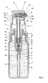
- einen Axialschnitt durch eine Saug-Druck-Pumpe mit einem erfindungsgemäßen Betätigungskopf auf einem mit einem auszugebenden Produkt gefüllten Behältnis vor der erstmaligen Betätigung der Saug-Druck-Pumpe mittels des Betätigungskopfes,
- Fig. 2
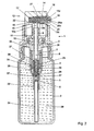
- einen Axialschnitt durch die Saug-Druck-Pumpe und das Behältnis nach Fig. 1 während einer erstmaligen Betätigung der Saug-Druck-Pumpe mittels des Betätigungskopfes,
- Fig. 3
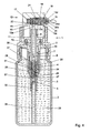
- einen Axialschnitt durch die Saug-Druck-Pumpe und das Behältnis nach Fig. 1 am Ende des ersten Saughubs der Saug-Druck-Pumpe,
- Fig. 4
- den gleichen Axialschnitt wie den nach Fig. 2 während einer erstmaligen Ausgabebetätigung und
- Fig. 5
- einen Axialschnitt durch die Saug-Druck-Pumpe in der gleichen Lage wie die nach Fig. 1, jedoch am Ende einer Ausgabebetätigung.
- Die dargestellte Saug-Druck-Pumpe 1 ist auf dem Rand der Öffnung eines Behältnisses 2 über eine dazwischen angeordnete Dichtringscheibe 3 dicht befestigt. Die Saug-Druck-Pumpe 1 hat ein hohlzylindrisches Gehäuse 4. Das untere Ende des Gehäuses 4 ist durch ein Rückschlagventil mit einer Ventilverschlußkugel 5 absperrbar. Die Ventilverschlußkugel 5 sitzt in ihrer in Fig. 1 dargestellten unteren Lage auf einem Ventilsitz 6 dicht auf.
- In dem Gehäuse 4 ist ein hohlzylindrischer Kolben 7, gegen die Innenseite des Gehäuses 4 dichtend, axial verschiebbar gelagert. Die Bohrung 8 des Kolbens 7 setzt sich in einer am Kolben 7 angeformten, hohlen Kolbenstange 9 fort. Die Kolbenstange 9 ist in einer Öffnung 10 einer oberen Verschlußhaube 11 von Gehäuse 4 und Behälter 2 abgedichtet verschiebbar.
- Auf dem freien Ende der aus dem Gehäuse 4 herausragenden Kolbenstange 9 ist ein Betätigungskopf 12 der Saug-Druck-Pumpe 1 dicht und fest aufgesetzt. Den Betätigungskopf 12 durchsetzt ein Auslaßkanal, bestehend aus Auslaßkanalabschnitten 13a-13d, der sich an die Bohrung 8 anschließt. Der Auslaßkanalabschnitt 13b ist als Ringraum ausgebildet, der durch die Innenseite einer Bohrung 14 im Körper des Betätigungskopfes 12 und die Außenseite eines in die Bohrung 14 fest eingesetzten Rohres 15 begrenzt ist. Der Auslaßkanalabschnitt 13c ist eine durch die Wand des Rohres 15 hindurchgehende Bohrung, die in den den Innenraum des Rohres 15 bildenden Auslaßkanalabschnitt 13d mündet. Das Rohr 15 verjüngt sich zu seinem äußeren Ende hin zu einer Ausspritzöffnung 16. In dem Auslaßkanalabschnitt 13d ist ein durch eine schwache Feder 17 belastetes Verschlußstück 18 axial verschiebbar angeordnet. Das Verschlußstück 18 hat einen gegen die Innenseite des Auslaßkanalabschnitts 13d in dem Rohr 15 dichtenden Kolben 19 mit einer Kolbenstange 20, die in der in Fig. 1 dargestellten Schließstellung des Verschlußstücks 18 mit einem Endabschnitt 20a dicht in die Ausspritzöffnung 16 ragt. Der an den Endabschnitt 20a angrenzende Abschnitt 20b der Kolbenstange 20 hat einen größeren Durchmesser als die Austrittsöffnung 16 und liegt in der Schließstellung des Verschlußstücks 18 mit einem schrägen Übergang vom größeren zum kleineren Durchmesser am inneren Rand der Ausspritzöffnung 16 unter der Kraft der Feder 17 an. Der Kolben 19 hat eine umlaufende Dichtlippe 21, die unter ihrer Eigenelastizität an der Innenseite des Rohres 15 bzw. des Auslaßkanalabschnitts 13d dicht anliegt und einen Durchtritt eines Mediums nur in Richtung zur Ausspritzöffnung 16 zuläßt, dagegen zu der die Feder 17 aufweisenden Kammer 22 sperrt. Die Dichtlippe 21 ist durch eine Topfmanschette gebildet. Das Verschlußstück 18 besteht aus gummielastischem Material, insbesondere einem Elastomer-Kunststoff mit einem Übermaß des Endabschnitts 20a der Kolbenstange 20 gegenüber dem Durchmesser der Ausspritzöffnung 16.
- Der Kolben 7 liegt in seiner unbetätigten Lage nach den Fig. 1, 3 und 5 mit einer an seinem freien Ende umlaufenden Dichtlippe 24 dicht an der Innenseite des Gehäuses 4 an. Ein den Kolben 7 oberhalb der Dichtlippe 24 umgebender Bund 25 dient der Führung des Kolbens 7 während seiner Bewegung, läßt jedoch ein Spiel zwischen sich und der Innenseite des Gehäuses 4 frei. Eine Rückstellfeder 26, die unterbrochen dargestellt ist, stützt sich einerseits im Kolben 7 am Boden eines Ringraums 27, der von der äußeren Wand des Kolbens 7 und einem Rohrstutzen 28 begrenzt ist, und andererseits an einer Schulter 29 im Gehäuse 4 ab. Das Gehäuse hat am Ende eines durch das Gehäuse 4 begrenzten Druckraums 30 eine Abstufung 31, unterhalb der der Innendurchmesser des Gehäuses 4 etwas größer als der Außendurchmesser der Dichtlippe 24 des Kolbens 7 ist. In einem Anschlußstutzen 32 am freien unteren Ende des Gehäuses 4 ist ein bis nahe an den Boden des Behältnisses 2 ragendes Tauchrohr 34 befestigt. Oberhalb der oberen Endlage des Kolbens 7 gemäß Fig. 1 ist das Gehäuse 4 durch seitliche Schlitze 35 mit dem Innenraum des Behältnisses 2 oberhalb des maximalen Produkt-Füllstandes verbunden.
- Bei der erstmaligen Betätigung des Betätigungskopfes 12 durch manuelle Ausübung eines Drucks auf seine Oberseite bewegt sich der Kolben 7 gegen die Kraft der Rückstellfeder 26 in dem Raum 30 gemäß Fig. 2 in Richtung auf das Rückschlagventil 5, 6. Durch den dabei im Raum 30, in der Bohrung 8 und im Auslaßkanal 13a-13d entstehenden Druck wird einerseits das Rückschlagventil 5, 6 geschlossen gehalten und andererseits die Dichtlippe 21 des Verschlußstücks 18 an die Innenseite des Rohres 15 bzw. des durch sie begrenzten Auslaßkanalabschnitts 13d gedrückt. Infolgedessen wird der Kolben 19 gegen die Kraft der Feder 17 verschoben und der Endabschnitt 20a der Kolbenstange 20 aus der Ausspritzöffnung 16 herausgezogen. Dabei kann die im Raum 30, in der Bohrung 8, im Auslaßkanal 13a-13d und in der Federkammer 22 enthaltene Luft teilweise durch die Ausspritzöffnung 16 austreten. Nach Wegnahme des manuellen Drucks vom Betätigungskopf 12 drückt die Rückstellfeder 26 den Kolben 7 und die Feder 17 den Kolben 19 in die in Fig. 3 dargestellte Lage zurück. Durch den dabei im Raum 30, in der Bohrung 8 und im Auslaßkanal 13a-13d entstehenden Unterdruck wird die Ventilverschlußkugel 5 bis gegen über ihr im Gehäuse 4 ausgebildete Rippen 37 von ihrem Sitz 6 abgehoben. Gleichzeitig wird durch den Unterdruck aus dem Behältnis 2 ein Teil des im Behältnis 2 enthaltenen Produkts 38 über das Tauchrohr 34 und das geöffnete Rückschlagventil 5, 6 bis in den Raum 30 gesaugt, wie es in Fig. 3 dargestellt ist. Das Produkt 38 ist vorzugsweise pastenartig, kann aber auch eine Flüssigkeit sein.
- Durch erneutes Niederdrücken des Kolbens 7 mittels des Betätigungskopfes 12 wird das Rückschlagventil 5, 6 wieder geschlossen und der Kolben 19 wieder gegen die Kraft der Feder 17 in die in Fig. 2 dargestellte Lage gedrückt. Gleichzeitig wird das Produkt aus dem Raum 30 über die Bohrung 8, den Auslaßkanal 13a-13d und die wieder geöffnete Ausspritzöffnung 16 ausgestoßen, wie es in Fig. 4 dargestellt ist. Dabei kann der Kolben 7 mit seiner Dichtlippe 24 bis unter die Abstufung 31 gedrückt werden. Sobald die Dichtlippe 24 dabei die Abstufung 31 überquert hat, wird der Druck im Raum 30 an der Dichtlippe 24 und dem Bund 25 des Kolbens 7 vorbei durch die Schlitze 35 in den Raum des Behältnisses 2 oberhalb des Produkt-Füllstandes abgebaut, so daß kein weiteres Produkt 38 mehr ausgestoßen wird. Dadurch wird die bei jeder Betätigung ausgegebene Produktmenge genau dosiert.
- Während der sich nach Wegnahme des manuellen Drucks auf den Betätigungskopf 12 anschließenden Rückbewegung des Kolbens 7 saugt der Kolben 7 erneut einen Teil des Produkts 38 aus dem Behältnis 2 in den Raum 30, wobei der Kolben 19 wieder die Ausspritzöffnung 16 unter dem Druck der Feder 17 schließt, wie es in Fig. 5 dargestellt ist.
- Wenn der Kolben 7 aus der Lage nach Fig. 5 erneut in die Lage nach Fig. 4 niedergedrückt wird, wird sofort wieder eine genau dosierte Produktmenge ausgegeben. Das gleiche geschieht bei jeder weiteren Betätigung bis zur völligen Entleerung des Behältnisses 2.
- Wie die Fig. 1, 3 und 5 zeigen, ist der Auslaßkanal 13a-13d in der Schließstellung des Verschlußstücks 18 nach außen hin völlig durch das Verschlußstück 18 abgesperrt. Ein im Auslaßkanal verbliebener Produktrest kann daher nicht mit schädlichen Keimen, Bakterien, Viren usw. sowie mit schädlichen Materien, Gasen usw. in Berührung kommen. Die Offenstellung des Verschlußstücks 18 nach den Fig. 2 und 4 dauert dagegen nur kurzzeitig an. Ein im Auslaßkanal 13a-13d verbliebener Produktrest würde dagegen bei der Produktausgabe weitgehend ausgestoßen und könnte nicht kontaminiert werden, da die Offenstellung des Verschlußstücks 18 nur kurzzeitig andauert.
- Das Verschlußstück 18 wirkt nicht nur als solches, sondern auch als Druckkolben, der das nach der Betätigung des Betätigungskopfes 12 im Abschnitt 13d des Auslaßkanals verbliebene Produkt unter der Kraft der Feder 17 durch die Ausspritzöffnung 16 ausspritzt und dabei gleichzeitig die Ausspritzöffnung 16 absperrt. Der den größeren Durchmesser aufweisende Abschnitt 20b der Kolbenstange 20 legt sich dabei während der Schließbewegung des Verschlußstücks 18 unter der Kraft der Feder 17 mit seiner vom größeren zum kleineren Durchmesser übergehenden Schulterfläche zusätzlich abdichtend am inneren Rand der Ausspritzöffnung 16 an. Gleichzeitig wird dadurch die Schließbewegung des Verschlußstücks 18 begrenzt.
- Die Dichtlippe 21 ermöglicht einerseits den Durchtritt von Luft aus der Federkammer 22 in den Auslaßkanal bei der erstmaligen Betätigung des Betätigungskopfes 12 und einer dadurch bedingten Verschiebung des Kolbens 19 gegen die Kraft der Feder 17. Daher ist im wesentlichen nur die Kraft der Feder 17 durch den Produktdruck während der Produktausgabe zu überwinden. Die dabei aus der Federkammer 22 in den Auslaßkanal eingedrungene Luft würde sich bei der erstmaligen Betätigung dann zwar teilweise mit der ausgegebenen und bei der nächsten Betätigung auszugebenden Produktmenge vermischen. Bei der zweiten und jeder folgenden Betätigung würde jedoch keine weitere Luft aus der Federkammer 22 in den Auslaßkanal gelangen, weil ihr Überdruck bereits abgebaut ist und die Dichtlippe 21 den Durchtritt der Luft nur in der einen Richtung und damit kein erneutes Eindringen von Luft in die Federkammer 22 zuläßt. Desgleichen wird auch ein Eindringen des Produkts über die Dichtlippe 21 hinweg in die Federkammer 22 verhindert. Da die Dichtlippe als Topfmanschette ausgebildet ist, wird sie durch den Produktdruck zusätzlich gegen die Innenseite des Rohres 15 bzw. des Abschnitts 13d des Auslaßkanals gedrückt. Sie sorgt daher für eine besonders hohe Dichtwirkung. Aufgrund der Ausbildung des Verschlußstücks 18 aus gummielastischem Material und mit einem Übermaß seines Endabschnitts 20a gegenüber dem Innendurchmesser der Ausspritzöffnung 16 legt sich der Endabschnitt 20a in der Schließstellung des Verschlußstücks 18 besonders fest in der Ausspritzöffnung 16 an. Dies ergibt eine besonders hohe Dichtwirkung des Endabschnitts 20a in der Ausspritzöffnung 16. Eine Ausbildung des gummielastischen Materials des Verschlußstücks 18 aus Kunststoff ermöglicht darüber hinaus eine einfache Herstellung des Verschlußstücks 18 als einstückiges Teil.
Claims (6)
- Betätigungskopf (12) einer Saug-Druck-Pumpe (1) zum Ausspritzen eines Produkts (38) aus einem Behältnis (2), der einen zu einer Ausspritzöffnung (16) führenden Auslaßkanal (13a-13d) aufweist, in dem ein durch eine Feder (17) belastetes Verschlußstück (18) angeordnet ist, wobei das Verschlußstück (18) in seiner Schließstellung die Ausspritzöffnung (16) unter der Kraft der Feder (17) unmittelbar abdichtet und den bei Betätigung der Saug-Druck-Pumpe (1) ausgeübten Druck des Produkts (38) dessen Durchfluß durch den Auslaßkanal (13a-13d) und durch die Ausspritzöffnung (16) gegen die Kraft der Feder (17) freigibt, wobei ein sich an die Ausspritzöffnung (16) anschließender erster Auslaßkanalabschnitt (13d) von einem Rohr (15) umgeben ist, in dem das Verschlußstück (18) abgedichtet verschiebbar geführt ist und das in eine Bohrung (14) im Körper des Betätigungskopfes (12) eingesetzt ist, die zwischen sich und dem Rohr (15) einen einen zweiten Auslaßkanalabschnitt (13b) bildenden Ringraum begrenzt, der über einen dritten, die Wand des Rohres (15) durchquerenden Auslaßkanalabschnitt (13c) mit dem ersten Auslaßkanalabschnitt (13d) verbunden ist, dadurch gekennzeichnet, daß das Verschlußstück (18) aus gummielastischem Material mit einem Übermaß des Endabschnitts (20a) gegenüber dem Durchmesser der Ausspritzöffnung (16) besteht.
- Betätigungskopf nach Anspruch 1, dadurch gekennzeichnet, daß das Verschlußstück (18) einen gegen die Innenseite des Auslaßkanals (13a-13d) dichtenden Kolben (19) mit einer Kolbenstange (20) aufweist, die in der Schließstellung des Verschlußstücks (18) mit einem Endabschnitt (20a) dicht in die Ausspritzöffnung (16) ragt.
- Betätigungskopf nach Anspruch 2, dadurch gekennzeichnet, daß der an den Endabschnitt (20a) angrenzende Abschnitt (20b) der Kolbenstange (20) einen größeren Durchmesser als die Ausspritzöffnung (16) hat und in der Schließstellung des Verschlußstücks (18) am inneren Rand der Ausspritzöffnung (16) unter der Kraft der Feder (17) anliegt.
- Betätigungskopf nach Anspruch 2 oder 3, dadurch gekennzeichnet, daß der Kolben (19) eine umlaufende Dichtlippe (21) aufweist, die einen Durchtritt eines Mediums nur in Richtung zur Ausspritzöffnung (16) zuläßt.
- Betätigungskopf nach Anspruch 4, dadurch gekennzeichnet, daß die Dichtlippe (21) durch eine Topfmanschette gebildet ist.
- Betätigungskopf nach einem der Ansprüche 1 bis 5, dadurch gekennzeichnet, daß das gummielastische Material ein Kunststoff ist.
Applications Claiming Priority (2)
| Application Number | Priority Date | Filing Date | Title |
|---|---|---|---|
| DE10200593A DE10200593A1 (de) | 2002-01-10 | 2002-01-10 | Betätigungskopf einer Saug-Druck-Pumpe zum Ausspritzen eines Produkts aus einem Behältnis |
| DE10200593 | 2002-01-10 |
Publications (2)
| Publication Number | Publication Date |
|---|---|
| EP1327478A1 EP1327478A1 (de) | 2003-07-16 |
| EP1327478B1 true EP1327478B1 (de) | 2007-08-29 |
Family
ID=7711770
Family Applications (1)
| Application Number | Title | Priority Date | Filing Date |
|---|---|---|---|
| EP03000259A Expired - Lifetime EP1327478B1 (de) | 2002-01-10 | 2003-01-08 | Betätigungskopf einer Saug-Druck-Pumpe zum Ausspritzen eines Produkts aus einem Behältnis |
Country Status (6)
| Country | Link |
|---|---|
| US (1) | US6824021B2 (de) |
| EP (1) | EP1327478B1 (de) |
| AT (1) | ATE371502T1 (de) |
| DE (2) | DE10200593A1 (de) |
| DK (1) | DK1327478T3 (de) |
| ES (1) | ES2289187T3 (de) |
Cited By (8)
| Publication number | Priority date | Publication date | Assignee | Title |
|---|---|---|---|---|
| US8225966B2 (en) | 2006-03-15 | 2012-07-24 | Seaquist Perfect Dispensing Gmbh | Dispensing device |
| US8240518B2 (en) | 2006-05-16 | 2012-08-14 | Seaquist Perfect Dispensing Gmbh | Dispensing device and container for a cosmetic liquid |
| US8286839B2 (en) | 2008-08-12 | 2012-10-16 | Aptar Dortmund Gmbh | Dispensing device |
| US8453875B2 (en) | 2008-06-20 | 2013-06-04 | Aptar Dortmund Gmbh | Dispensing device |
| US8573449B2 (en) | 2006-06-08 | 2013-11-05 | Aptar Dortmund Gmbh | Dispensing device having an elastically deformable section for pumping a fluid |
| US8616416B2 (en) | 2008-08-12 | 2013-12-31 | Aptar Dortmund Gmbh | Delivery head |
| US8616417B2 (en) | 2009-06-25 | 2013-12-31 | Aptar Dortmund Gmbh | Valve and discharge device |
| US8863994B2 (en) | 2007-03-15 | 2014-10-21 | Aptar Dortmund Gmbh | Dispensing device |
Families Citing this family (20)
| Publication number | Priority date | Publication date | Assignee | Title |
|---|---|---|---|---|
| AU2003226934A1 (en) * | 2002-04-10 | 2003-10-27 | Disop-Nordic Holding Aps | Tube with self-closing mechanism for liquid container |
| DE10323603A1 (de) | 2003-05-20 | 2004-12-30 | Ing. Erich Pfeiffer Gmbh | Dosiervorrichtung mit einer Pumpeinrichtung |
| WO2005070560A1 (fr) * | 2003-12-22 | 2005-08-04 | Valois Sas | Organe de distribution de produit fluide et distributeur comprenant un tel organe |
| DE102005031325A1 (de) * | 2005-07-05 | 2007-01-11 | Katz, Otto, Dipl.-Ing. | Cremespender |
| JP4650848B2 (ja) * | 2006-01-26 | 2011-03-16 | 株式会社三谷バルブ | ポンプ式容器の内容物放出機構および内容物放出機構を備えたポンプ式製品 |
| US20070221686A1 (en) * | 2006-03-27 | 2007-09-27 | Taesung Industrial Co., Ltd. | Liquid pump dispenser |
| EP2099572B1 (de) * | 2006-09-07 | 2014-07-23 | Aptar Dortmund GmbH | Abgabevorrichtung |
| FR2922528B1 (fr) * | 2007-10-23 | 2010-03-26 | Rexam Dispensing Smt | Pompe de distribution d'un liquide contenu dans un flacon |
| DE102008027987A1 (de) | 2008-03-04 | 2009-09-17 | Kist-Europe Forschungsgesellschaft Mbh | Dosierungsvorrichtung |
| JP5413895B2 (ja) * | 2008-10-31 | 2014-02-12 | 株式会社吉野工業所 | ポンプの押下げヘッド及び押下げヘッド式吐出ポンプ |
| KR101025191B1 (ko) * | 2009-03-03 | 2011-04-01 | (주)톨리코리아 | 화장품용기의 노즐개폐장치 |
| CN102421684A (zh) * | 2009-03-19 | 2012-04-18 | 卢姆森股份公司 | 用于流体物质的分配装置 |
| FR2976981B1 (fr) * | 2011-06-27 | 2013-07-05 | Promens Sa | Systeme de fermeture d'un dispositif de distribution a basse pression d'un produit liquide a pateux |
| DE102013202531B3 (de) * | 2013-02-16 | 2014-05-28 | Aptar Radolfzell Gmbh | Spender zum Austrag von Flüssigkeiten |
| DE102013113791A1 (de) * | 2013-12-10 | 2015-06-11 | Rpc Bramlage Gmbh | Spender |
| FR3015443B1 (fr) * | 2013-12-23 | 2016-07-01 | Lablabo | Dispositif de conditionnement et de distribution de produits fluides, liquides ou pateux |
| DE102016204953A1 (de) * | 2016-03-24 | 2017-09-28 | F. Holzer Gmbh | Dosierpumpe für eine Dosiervorrichtung sowie Dosiervorrichtung |
| KR102609420B1 (ko) * | 2021-07-30 | 2023-12-04 | 펌텍코리아 (주) | 액상 내용물 토출 용기 |
| CN116603658A (zh) * | 2023-06-16 | 2023-08-18 | 精英模具制品(上海)有限公司 | 一种自封闭按压盖 |
| EP4497508A1 (de) * | 2023-07-27 | 2025-01-29 | Aero Pump GmbH | Abgabevorrichtung für ein fluid |
Family Cites Families (21)
| Publication number | Priority date | Publication date | Assignee | Title |
|---|---|---|---|---|
| NL273959A (de) | 1961-01-27 | |||
| NL152462B (nl) * | 1969-12-08 | 1977-03-15 | Diamonat Limited | Verstuivingspomp. |
| GB1586170A (en) | 1976-10-01 | 1981-03-18 | Aero Pump Gmbh | Device for spraying a liquid from a closed container |
| DE3001687C2 (de) | 1980-01-18 | 1981-09-17 | Kläger, Karlheinz, 8901 Neusäß | Verstellbare Düse an einem handbetätigten Flüssigkeitszerstäuber |
| US4558821A (en) | 1983-03-03 | 1985-12-17 | Canyon Corporation | Trigger-type sprayer with integrally formed housing, trigger, nozzle and cylinder |
| FR2622478B1 (fr) | 1987-11-03 | 1990-03-30 | Valois | Gicleur pour vaporisateur du type valve pour aerosols |
| FR2635084B1 (fr) | 1988-08-08 | 1991-04-12 | Sofab | Embouts de distributeurs |
| DE68902989T2 (de) | 1988-12-20 | 1993-04-15 | Step Soc Tech Pulverisation | Vorrichtung zum spenden einer fluessigkeit oder einer creme in tropfen kleinen volumens. |
| FR2654078B1 (fr) | 1989-11-07 | 1992-02-28 | Valois | Obturateur du canal de sortie d'une tete de distribution pour produits pateux et tete de distribution avantageusement associee. |
| FR2665848B1 (fr) | 1990-08-17 | 1992-10-30 | Aerosols & Bouchage | Buses a clapet incorpore. |
| FR2674747B1 (fr) * | 1991-04-05 | 1993-07-30 | Step Soc Tech Pulverisation | Dispositif distributeur de gouttes de petit volume, notamment pour soins ophtalmologiques. |
| US5273191A (en) * | 1991-08-20 | 1993-12-28 | Philip Meshberg | Dispensing head for a squeeze dispenser |
| FR2705589B1 (fr) | 1993-05-28 | 1995-07-28 | Valois | Buse de pulvérisation et pulvérisateur comportant une telle buse. |
| IT1270138B (it) * | 1994-05-25 | 1997-04-29 | Giovanni Albini | Erogatore di fluidi in pressione nebulizzati , provvisto do otturatore mobile per azione del fluido in pressione |
| FR2746657B1 (fr) | 1996-03-29 | 1998-06-26 | Sofab | Dispositif antibacterien de pulverisation d'un produit liquide |
| WO1998014279A1 (en) * | 1996-10-03 | 1998-04-09 | Pentel Kabushiki Kaisha | Blow-out container |
| DE19742559C2 (de) * | 1997-09-26 | 1999-08-05 | Gaplast Gmbh | Behälter mit Pumpe |
| FR2773784B1 (fr) * | 1998-01-16 | 2000-03-24 | Valois Sa | Tete de pulverisation pour un distributeur de produit fluide |
| DE29811242U1 (de) * | 1998-06-24 | 1999-11-04 | Fritz Albert Riegler GmbH & Co. KG, 64367 Mühltal | Applikations-Vorrichtung für keimfreie Fluide |
| DE20103144U1 (de) * | 2001-02-22 | 2001-06-13 | Padar, Steven, 65779 Kelkheim | Abgabevorrichtung für Fluide |
| DE20103514U1 (de) | 2001-02-28 | 2001-05-10 | H & G GmbH, 95189 Köditz | Kompensator-Textil und damit hergestellter Kompensator |
-
2002
- 2002-01-10 DE DE10200593A patent/DE10200593A1/de not_active Withdrawn
-
2003
- 2003-01-08 DK DK03000259T patent/DK1327478T3/da active
- 2003-01-08 AT AT03000259T patent/ATE371502T1/de active
- 2003-01-08 DE DE50308038T patent/DE50308038D1/de not_active Expired - Lifetime
- 2003-01-08 EP EP03000259A patent/EP1327478B1/de not_active Expired - Lifetime
- 2003-01-08 ES ES03000259T patent/ES2289187T3/es not_active Expired - Lifetime
- 2003-01-10 US US10/340,873 patent/US6824021B2/en not_active Expired - Lifetime
Cited By (11)
| Publication number | Priority date | Publication date | Assignee | Title |
|---|---|---|---|---|
| US8225966B2 (en) | 2006-03-15 | 2012-07-24 | Seaquist Perfect Dispensing Gmbh | Dispensing device |
| US8602266B2 (en) | 2006-03-15 | 2013-12-10 | Aptar Dortmund Gmbh | Dispensing device |
| US9205437B2 (en) | 2006-03-15 | 2015-12-08 | Aptar Dortmund Gmbh | Dispensing device |
| US8240518B2 (en) | 2006-05-16 | 2012-08-14 | Seaquist Perfect Dispensing Gmbh | Dispensing device and container for a cosmetic liquid |
| US8573449B2 (en) | 2006-06-08 | 2013-11-05 | Aptar Dortmund Gmbh | Dispensing device having an elastically deformable section for pumping a fluid |
| US8863994B2 (en) | 2007-03-15 | 2014-10-21 | Aptar Dortmund Gmbh | Dispensing device |
| US8453875B2 (en) | 2008-06-20 | 2013-06-04 | Aptar Dortmund Gmbh | Dispensing device |
| US8678245B2 (en) | 2008-06-20 | 2014-03-25 | Aptar Dortmund Gmbh | Dispensing device |
| US8286839B2 (en) | 2008-08-12 | 2012-10-16 | Aptar Dortmund Gmbh | Dispensing device |
| US8616416B2 (en) | 2008-08-12 | 2013-12-31 | Aptar Dortmund Gmbh | Delivery head |
| US8616417B2 (en) | 2009-06-25 | 2013-12-31 | Aptar Dortmund Gmbh | Valve and discharge device |
Also Published As
| Publication number | Publication date |
|---|---|
| DE50308038D1 (de) | 2007-10-11 |
| DE10200593A1 (de) | 2003-07-31 |
| ES2289187T3 (es) | 2008-02-01 |
| ATE371502T1 (de) | 2007-09-15 |
| EP1327478A1 (de) | 2003-07-16 |
| US20030164385A1 (en) | 2003-09-04 |
| DK1327478T3 (da) | 2008-02-04 |
| US6824021B2 (en) | 2004-11-30 |
Similar Documents
| Publication | Publication Date | Title |
|---|---|---|
| EP1327478A1 (de) | Betätigungskopf einer Saug-Druck-Pumpe zum Ausspritzen eines Produkts aus einem Behältnis | |
| DE2901717C2 (de) | ||
| EP1380351B1 (de) | Spenderpumpe mit antibakterieller Vorrichtung | |
| DE3425478C2 (de) | ||
| DE69803361T2 (de) | Vorrichtung zur abgabe vom fliessfähigen produkt mit verschlussvorrichtung | |
| DE19729516C2 (de) | Pumpe zum dosierten Austragen von flüssigen, gelartigen oder viskosen Substanzen | |
| DE3586780T2 (de) | Pumpe zur verteilung einer fluessigkeit aus einem behaelter. | |
| EP2200752B1 (de) | Dosierungsvorrichtung | |
| EP0739247B1 (de) | Saug-druckpumpe für fluidbehälter | |
| EP1358944A2 (de) | Spender zum Austrag fliessfähiger Medien | |
| DE1653419A1 (de) | Fluessigkeitsabgabepumpe | |
| DE10231751B4 (de) | Saug-Druck-Pumpe zum Ausspritzen eines Produkts aus einem Behältnis | |
| DE2645089A1 (de) | Betaetigungsvorrichtung fuer einen ausgabemechanismus fuer fluessige, halbfluessige oder gasfoermige substanzen | |
| DE2001921A1 (de) | Hin- und herbewegte Fluessigkeitsabgabepumpe | |
| WO1985002563A1 (fr) | Pompe pulverisatrice avec raccord de recipient | |
| DE2818507A1 (de) | Handbetaetigte axialkolbenpumpe | |
| DE69821495T2 (de) | Handpumpe mit durch Plastikfedern beaufschlagtem Freikolben | |
| EP3359298B1 (de) | Spender für insbesondere flüssige bis pastöse massen | |
| DE102014200867A1 (de) | Spender für Flüssigkeiten | |
| DE20110604U1 (de) | Spender für pastöses Produkt | |
| EP2634112A1 (de) | Wiederbefüllbarer Ausgabebehälter | |
| DE2640837A1 (de) | Manuell betaetigbare pumpe | |
| DE602004005613T2 (de) | Pumpe zur abgabe eines fluidprodukts | |
| CH718212A1 (de) | Pumpspender. | |
| DE1027945B (de) | Abgabeventil |
Legal Events
| Date | Code | Title | Description |
|---|---|---|---|
| PUAI | Public reference made under article 153(3) epc to a published international application that has entered the european phase |
Free format text: ORIGINAL CODE: 0009012 |
|
| AK | Designated contracting states |
Designated state(s): AT BE BG CH CY CZ DE DK EE ES FI FR GB GR HU IE IT LI LU MC NL PT SE SI SK TR |
|
| AX | Request for extension of the european patent |
Extension state: AL LT LV MK RO |
|
| 17P | Request for examination filed |
Effective date: 20030522 |
|
| AKX | Designation fees paid |
Designated state(s): AT BE BG CH CY CZ DE DK EE ES FI FR GB GR HU IE IT LI LU MC NL PT SE SI SK TR |
|
| 17Q | First examination report despatched |
Effective date: 20061218 |
|
| GRAP | Despatch of communication of intention to grant a patent |
Free format text: ORIGINAL CODE: EPIDOSNIGR1 |
|
| GRAS | Grant fee paid |
Free format text: ORIGINAL CODE: EPIDOSNIGR3 |
|
| GRAA | (expected) grant |
Free format text: ORIGINAL CODE: 0009210 |
|
| AK | Designated contracting states |
Kind code of ref document: B1 Designated state(s): AT BE BG CH CY CZ DE DK EE ES FI FR GB GR HU IE IT LI LU MC NL PT SE SI SK TR |
|
| REG | Reference to a national code |
Ref country code: GB Ref legal event code: FG4D Free format text: NOT ENGLISH |
|
| REG | Reference to a national code |
Ref country code: CH Ref legal event code: EP |
|
| REG | Reference to a national code |
Ref country code: IE Ref legal event code: FG4D Free format text: LANGUAGE OF EP DOCUMENT: GERMAN |
|
| REF | Corresponds to: |
Ref document number: 50308038 Country of ref document: DE Date of ref document: 20071011 Kind code of ref document: P |
|
| REG | Reference to a national code |
Ref country code: CH Ref legal event code: NV Representative=s name: LUCHS & PARTNER PATENTANWAELTE |
|
| GBT | Gb: translation of ep patent filed (gb section 77(6)(a)/1977) |
Effective date: 20071008 |
|
| REG | Reference to a national code |
Ref country code: SE Ref legal event code: TRGR |
|
| PG25 | Lapsed in a contracting state [announced via postgrant information from national office to epo] |
Ref country code: NL Free format text: LAPSE BECAUSE OF FAILURE TO SUBMIT A TRANSLATION OF THE DESCRIPTION OR TO PAY THE FEE WITHIN THE PRESCRIBED TIME-LIMIT Effective date: 20070829 Ref country code: FI Free format text: LAPSE BECAUSE OF FAILURE TO SUBMIT A TRANSLATION OF THE DESCRIPTION OR TO PAY THE FEE WITHIN THE PRESCRIBED TIME-LIMIT Effective date: 20070829 |
|
| NLV1 | Nl: lapsed or annulled due to failure to fulfill the requirements of art. 29p and 29m of the patents act | ||
| REG | Reference to a national code |
Ref country code: ES Ref legal event code: FG2A Ref document number: 2289187 Country of ref document: ES Kind code of ref document: T3 |
|
| REG | Reference to a national code |
Ref country code: DK Ref legal event code: T3 |
|
| ET | Fr: translation filed | ||
| REG | Reference to a national code |
Ref country code: IE Ref legal event code: FD4D |
|
| PG25 | Lapsed in a contracting state [announced via postgrant information from national office to epo] |
Ref country code: GR Free format text: LAPSE BECAUSE OF FAILURE TO SUBMIT A TRANSLATION OF THE DESCRIPTION OR TO PAY THE FEE WITHIN THE PRESCRIBED TIME-LIMIT Effective date: 20071130 |
|
| PG25 | Lapsed in a contracting state [announced via postgrant information from national office to epo] |
Ref country code: CZ Free format text: LAPSE BECAUSE OF FAILURE TO SUBMIT A TRANSLATION OF THE DESCRIPTION OR TO PAY THE FEE WITHIN THE PRESCRIBED TIME-LIMIT Effective date: 20070829 Ref country code: IE Free format text: LAPSE BECAUSE OF FAILURE TO SUBMIT A TRANSLATION OF THE DESCRIPTION OR TO PAY THE FEE WITHIN THE PRESCRIBED TIME-LIMIT Effective date: 20070829 Ref country code: PT Free format text: LAPSE BECAUSE OF FAILURE TO SUBMIT A TRANSLATION OF THE DESCRIPTION OR TO PAY THE FEE WITHIN THE PRESCRIBED TIME-LIMIT Effective date: 20080129 Ref country code: SK Free format text: LAPSE BECAUSE OF FAILURE TO SUBMIT A TRANSLATION OF THE DESCRIPTION OR TO PAY THE FEE WITHIN THE PRESCRIBED TIME-LIMIT Effective date: 20070829 |
|
| PLBE | No opposition filed within time limit |
Free format text: ORIGINAL CODE: 0009261 |
|
| STAA | Information on the status of an ep patent application or granted ep patent |
Free format text: STATUS: NO OPPOSITION FILED WITHIN TIME LIMIT |
|
| BERE | Be: lapsed |
Owner name: AERO PUMP G.M.B.H. ZERSTAUBERPUMPEN Effective date: 20080131 |
|
| 26N | No opposition filed |
Effective date: 20080530 |
|
| PG25 | Lapsed in a contracting state [announced via postgrant information from national office to epo] |
Ref country code: MC Free format text: LAPSE BECAUSE OF NON-PAYMENT OF DUE FEES Effective date: 20080131 |
|
| PG25 | Lapsed in a contracting state [announced via postgrant information from national office to epo] |
Ref country code: EE Free format text: LAPSE BECAUSE OF FAILURE TO SUBMIT A TRANSLATION OF THE DESCRIPTION OR TO PAY THE FEE WITHIN THE PRESCRIBED TIME-LIMIT Effective date: 20070829 |
|
| PG25 | Lapsed in a contracting state [announced via postgrant information from national office to epo] |
Ref country code: BE Free format text: LAPSE BECAUSE OF NON-PAYMENT OF DUE FEES Effective date: 20080131 |
|
| PG25 | Lapsed in a contracting state [announced via postgrant information from national office to epo] |
Ref country code: SI Free format text: LAPSE BECAUSE OF FAILURE TO SUBMIT A TRANSLATION OF THE DESCRIPTION OR TO PAY THE FEE WITHIN THE PRESCRIBED TIME-LIMIT Effective date: 20070829 |
|
| PG25 | Lapsed in a contracting state [announced via postgrant information from national office to epo] |
Ref country code: CY Free format text: LAPSE BECAUSE OF FAILURE TO SUBMIT A TRANSLATION OF THE DESCRIPTION OR TO PAY THE FEE WITHIN THE PRESCRIBED TIME-LIMIT Effective date: 20070829 |
|
| PG25 | Lapsed in a contracting state [announced via postgrant information from national office to epo] |
Ref country code: BG Free format text: LAPSE BECAUSE OF FAILURE TO SUBMIT A TRANSLATION OF THE DESCRIPTION OR TO PAY THE FEE WITHIN THE PRESCRIBED TIME-LIMIT Effective date: 20071129 |
|
| PG25 | Lapsed in a contracting state [announced via postgrant information from national office to epo] |
Ref country code: HU Free format text: LAPSE BECAUSE OF FAILURE TO SUBMIT A TRANSLATION OF THE DESCRIPTION OR TO PAY THE FEE WITHIN THE PRESCRIBED TIME-LIMIT Effective date: 20080301 Ref country code: LU Free format text: LAPSE BECAUSE OF NON-PAYMENT OF DUE FEES Effective date: 20080108 |
|
| PG25 | Lapsed in a contracting state [announced via postgrant information from national office to epo] |
Ref country code: TR Free format text: LAPSE BECAUSE OF FAILURE TO SUBMIT A TRANSLATION OF THE DESCRIPTION OR TO PAY THE FEE WITHIN THE PRESCRIBED TIME-LIMIT Effective date: 20070829 |
|
| REG | Reference to a national code |
Ref country code: FR Ref legal event code: PLFP Year of fee payment: 13 |
|
| REG | Reference to a national code |
Ref country code: FR Ref legal event code: PLFP Year of fee payment: 14 |
|
| REG | Reference to a national code |
Ref country code: FR Ref legal event code: PLFP Year of fee payment: 15 |
|
| REG | Reference to a national code |
Ref country code: FR Ref legal event code: PLFP Year of fee payment: 16 |
|
| PGFP | Annual fee paid to national office [announced via postgrant information from national office to epo] |
Ref country code: GB Payment date: 20220125 Year of fee payment: 20 Ref country code: DK Payment date: 20220121 Year of fee payment: 20 Ref country code: DE Payment date: 20220126 Year of fee payment: 20 Ref country code: CH Payment date: 20220125 Year of fee payment: 20 Ref country code: AT Payment date: 20220119 Year of fee payment: 20 |
|
| PGFP | Annual fee paid to national office [announced via postgrant information from national office to epo] |
Ref country code: SE Payment date: 20220125 Year of fee payment: 20 Ref country code: IT Payment date: 20220124 Year of fee payment: 20 Ref country code: FR Payment date: 20220120 Year of fee payment: 20 Ref country code: ES Payment date: 20220216 Year of fee payment: 20 |
|
| REG | Reference to a national code |
Ref country code: DE Ref legal event code: R071 Ref document number: 50308038 Country of ref document: DE |
|
| REG | Reference to a national code |
Ref country code: DK Ref legal event code: EUP Expiry date: 20230108 |
|
| REG | Reference to a national code |
Ref country code: CH Ref legal event code: PL |
|
| REG | Reference to a national code |
Ref country code: GB Ref legal event code: PE20 Expiry date: 20230107 |
|
| REG | Reference to a national code |
Ref country code: AT Ref legal event code: MK07 Ref document number: 371502 Country of ref document: AT Kind code of ref document: T Effective date: 20230108 |
|
| REG | Reference to a national code |
Ref country code: SE Ref legal event code: EUG |
|
| REG | Reference to a national code |
Ref country code: ES Ref legal event code: FD2A Effective date: 20230426 |
|
| PG25 | Lapsed in a contracting state [announced via postgrant information from national office to epo] |
Ref country code: GB Free format text: LAPSE BECAUSE OF EXPIRATION OF PROTECTION Effective date: 20230107 |
|
| PG25 | Lapsed in a contracting state [announced via postgrant information from national office to epo] |
Ref country code: ES Free format text: LAPSE BECAUSE OF EXPIRATION OF PROTECTION Effective date: 20230109 |