EP1327460B1 - Dispositif d'introduction multi-cathéter - Google Patents
Dispositif d'introduction multi-cathéter Download PDFInfo
- Publication number
- EP1327460B1 EP1327460B1 EP03250185A EP03250185A EP1327460B1 EP 1327460 B1 EP1327460 B1 EP 1327460B1 EP 03250185 A EP03250185 A EP 03250185A EP 03250185 A EP03250185 A EP 03250185A EP 1327460 B1 EP1327460 B1 EP 1327460B1
- Authority
- EP
- European Patent Office
- Prior art keywords
- catheter
- shunt device
- secondary catheters
- primary catheter
- catheters
- Prior art date
- Legal status (The legal status is an assumption and is not a legal conclusion. Google has not performed a legal analysis and makes no representation as to the accuracy of the status listed.)
- Expired - Lifetime
Links
Images


Classifications
-
- A—HUMAN NECESSITIES
- A61—MEDICAL OR VETERINARY SCIENCE; HYGIENE
- A61M—DEVICES FOR INTRODUCING MEDIA INTO, OR ONTO, THE BODY; DEVICES FOR TRANSDUCING BODY MEDIA OR FOR TAKING MEDIA FROM THE BODY; DEVICES FOR PRODUCING OR ENDING SLEEP OR STUPOR
- A61M27/00—Drainage appliance for wounds or the like, i.e. wound drains, implanted drains
- A61M27/002—Implant devices for drainage of body fluids from one part of the body to another
- A61M27/006—Cerebrospinal drainage; Accessories therefor, e.g. valves
-
- A—HUMAN NECESSITIES
- A61—MEDICAL OR VETERINARY SCIENCE; HYGIENE
- A61M—DEVICES FOR INTRODUCING MEDIA INTO, OR ONTO, THE BODY; DEVICES FOR TRANSDUCING BODY MEDIA OR FOR TAKING MEDIA FROM THE BODY; DEVICES FOR PRODUCING OR ENDING SLEEP OR STUPOR
- A61M25/00—Catheters; Hollow probes
- A61M25/01—Introducing, guiding, advancing, emplacing or holding catheters
- A61M25/06—Body-piercing guide needles or the like
- A61M25/0662—Guide tubes
-
- A—HUMAN NECESSITIES
- A61—MEDICAL OR VETERINARY SCIENCE; HYGIENE
- A61M—DEVICES FOR INTRODUCING MEDIA INTO, OR ONTO, THE BODY; DEVICES FOR TRANSDUCING BODY MEDIA OR FOR TAKING MEDIA FROM THE BODY; DEVICES FOR PRODUCING OR ENDING SLEEP OR STUPOR
- A61M27/00—Drainage appliance for wounds or the like, i.e. wound drains, implanted drains
- A61M27/002—Implant devices for drainage of body fluids from one part of the body to another
-
- A—HUMAN NECESSITIES
- A61—MEDICAL OR VETERINARY SCIENCE; HYGIENE
- A61M—DEVICES FOR INTRODUCING MEDIA INTO, OR ONTO, THE BODY; DEVICES FOR TRANSDUCING BODY MEDIA OR FOR TAKING MEDIA FROM THE BODY; DEVICES FOR PRODUCING OR ENDING SLEEP OR STUPOR
- A61M25/00—Catheters; Hollow probes
- A61M25/0021—Catheters; Hollow probes characterised by the form of the tubing
- A61M2025/0042—Microcatheters, cannula or the like having outside diameters around 1 mm or less
-
- A—HUMAN NECESSITIES
- A61—MEDICAL OR VETERINARY SCIENCE; HYGIENE
- A61M—DEVICES FOR INTRODUCING MEDIA INTO, OR ONTO, THE BODY; DEVICES FOR TRANSDUCING BODY MEDIA OR FOR TAKING MEDIA FROM THE BODY; DEVICES FOR PRODUCING OR ENDING SLEEP OR STUPOR
- A61M25/00—Catheters; Hollow probes
- A61M25/01—Introducing, guiding, advancing, emplacing or holding catheters
- A61M25/06—Body-piercing guide needles or the like
- A61M25/0662—Guide tubes
- A61M2025/0681—Systems with catheter and outer tubing, e.g. sheath, sleeve or guide tube
-
- A—HUMAN NECESSITIES
- A61—MEDICAL OR VETERINARY SCIENCE; HYGIENE
- A61M—DEVICES FOR INTRODUCING MEDIA INTO, OR ONTO, THE BODY; DEVICES FOR TRANSDUCING BODY MEDIA OR FOR TAKING MEDIA FROM THE BODY; DEVICES FOR PRODUCING OR ENDING SLEEP OR STUPOR
- A61M2210/00—Anatomical parts of the body
- A61M2210/06—Head
- A61M2210/0693—Brain, cerebrum
Definitions
- the present invention relates to a catheter device and method useful with a shunt system, and in particular to a multi-catheter shunt device that minimizes the risk of blockage or obstruction or the catheter pores.
- Hydrocephalus is a neurological condition that is caused by the abnormal accumulation of cerebrospinal fluid (CSF) within the ventricles, or cavities, of the brain.
- CSF cerebrospinal fluid
- CSF is a clear, colorless fluid that is primarily produced by the choroid plexus and surrounds the brain and spinal cord.
- CSF constantly circulates through the ventricular system of the brain and is ultimately absorbed into the bloodstream.
- CSF aids in the protection of the brain and spinal cord.
- the fluid barrier between the CSF and the blood prevents harmful substances from flowing from the capillaries into the CSF.
- Hydrocephalus which can affect people of any age, but affects mostly infants and young children, arises when the normal drainage of CSF in the brain is blocked in some way.
- Such blockage can be caused by a number of factors, including, for example, genetic predisposition, intraventricular or intracranial hemorrhage, infections such as meningitis, head trauma, or the like.
- Blockage of the flow of CSF requires an increasing pressure for CSF to be absorbed into the bloodstream. This increasing pressure can interfere with the perfusion of the nervous system.
- Hydrocephalus is most often treated by surgically inserting a shunt system that diverts the flow of CSF from the ventricle to another area of the body where the CSF can be absorbed as part of the circulatory system.
- Shunt systems come in a variety of models, and typically share similar functional components. These components include a ventricular catheter which is introduced through a burr hole in the skull and implanted in the patient's ventricle, a drainage catheter that carries the CSF to its ultimate drainage site, and optionally a flow-control mechanism, e.g., shunt valve, that regulates the one-way flow of CSF from the ventricle to the drainage site to maintain normal pressure within the ventricles.
- a flow-control mechanism e.g., shunt valve
- the ventricular catheter typically contains multiple holes or pores positioned along the length of the ventricular catheter to allow the CSF to enter into the shunt system.
- a removable rigid stylet situated within the lumen of the ventricular catheter, is used to direct the catheter toward the desired targeted location.
- blunt tip brain cannulas and peel-away sheaths have been used to aid placement of the catheters.
- Shunting is considered one of the basic neurosurgical procedures, yet it has the highest complication rate.
- the most common complication with shunting is obstruction of the system. Although obstruction or clogging may occur at any point along the shunt system, it most frequently occurs at the ventricular end of the shunt system. While there are several ways that the ventricular catheter may become blocked or clogged, obstruction is typically caused by growth of tissue, such as the choroid plexus, around the catheter and into the pores. The pores of the ventricular catheter can also be obstructed by debris, bacteria, or blood clogged in the pores of the catheter. Additionally, problems with the ventricular catheter can arise from overdrainage of the CSF, which can cause the ventricle walls to collapse upon the catheter and block the pores in the catheter wall, thereby preventing CSF drainage.
- backflushing is a process that uses the CSF present in the shunt system to remove the obstructing matter. This process can be ineffective, however, due to the small size of the pores of the ventricular catheter and due to the small amount of flushing liquid available in the shunt system.
- Other shunt systems have been designed to include a mechanism for flushing the shunt system.
- some shunt systems include a pumping device within the system which causes fluid in the system to flow with considerable pressure and velocity, thereby flushing the system.
- using a built-in mechanism to flush the shunt system can also fail to remove the obstruction due to factors such as the size of the pores and the degree and extent to which the pores have been clogged.
- Occluded ventricular catheters can also be repaired by cauterizing the catheter to reopen existing pores, or optionally to create additional pores. These repairs, however, may be incapable of removing obstructions from the ventricular catheter depending on the location of the clogged pores. Additionally, the extent of tissue growth into and around the catheter can also preclude the creation of additional pores, for example, in situations where the tissue growth covers a substantial portion of the ventricular catheter. Another disadvantage of creating new apertures to repair an occluded ventricular catheter is that this method fails to prevent or reduce the risk of repeated obstructions.
- occlusion is more often treated by replacing the catheter. Although this can be accomplished by simply removing the obstructed catheter from the ventricle, the growth of the choroid plexus and other tissues around the catheter and into the pores can hinder removal and replacement of the catheter. Care must be exercised to avoid damage to the choroid plexus, which can cause severe injury to the patient, such as, for example, hemorrhaging. Not only do these procedures pose a significant risk of injury to the patient, they can also be very costly, especially when shunt obstruction is a recurring problem.
- the present invention provides an implantable shunt device having a primary catheter, e.g., an elongate trunk conduit, and multiple secondary catheters, e.g., branch conduits.
- the primary catheter includes a connecting end, an open end, and an inner lumen extending therebetween.
- Each of the secondary catheters extend from the connecting end of the primary catheter and include a fluid passageway formed therein in fluid communication with the inner lumen of the primary catheter.
- Bach secondary catheter also includes at least one fluid entry port in fluid commumication with the fluid passageway.
- the fluid entry ports are disposed on an inwardly facing portion of each of the secondary catheters.
- the shunt device is adapted to receive a rigid stylet for implanting the shunt device at a treatment site.
- the connecting end of the primary catheter includes a self-sealing valve, e.g., a septum, adapted to receive a rigid stylet.
- the self-sealing valve is disposed between the inner lumen of the primary catheter and a region external to the inner lumen of the primary catheter.
- the secondary catheters each include a proximal end mated to the connecting end of the primary catheter, and a sealed distal end.
- the connecting end of the primary catheter includes an end cap having several bores leading to the inner lumen of the primary catheter. Each bore is adapted to mate to or receive one of the secondary catheters. The end cap and the bores in the primary catheter are effective to form a seal between the fluid passageway formed in each of the secondary catheters and the inner lumen of the primary catheter.
- the secondary catheters can be formed integrally with the primary catheter.
- the shunt device can optionally include at least one support bracket disposed between each of the secondary catheters for securing the secondary catheters in a desired position relative to each other.
- the support brackets can be adapted to position the secondary catheters at a predetermined distance apart from each other. This configuration is effective to prevent or reduce the risk of blockage of the fluid entry ports in the secondary catheters.
- Each support bracket can also include a central bore extending therethrough and adapted to receive the rigid stylet.
- the rigid stylet is removably disposed through the inner lumen of the primary catheter, through the self-sealing valve in the connecting end of the primary catheter, between the plurality of secondary catheters, and through at least one of the support brackets.
- the shunt device can also optionally include a distal cap disposed around the distal end of each of the secondary catheters. The distal cap is effective to prevent a distal end of the rigid stylet from extending beyond the distal end of the device.
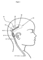
- the present invention generally provides an implantable shunt device 10 including a primary catheter 12, or trunk conduit, having a first, open end 14, and a second, connecting end 16, and at least two secondary catheters 20, or branch conduits, extending from the connecting end 16 of the primary catheter 12.
- a primary catheter 12, or trunk conduit having a first, open end 14, and a second, connecting end 16, and at least two secondary catheters 20, or branch conduits, extending from the connecting end 16 of the primary catheter 12.
- the shunt device 10 can include two or more secondary catheters 20.
- the shunt device 10 can be used for a variety of diagnostic and therapeutic procedures, including for the removal or introduction of fluid to a treatment site.
- the shunt device is used for treating hydrocephalus.
- the secondary catheters 20, and optionally at least a portion of the primary catheter 12 are implanted within one of the patient's cerebral ventricles, which contains cerebrospinal fluid (CSF).
- CSF cerebrospinal fluid
- the shunt device 10 is effective to transport fluid from the ventricle, via the secondary catheters 20 and the primary catheter 12, to another location in the body where the CSF can be absorbed into the circulatory system.
- FIG. 2A illustrates a more detailed view of the shunt device 10.
- an inner lumen 13 extends between the first and second ends 14, 16 of the primary catheter 12.
- the inner lumen 13 is in fluid communication with a fluid passageway 26a, 26b formed in each of the secondary catheters 20a, 20b, 20c.
- At least one fluid entry port 28a, 28b e.g., an inflow pore, extends through an outer wall of each of the secondary catheters 20a, 20b, 20c and into the fluid passageway 26a, 26b.
- fluid can travel through the entry ports 28a, 28b into the fluid passageway 26a, 26b of each of the secondary catheters 20a, 20b, 20c, to the inner lumen 13 of the primary catheter 12 which will direct the fluid to another site in a patient's body. Conversely, fluid can also travel in the opposite direction.
- the primary catheter 12 can have virtually any shape and size, but is preferably a substantially elongate cylindrical member having an inner lumen 13 extending therethrough.
- the open end 14 of the primary catheter 12 can be adapted for a variety of uses.
- the open end 14 of the primary catheter 12 can extend from the patient's body, can be implanted within the body, or can be mated to another medical device.
- the open end 14 is either implanted at another location within the patient's body that is adapted to receive CSF fluid from the cerebral ventricle, or is mated to a shunt valve 11 (FIG. 1) which is mated to another catheter that extends to a site in the patient's body.
- the shunt valve is effective to regulate the flow of the CSF through the system.
- the connecting end 16 of the primary catheter 12 mates to or receives the secondary catheters 20, and can have a variety of configurations.
- the connecting end 16 of the primary catheter 12 forms a seal around a distal end 22 of each of the secondary catheters 20a, 20b, 20c to retain fluid within the inner lumen 13 of the primary catheter 12.
- the connecting end 16 can include an end cap 34 having at least one bore 36 formed therein and extending into the inner lumen 13 of the primary catheter 12.
- Each bore 36a, 36b, 36c is sized to mate to or receive a distal end 22 of one of the secondary catheters 20a, 20b, 20c.
- each of the secondary catheters 20 is in fluid communication with the inner lumen 13 of the primary catheter 12.
- the end cap 34 can be formed integrally with the primary catheter 12, fixedly attached to the primary catheter 12, or it can be removably mated to the primary catheter. A variety of mating techniques can be used to connect the end cap 34 to the connecting end 16 of the primary catheter 12. By way of non-limiting example, the end cap 34 can be welded, ultrasonically bonded, adhesively attached, or mechanically mated to the primary catheter 12.
- the catheter preferably has an outer circumference C o in the range of about 2.5 mm to 3.0 mm, and more preferably about 2.7 mm.
- the inner circumference C i can also vary, but should have a size sufficient to permit fluid to flow therethrough.
- the inner circumference C i can be, for example, in the range of about 1 mm to 1.7 mm, and more preferably about 1.4 mm.
- the length of the primary tubular catheter 12 will vary depending on the intended use, but preferably the length is in the range of about 10 cm to 22 cm, and more preferably about 12 cm.
- the secondary catheters 20, which extend from the connecting end 16 of the primary catheter 12, can also have any shape and size, but are preferably elongate cylindrical members.
- the shunt device 10 can include two or more secondary catheters 20, however, for illustration purposes, the shunt device 10 is shown having three secondary catheters 20a, 20b, 20c. Referring to FIGS. 2A-2C, the secondary catheters 20a, 20b, 20c each have a proximal end 22a, 22b, 22c, a distal end 24a, 24b, 24c, and a fluid passageway 26a, 26b, 26c extending therebetween.
- the fluid passageway 26a, 26b, 26c extends through the proximal end 22a, 22b, 22c of each of the secondary catheters 20a, 20b, 20c to allow fluid to flow therethrough, and terminates at a position proximal to the distal end 24a, 24b, 24c of each of the secondary catheters 20a, 20b, 20c.
- the distal ends 24a, 24b, 24c of the secondary catheters 20a, 20b, 20c can have a variety of configurations, but are preferably rounded to facilitate insertion of the shunt device 10 into a treatment site.
- the distal ends 24a, 24b, 24c can be open or include a fluid entry port to allow fluid to flow therethrough.
- each secondary catheter 20. or a portion of each secondary catheter can have a helical shape.
- the fluid entry ports are preferably disposed on an inwardly facing surface of the helically shaped catheter.
- the secondary catheters 12a', 12b', 12c' can have a generally elongate shape, or alternatively they can have a helical shape (not shown), and can be intertwined, e.g., twisted, braided, or weaved together, to have a combined substantially cylindrical shape to facilitate insertion of the shunt device 10' into a treatment site.
- the secondary catheters can be intertwined as an alternative to using support brackets, or optionally in addition to using support brackets.
- the secondary catheters are intertwined by rotating the catheters about 360° along the central longitudinal axis L of the instrument.
- each of the secondary catheters 20a, 20b, 20c is mated to or extends into the bores 36a, 36b, 26c in the end cap 34 of the primary catheter 12.
- a proximal portion of each secondary catheter 20a, 20b, 20c extends through the bore 36a, 36b, 36c in the end cap 34 and into the inner lumen 13 of the primary catheter 12.
- the secondary catheters 20a, 20b, 20c can extend into the bores 36a, 36b, 36c in the end cap 34 and entirely through the primary catheter 12 such that the proximal ends 22a, 22b, 22c extend out the open end 14 of the primary catheter 12.
- This configuration would allow the position of the secondary catheters 20a, 20b, 20c with respect to the primary catheter 12 to be controlled.
- the proximal ends 22a, 22b, 22c could be grasped and moved in a proximal or distal direction to cause the distal ends 24a, 24b, 24c of the secondary catheters 20a, 20b, 20c to move between a position in which the secondary catheters 20a, 20b, 20c are substantially disposed within the primary member 12 and a position in which the secondary catheters 20a, 20b, 20c extend outward from the connecting end 16 of the primary catheter 12.
- the proximal ends 22a, 22b, 22c of the secondary catheters 20a, 20b, 20c are mated to the end cap 34 to form a fluid-tight seal around the bores 36 in the end cap 34.
- a variety of mating techniques can be used to connect the end cap 34 to the connecting end 16 of the primary catheter 12.
- the end cap 34 can be welded, ultrasonically bonded, adhesively attached, or mechanically mated to the primary catheter 12.
- the secondary catheters 20a, 20b, 20c each include at least one fluid entry port 28a, 28b, 28c formed therein so as to be in fluid communication with the fluid passageway 26a, 26b, 26c.
- FIG. 3 illustrates a single secondary catheter 20a having four fluid entry ports 28a.
- the size, shape, and position of the entry ports 28a can vary, but each entry port 28a should have a size and shape sufficient to allow fluid to flow therethrough and into or out of the fluid passageway 26a.
- the shape of each entry port 26a can be, for example, cylindrical, square, rectangular, etc. As shown in FIG. 3, the entry ports 28a each have a substantially cylindrical shape.
- the diameter of the entry ports 28a can also vary, but is preferably in the range of about 0.75 mm to 1.5 mm mm.
- the entry ports 28a are preferably disposed on an inwardly facing portion of each secondary catheter 20a, 20b, 20c, such that the entry ports 28a on catheter 20a face toward the entry ports 28b on catheter 20b, and the entry ports 28c (not shown) on catheter 20c. That is, the entry ports 28 should face inwardly and generally in the direction of a central longitudinal axis (L) of the shunt device. Moreover, the entry ports 28 are preferably spaced apart from each other, and are spaced apart from entry ports 28 on adjacent secondary catheters 20, as shown in FIG. 2A. A person having ordinary skill in the art will appreciate that the entry ports 28 can have virtually any size, shape, and position on the secondary catheters 20.
- each catheter preferably has an outer diameter d o in the range of about 1 mm to 1.5 mm, and an inner diameter d i , which defines the size of the fluid passageway, in the range of about 0.5 mm to 0.8 mm, as shown in FIG. 3.
- the combined nominal outer diameter d n of all of the secondary catheters 20, as shown in FIG. 2C, is preferably substantially the same as, or less than, the diameter d p of the primary catheter 12, and more preferably is in the range of about 2 mm to 3 mm.
- the shunt device 10 includes at least bracket 40, or spacing member, disposed between the secondary catheters for mating the catheters 20, and optionally for positioning the catheters at a predetermined distance apart from each other.
- the brackets 40 can have virtually any shape and size, but should be adapted to mate the secondary catheters 20 together to facilitate insertion of the shunt device 10 into a treatment site.
- the brackets 40 are particularly advantageous in that they prevent adhesion, or compression, of the secondary catheters 20a, 20b, 20c to each other during shipping, and also after the device 10 is implanted. This is particularly important since the fluid entry ports 28 are disposed on the inwardly facing portion of each secondary catheter 20.
- FIGS. 4B and 4C illustrate two embodiments of a bracket 40a, 40b for connecting, and optionally spacing apart, the secondary catheters 20.
- Bracket 40a shown in FIG. 4B, has a generally circular shape with cut-out portions 42a, 42b, 42c which are sized to receive a secondary catheter 20.
- the cut-out portions 42a, 42b, 42c are preferably spaced apart to position the secondary catheters 20a, 20b, 20c at a predetermined distance apart from each other. This allows fluid to flow in between the catheters 20a, 20b, 20c and into or out of the fluid entry ports 28a, 28b, 28c.
- the cut-out portions 42a, 42b, 42c are configured to separate the catheters 20a, 20b, 20c by a distance that is sufficient to allow fluid to flow therebetween, yet to prevent debris or tissue from entering into the space between the catheters 20a, 20b, 20c.
- the space between the secondary catheters 20a, 20b, 20c is in the range of about 0.125 mm to 0.5 mm.
- the bracket 40b shown in FIG. 4C is similar to the bracket 40a shown in FIG. 4B. However, rather than having cut-out portions 42a, 42b, 42c to receive the secondary catheters 20a, 20b, 20c, the bracket 40b has a substantially triangular shape that includes three concave portions 44a, 44b, 44c. Each secondary catheter 20a, 20b, 20c can be fixedly attached to a concave portion 44a, 44b, 44c.
- the secondary catheters 20a, 20b, 20c can be mated to the brackets 40 using a variety of techniques.
- the secondary catheters 20a, 20b, 20c can mate to the brackets 40 using an interference fit, a sliding engagement, or any other type of mating technique.
- the secondary catheters 20a, 20b, 20c can optionally be fixedly attached to the brackets 40.
- the secondary catheters 20a, 20b, 20c can be welded, ultrasonically bonded, adhesively attached, or mechanically mated to the brackets 40.
- the shunt device 10 can also be adapted to receive an endoscope or rigid stylet 60, as shown in FIG. 5.
- secondary catheter 20a is shown detached from the device 10.
- the stylet 60 can be inserted through the inner lumen 13 and the fluid passageway 26a, 26b, 26c of one of the secondary catheters 20a, 20b, 20c. More preferably, however, the stylet 60 extends within the inner lumen 13 and through a self-sealing valve 80 formed in the end cap 34 of the primary catheter 12. The stylet then passes between the secondary catheters 20a, 20b, 20c.
- the self-sealing valve 80 can have a variety of configurations such as, for example, a slit formed in the end cap 34.
- the valve 80 could also be formed from a self-sealing elastomeric membrane or septum disposed across an opening formed in the center of the end cap 34.
- a person having ordinary skill in the art will appreciate that virtually any type of self-sealing valve can be provided for allowing the stylet 60 to be inserted through the end cap 34 without allowing fluid to flow through the valve.
- the brackets 40 can also optionally include a central bore extending therethrough for slidably receive the rigid stylet 60.
- FIGS. 4B and 4C each illustrate a bracket 40a, 40b having a central bore 62a, 62b extending therethrough.
- the device 10 can include a distal cap 70 disposed around the distal ends 24a, 24b, 24c of the secondary catheters 20a, 20b, 20c.
- the distal cap 70 can have a variety of shapes and sizes, but preferably has rounded edges to prevent the device 10 from tearing or puncturing tissue while being implanted.
- the distal cap 70 is a semi-spherical object that extends entirely around the distal tips 24a, 24b, 24c of the secondary catheters 20a, 20b, 20c.
- the distal cap 70 can also be effective to prevent the rigid stylet 60 from extending beyond the distal end of the device 10 when the stylet 60 is fully inserted into the device 10.
- the distal cap 70 and brackets 40 are preferably made from a variety of biologically compatible materials. Suitable materials include, for example, titanium alloy, stainless steel, or tantalum.
- the distal cap 70 and brackets 40, 40a, 40b can optionally be formed from a bioabsorbable material, and/or a flexible, expanding material. Thus, once implanted, the end cap 70 and brackets 40 will eventually be absorbed into the body thereby allowing the secondary catheters 20a, 20b, 20c to separate.
- the primary and secondary catheters 12, 20 can also be made from a variety of biologically compatible materials. Preferably, the primary and secondary catheters 12, 20 arc made from a flexible material such as, for example, a silicone elastomer.
- stylet 60 is inserted through the primary catheter 12, the self-sealing valve 80, between the secondary catheters 20a, 20b, 20c, and through the brackets 40.
- the stylet 60 is effective to provide rigidity to the device for facilitating insertion of the device into a treatment site. Once the device 10 is implanted at the treatment site, the stylet 60 can be removed. The CSF is free to flow between the secondary catheters 20a, 20b, 20c and into the fluid entry ports 28a, 28b, 28c.
- the CSF then flows through the fluid passageway 28a, 28b, 28c, into the inner lumen 13 of the primary catheter 12, and to the open end 14 of the primary catheter where the CSF is deposited at a site in the body where it can be absorbed into the patient's circulatory system.
- an endoscope can additionally, or alternatively be used for visualizing the surgical site during implantation of the catheter.
- the endoscope can optionally provided rigidity to the catheter in place of the rigid stylet.
- the bracket 40 optionally be formed from a flexible, expanding material to allow the catheter to be used with stylets, endoscopes, or other devices having varying outer diameters.
Claims (14)
- Dispositif de shunt implantable (10) comprenant :un cathéter primaire (12) ayant une extrémité de raccordement (16), une extrémité ouverte (14) et une lumière interne (13) qui s'étend entre elles ; etune pluralité de cathéters secondaires (20) qui s'étendent de l'extrémité de raccordement (16) du cathéter primaire, chaque cathéter secondaire (20) ayant un conduit de fluide (26) formé en lui en communication fluidique avec la lumière interne (13) du cathéter primaire et au moins un orifice d'entrée de fluide (28) en communication fluidique avec le conduit de fluide (26), caractérisé en ce quel'extrémité de raccordement (16) du cathéter primaire (12) inclut une valve auto-étanchéifiante (30) adaptée pour recevoir un stylet rigide (60), la valve auto-étanchéifiante (30) étant disposée entre la lumière interne (13) du cathéter primaire et une région externe à la lumière interne du cathéter primaire.
- Dispositif de shunt implantable selon la revendication 1, dans lequel la pluralité de cathéters secondaires (20) ont un diamètre externe nominal combiné qui est sensiblement le même que ou inférieur à un diamètre externe du cathéter primaire (12).
- Dispositif de shunt implantable selon la revendication 1 ou la revendication 2, dans lequel l'extrémité de raccordement (16) du cathéter primaire (12) inclut un bouchon d'extrémité (34) ayant une pluralité d'alésages (36) s'étendant dans la lumière interne (13), chaque alésage étant adapté pour recevoir un cathéter secondaire (20).
- Dispositif de shunt implantable selon l'une quelconque des revendications 1 à 3, dans lequel la pluralité de cathéters secondaires (20) sont formés intégralement avec le cathéter primaire (12).
- Dispositif de shunt implantable selon l'une quelconque des revendications 1 à 4, dans lequel la pluralité de cathéters secondaires (20) sont entrelacés.
- Dispositif de shunt implantable selon l'une quelconque des revendications 1 à 5, comprenant, en outre, au moins une fixation de support (40) disposée entre chacun de la pluralité de cathéters secondaires (20) pour fixer les cathéters secondaires les uns aux autres.
- Dispositif de shunt implantable selon la revendication 6, dans lequel au moins une fixation de support (40) est formée à partir d'un matériau biologiquement absorbable.
- Dispositif de shunt implantable selon la revendication 6 ou la revendication 7, dans lequel la au moins une fixation de support (40) est adaptée pour positionner les cathéters secondaires (20) à une distance les uns à part des autres.
- Dispositif de shunt implantable selon l'une quelconque des revendications 6 à 8, dans lequel au moins une fixation de support (40) inclut un alésage central (62) qui s'étend à travers elle et qui est adapté pour recevoir le stylet rigide (60).
- Dispositif de shunt implantable selon l'une quelconque des revendications 6 à 9, comprenant, en outre, un stylet rigide (60) disposé de manière amovible à travers la lumière interne (13) du cathéter primaire (12), la valve auto-étanchéifiante (30) à l'extrémité de raccordement (16) du cathéter primaire, entre la pluralité de cathéters secondaires (20) et à travers la au moins une fixation de support (40).
- Dispositif de shunt implantable selon l'une quelconque des revendications 1 à 12, dans lequel chacun de la pluralité de cathéters secondaires (20) inclut une extrémité proximale (22) accouplée à l'extrémité de raccordement (16) du cathéter primaire (12) et une extrémité distale étanche (24).
- Dispositif de shunt implantable selon la revendication 11, comprenant, en outre, un bouchon distal (70) disposé autour de l'extrémité distale (24) de chacun de la pluralité de cathéters secondaires (20).
- Dispositif de shunt implantable selon l'une quelconque des revendications 1 à 12, dans lequel chacun de la pluralité de cathéters secondaires (20) inclut une paroi de cathéter avec une partie qui se tourne vers l'extérieur et une partie qui se tourne vers l'intérieur, le au moins un orifice d'entrée de fluide (28) étant disposé sur la partie qui se tourne vers l'intérieur d'au moins l'un de la pluralité de cathéters secondaires.
- Dispositif de shunt implantable selon l'une quelconque des revendications 1 à 13, dans lequel le cathéter primaire (12) et la pluralité de cathéters secondaires (20) sont formés à partir d'un matériau flexible.
Priority Applications (1)
| Application Number | Priority Date | Filing Date | Title |
|---|---|---|---|
| EP05077723A EP1712252B1 (fr) | 2002-01-14 | 2003-01-13 | Dispositif d'introduction multi-cathéter |
Applications Claiming Priority (2)
| Application Number | Priority Date | Filing Date | Title |
|---|---|---|---|
| US10/047,204 US6913589B2 (en) | 2002-01-14 | 2002-01-14 | Multi-catheter insertion device and method |
| US47204 | 2002-01-14 |
Related Child Applications (1)
| Application Number | Title | Priority Date | Filing Date |
|---|---|---|---|
| EP05077723A Division EP1712252B1 (fr) | 2002-01-14 | 2003-01-13 | Dispositif d'introduction multi-cathéter |
Publications (3)
| Publication Number | Publication Date |
|---|---|
| EP1327460A2 EP1327460A2 (fr) | 2003-07-16 |
| EP1327460A3 EP1327460A3 (fr) | 2004-01-07 |
| EP1327460B1 true EP1327460B1 (fr) | 2006-03-22 |
Family
ID=21947631
Family Applications (2)
| Application Number | Title | Priority Date | Filing Date |
|---|---|---|---|
| EP03250185A Expired - Lifetime EP1327460B1 (fr) | 2002-01-14 | 2003-01-13 | Dispositif d'introduction multi-cathéter |
| EP05077723A Expired - Lifetime EP1712252B1 (fr) | 2002-01-14 | 2003-01-13 | Dispositif d'introduction multi-cathéter |
Family Applications After (1)
| Application Number | Title | Priority Date | Filing Date |
|---|---|---|---|
| EP05077723A Expired - Lifetime EP1712252B1 (fr) | 2002-01-14 | 2003-01-13 | Dispositif d'introduction multi-cathéter |
Country Status (5)
| Country | Link |
|---|---|
| US (2) | US6913589B2 (fr) |
| EP (2) | EP1327460B1 (fr) |
| JP (1) | JP4447221B2 (fr) |
| CA (1) | CA2416333C (fr) |
| DE (2) | DE60327114D1 (fr) |
Families Citing this family (58)
| Publication number | Priority date | Publication date | Assignee | Title |
|---|---|---|---|---|
| US7700819B2 (en) | 2001-02-16 | 2010-04-20 | Kci Licensing, Inc. | Biocompatible wound dressing |
| US7763769B2 (en) | 2001-02-16 | 2010-07-27 | Kci Licensing, Inc. | Biocompatible wound dressing |
| WO2003015710A2 (fr) * | 2001-08-21 | 2003-02-27 | Eunoe, Inc. | Therapies et systemes combinant l'administration de medicament et l'extraction de liquide cephalorachidien |
| US6913589B2 (en) * | 2002-01-14 | 2005-07-05 | Codman & Shurtleff, Inc. | Multi-catheter insertion device and method |
| US9694166B2 (en) | 2002-03-26 | 2017-07-04 | Medtronics Ps Medical, Inc. | Method of draining cerebrospinal fluid |
| US9345456B2 (en) * | 2004-03-24 | 2016-05-24 | Devicor Medical Products, Inc. | Biopsy device |
| US7464862B2 (en) * | 2004-06-15 | 2008-12-16 | Quickvault, Inc. | Apparatus & method for POS processing |
| JP4370230B2 (ja) * | 2004-09-08 | 2009-11-25 | 株式会社カネカメディックス | 医療用チューブおよびシャントシステム |
| US7678101B2 (en) | 2005-05-20 | 2010-03-16 | Medtronic, Inc. | Locking catheter connector and connection system |
| US20070078398A1 (en) * | 2005-08-27 | 2007-04-05 | Dextradeur Alan J | Multi-branched anti-reflux valve |
| US8206334B2 (en) * | 2006-01-31 | 2012-06-26 | Kralick Francis A | Implantable micro-system for treatment of hydrocephalus |
| CA2641034C (fr) * | 2006-01-31 | 2013-04-09 | Francis A. Kralick | Micro-systeme implantable pour le traitement de l'hydrocephalie |
| US8652090B2 (en) * | 2006-05-18 | 2014-02-18 | Cannuflow, Inc. | Anti-extravasation surgical portal plug |
| US8551075B2 (en) | 2006-06-02 | 2013-10-08 | Kci Medical Resources | Assemblies, systems, and methods for vacuum assisted internal drainage during wound healing |
| US8715267B2 (en) | 2006-06-02 | 2014-05-06 | Kci Medical Resources | Assemblies, systems, and methods for vacuum assisted internal drainage during wound healing |
| WO2007143179A2 (fr) | 2006-06-02 | 2007-12-13 | Bengtson Bradley P | Assemblages, systèmes et méthodes pour aspiration assistée de drainage interne pendant la cicatrisation d'une plaie |
| US20080283048A1 (en) * | 2007-05-16 | 2008-11-20 | Johan Petersen | Two-stage reduction of aerosol droplet size |
| US8460229B2 (en) | 2007-08-17 | 2013-06-11 | The Invention Science Fund I, Llc | Systems, devices, and methods including catheters having components that are actively controllable between transmissive and reflective states |
| US8734718B2 (en) | 2007-08-17 | 2014-05-27 | The Invention Science Fund I, Llc | Systems, devices, and methods including catheters having an actively controllable therapeutic agent delivery component |
| US8366652B2 (en) * | 2007-08-17 | 2013-02-05 | The Invention Science Fund I, Llc | Systems, devices, and methods including infection-fighting and monitoring shunts |
| US8706211B2 (en) | 2007-08-17 | 2014-04-22 | The Invention Science Fund I, Llc | Systems, devices, and methods including catheters having self-cleaning surfaces |
| US8162924B2 (en) | 2007-08-17 | 2012-04-24 | The Invention Science Fund I, Llc | System, devices, and methods including actively-controllable superoxide water generating systems |
| US8647292B2 (en) | 2007-08-17 | 2014-02-11 | The Invention Science Fund I, Llc | Systems, devices, and methods including catheters having components that are actively controllable between two or more wettability states |
| US20090048648A1 (en) * | 2007-08-17 | 2009-02-19 | Searete Llc, A Limited Liability Corporation Of The State Of Delaware | Self-sterilizing device |
| US8702640B2 (en) | 2007-08-17 | 2014-04-22 | The Invention Science Fund I, Llc | System, devices, and methods including catheters configured to monitor and inhibit biofilm formation |
| US8114346B2 (en) * | 2007-08-17 | 2012-02-14 | The Invention Science Fund I, Llc | Event-triggered ultraviolet light sterilization of surfaces |
| US8753304B2 (en) | 2007-08-17 | 2014-06-17 | The Invention Science Fund I, Llc | Systems, devices, and methods including catheters having acoustically actuatable waveguide components for delivering a sterilizing stimulus to a region proximate a surface of the catheter |
| US8029740B2 (en) * | 2008-07-11 | 2011-10-04 | The Invention Science Fund I, Llc | Event-triggered self-sterilization of article surfaces |
| US20110190778A1 (en) * | 2008-07-28 | 2011-08-04 | Paul Arpasi | Multiple Port Introducer for Thrombolysis |
| JP5329154B2 (ja) * | 2008-08-28 | 2013-10-30 | 日本コヴィディエン株式会社 | 医療用チューブセット |
| US8585627B2 (en) | 2008-12-04 | 2013-11-19 | The Invention Science Fund I, Llc | Systems, devices, and methods including catheters configured to monitor biofilm formation having biofilm spectral information configured as a data structure |
| US20110295090A1 (en) | 2008-12-04 | 2011-12-01 | Searete Llc, A Limited Liability Corporation Of The State Of Delaware | Systems, devices, and methods including implantable devices with anti-microbial properties |
| EP2384168B1 (fr) | 2008-12-04 | 2014-10-08 | Searete LLC | Implants de distribution d'excitation stérilisants à commande active |
| US9233237B2 (en) * | 2010-08-26 | 2016-01-12 | New York University | Apparatus and method for periodic fluid-delivery/fluid-removal cycles in the cranial subarachnoid space to treat cerebral cortical disorders |
| US20120078159A1 (en) * | 2010-09-29 | 2012-03-29 | Codman & Shurtleff, Inc | Multi-lumen ventricular drainage catheter |
| US8728011B2 (en) | 2011-07-22 | 2014-05-20 | Michael D. Khoury | Multi wire sheath |
| US9101678B2 (en) | 2011-11-03 | 2015-08-11 | Elwha Llc | Heat-sanitization of surfaces |
| US9901707B2 (en) * | 2012-05-23 | 2018-02-27 | Integra Lifesciences Switzerland Sàrl | Catheter curvature braces and methods of using same |
| US9381330B2 (en) * | 2012-06-14 | 2016-07-05 | Michel Carrier | Drain catheter |
| JP5966709B2 (ja) * | 2012-07-17 | 2016-08-10 | ニプロ株式会社 | トロッカーカテーテル、これに用いられる外套カテーテル、及び内針 |
| EP3466457B1 (fr) * | 2012-12-06 | 2023-03-08 | IC Surgical, Inc. | Système de drainage de plaie adaptable |
| EP2948209B1 (fr) * | 2013-01-22 | 2018-11-21 | Anuncia, Inc. | Dispositif rinçage d'un système de dérivation |
| WO2014145858A2 (fr) | 2013-03-15 | 2014-09-18 | Bitol Designs, Llc | Cathéter résistant à une occlusion et procédé d'utilisation |
| EP3131617B1 (fr) | 2014-04-18 | 2019-12-11 | Anuncia, Inc. | Systèmes de dérivation d'un fluide |
| EP3302677A4 (fr) * | 2015-06-01 | 2019-02-20 | University of Massachusetts | Ensembles cathéter |
| US11511035B2 (en) * | 2016-07-28 | 2022-11-29 | Cerebral Therapeutics, Inc. | Implantable intraventricular sampling and infusion access device |
| CN114712674A (zh) | 2016-10-13 | 2022-07-08 | 安嫩西亚医疗公司 | 分流冲洗器和相关方法 |
| US10518069B2 (en) * | 2016-10-28 | 2019-12-31 | Integra LifeSciences Switzerland Sarl | Implantable valve assembly with extended lifespan |
| US10737076B2 (en) * | 2016-12-21 | 2020-08-11 | Integra LifeSciences Switzerland Sárl | Self-offsetting implantable catheter system |
| CN107361801A (zh) * | 2017-05-16 | 2017-11-21 | 李茂雷 | 神经内镜通道 |
| US10500331B2 (en) | 2017-08-18 | 2019-12-10 | Ayman H. Al-Jazaeri | Drainage catheter with retractable internal drains |
| WO2019240885A2 (fr) * | 2018-04-26 | 2019-12-19 | Augusta University Research Institute, Inc. | Procédé d'élimination de fluide à partir du corps et dispositif associé |
| CN113164557A (zh) | 2018-07-23 | 2021-07-23 | 因柯利尔疗法公司 | 治疗神经性病症的方法 |
| JP2022510573A (ja) | 2018-07-23 | 2022-01-27 | エンクリアー セラピーズ, インク. | 神経障害の治療方法 |
| CN114007665A (zh) | 2019-04-11 | 2022-02-01 | 因柯利尔疗法公司 | 改善脑脊液的方法及其装置和系统 |
| JP7395843B2 (ja) | 2019-05-10 | 2023-12-12 | ニプロ株式会社 | ドレーンカテーテル |
| US10765847B1 (en) | 2019-12-10 | 2020-09-08 | Ayman H. Al-Jazaeri | Single lumen drainage catheter with extendable and retractable drains |
| US11690739B1 (en) | 2020-08-25 | 2023-07-04 | Francis A. Kralick | Implantable device for treatment of hydrocephalus |
Family Cites Families (35)
| Publication number | Priority date | Publication date | Assignee | Title |
|---|---|---|---|---|
| US3144868A (en) * | 1960-10-21 | 1964-08-18 | Mario E Jascalevich | Drainage and feeding cannulae |
| US3867937A (en) * | 1972-12-07 | 1975-02-25 | Boris Schwartz | Flexible protective sheath for catheter |
| US3867945A (en) * | 1973-05-14 | 1975-02-25 | Wendell M Long | Catheter stylets |
| US4072153A (en) * | 1976-03-03 | 1978-02-07 | Swartz William H | Post hysterectomy fluid drainage tube |
| JPS5345083A (en) * | 1976-10-05 | 1978-04-22 | Tokyo Ika Shika Daigakuchiyou | Silicon double tract for discharging fluid |
| US4215695A (en) * | 1978-02-22 | 1980-08-05 | Medical Devices, Inc. | Fluid draining system |
| US4406656A (en) * | 1981-06-01 | 1983-09-27 | Brack Gillium Hattler | Venous catheter having collapsible multi-lumens |
| US4432853A (en) * | 1981-06-10 | 1984-02-21 | The United States Of America As Represented By The Administrator Of The National Aeronautics And Space Administration | Method of making an ion beam sputter-etched ventricular catheter for hydrocephalus shunt |
| US4377169A (en) * | 1981-06-10 | 1983-03-22 | Banks Bruce A | Ion beam sputter-etched ventricular catheter for hydrocephalus shunt |
| US4578057A (en) * | 1984-08-31 | 1986-03-25 | Cordis Corporation | Ventricular right angle connector and system |
| DE3445560C1 (de) * | 1984-12-14 | 1986-04-30 | pfm Plastik für die Medizin GmbH, 5000 Köln | Katheter |
| US4655745A (en) * | 1985-07-29 | 1987-04-07 | Corbett Joseph E | Ventricular catheter |
| US4950232A (en) * | 1987-08-11 | 1990-08-21 | Surelab Superior Research Laboratories | Cerebrospinal fluid shunt system |
| US4784638A (en) * | 1987-09-17 | 1988-11-15 | Neurodynamics, Inc. | Angled hole ventricular catheter and method of making same |
| EP0382753A4 (en) | 1987-09-17 | 1991-01-30 | Neurodynamics, Inc. | Angled hole ventricular catheter |
| US4767400A (en) * | 1987-10-27 | 1988-08-30 | Cordis Corporation | Porous ventricular catheter |
| US4925452A (en) * | 1988-03-08 | 1990-05-15 | Uresil Corporation | Multiple conduit drainage device |
| US4950224A (en) * | 1988-08-05 | 1990-08-21 | Healthdyne, Inc. | Apparatus and method for in vivo plasma separation |
| DE69007465T2 (de) | 1989-10-11 | 1994-10-20 | Baxter Int | Integrierter intrakranialer druckmonitor und drainagekatheter. |
| US5098411A (en) * | 1991-06-10 | 1992-03-24 | Pudenz-Schulte Medical Research Corporation | Closed end hollow stylet assembly |
| US5405316A (en) * | 1993-11-17 | 1995-04-11 | Magram; Gary | Cerebrospinal fluid shunt |
| US5531673A (en) * | 1995-05-26 | 1996-07-02 | Helenowski; Tomasz K. | Ventricular catheter |
| US5913852A (en) * | 1995-07-21 | 1999-06-22 | Nemours Foundation | Drain cannula |
| AU717069B2 (en) | 1996-09-18 | 2000-03-16 | Sinu Shunt A/S | Device for the treatment of hydrocephalus |
| JP3413335B2 (ja) | 1996-12-25 | 2003-06-03 | 株式会社ナムコ | ゲームシステム |
| FR2761891B1 (fr) * | 1997-04-14 | 1999-09-24 | Synthelabo | Drain chirurgical souple pourvu d'une pluralite de conduits individuels |
| US6030358A (en) * | 1997-08-08 | 2000-02-29 | Odland; Rick Matthew | Microcatheter and method for site specific therapy |
| US5897528A (en) * | 1998-04-30 | 1999-04-27 | Medtronic, Inc. | Filtered intracerebroventricular or intraspinal access port with direct cerebrospinal fluid access |
| US6013051A (en) * | 1998-10-22 | 2000-01-11 | Medtronic, Inc. | Filtered access port with filter bypass for accessing body fluid samples |
| US6254610B1 (en) * | 1999-05-24 | 2001-07-03 | Impulse Dynamics N.V. | Device and method for dragging and positioning a member within a duct in a body |
| US6193691B1 (en) | 1999-03-30 | 2001-02-27 | Depuy Orthopaedics, Inc. | Catheter system |
| US6616652B1 (en) * | 2000-02-15 | 2003-09-09 | Microsolutions, Inc. | Osmotic pump delivery system with pre-hydrated membrane(s) and/or primable catheter |
| US6814718B2 (en) * | 2001-01-09 | 2004-11-09 | Rex Medical, L.P | Dialysis catheter |
| US6913589B2 (en) * | 2002-01-14 | 2005-07-05 | Codman & Shurtleff, Inc. | Multi-catheter insertion device and method |
| US7037288B2 (en) * | 2002-01-14 | 2006-05-02 | Codman & Shurtleff, Inc. | Anti-block catheter |
-
2002
- 2002-01-14 US US10/047,204 patent/US6913589B2/en not_active Expired - Lifetime
-
2003
- 2003-01-10 JP JP2003004944A patent/JP4447221B2/ja not_active Expired - Fee Related
- 2003-01-13 EP EP03250185A patent/EP1327460B1/fr not_active Expired - Lifetime
- 2003-01-13 DE DE60327114T patent/DE60327114D1/de not_active Expired - Lifetime
- 2003-01-13 DE DE60304112T patent/DE60304112T2/de not_active Expired - Lifetime
- 2003-01-13 EP EP05077723A patent/EP1712252B1/fr not_active Expired - Lifetime
- 2003-01-14 CA CA2416333A patent/CA2416333C/fr not_active Expired - Lifetime
-
2005
- 2005-03-16 US US11/081,577 patent/US7699800B2/en not_active Expired - Lifetime
Also Published As
| Publication number | Publication date |
|---|---|
| EP1712252A1 (fr) | 2006-10-18 |
| US20030135148A1 (en) | 2003-07-17 |
| DE60304112T2 (de) | 2007-03-29 |
| US7699800B2 (en) | 2010-04-20 |
| EP1712252B1 (fr) | 2009-04-08 |
| US20050159697A1 (en) | 2005-07-21 |
| US6913589B2 (en) | 2005-07-05 |
| DE60327114D1 (de) | 2009-05-20 |
| JP2003235987A (ja) | 2003-08-26 |
| EP1327460A2 (fr) | 2003-07-16 |
| DE60304112D1 (de) | 2006-05-11 |
| CA2416333C (fr) | 2011-05-24 |
| EP1327460A3 (fr) | 2004-01-07 |
| CA2416333A1 (fr) | 2003-07-14 |
| JP4447221B2 (ja) | 2010-04-07 |
Similar Documents
| Publication | Publication Date | Title |
|---|---|---|
| EP1327460B1 (fr) | Dispositif d'introduction multi-cathéter | |
| EP1327459B1 (fr) | Catheter antiadhérent | |
| AU2016204328B2 (en) | Multi-lumen ventricular drainage catheter | |
| US7226441B2 (en) | Catheter with block-overriding system | |
| RU2193901C2 (ru) | Катетер, в частности для перитонеального диализа | |
| EP0637971B1 (fr) | Derivation du liquide cephalo-rachidien permettant un controle invasif minimal | |
| JP4309649B2 (ja) | 脳脊髄液シャント装置および水頭症治療方法 | |
| US5098411A (en) | Closed end hollow stylet assembly | |
| WO2003089031A1 (fr) | Catheter spinal sous-arachnoidien destine au transport d'un liquide cephalo-rachidien | |
| JP4417013B2 (ja) | 閉塞防止カテーテル | |
| US7094214B2 (en) | System and method for clearing an implanted catheter that is connected to a shunt | |
| EP2666506B1 (fr) | Entretoises de courbure de cathéter | |
| US10737076B2 (en) | Self-offsetting implantable catheter system |
Legal Events
| Date | Code | Title | Description |
|---|---|---|---|
| PUAI | Public reference made under article 153(3) epc to a published international application that has entered the european phase |
Free format text: ORIGINAL CODE: 0009012 |
|
| AK | Designated contracting states |
Designated state(s): AT BE BG CH CY CZ DE DK EE ES FI FR GB GR HU IE IT LI LU MC NL PT SE SI SK TR |
|
| AX | Request for extension of the european patent |
Extension state: AL LT LV MK RO |
|
| PUAL | Search report despatched |
Free format text: ORIGINAL CODE: 0009013 |
|
| AK | Designated contracting states |
Kind code of ref document: A3 Designated state(s): AT BE BG CH CY CZ DE DK EE ES FI FR GB GR HU IE IT LI LU MC NL PT SE SI SK TR |
|
| AX | Request for extension of the european patent |
Extension state: AL LT LV MK RO |
|
| 17P | Request for examination filed |
Effective date: 20040621 |
|
| 17Q | First examination report despatched |
Effective date: 20040729 |
|
| AKX | Designation fees paid |
Designated state(s): DE FR GB IT |
|
| GRAP | Despatch of communication of intention to grant a patent |
Free format text: ORIGINAL CODE: EPIDOSNIGR1 |
|
| RTI1 | Title (correction) |
Free format text: MULTI-CATHETER INSERTION DEVICE |
|
| GRAS | Grant fee paid |
Free format text: ORIGINAL CODE: EPIDOSNIGR3 |
|
| GRAA | (expected) grant |
Free format text: ORIGINAL CODE: 0009210 |
|
| AK | Designated contracting states |
Kind code of ref document: B1 Designated state(s): DE FR GB IT |
|
| PG25 | Lapsed in a contracting state [announced via postgrant information from national office to epo] |
Ref country code: IT Free format text: LAPSE BECAUSE OF FAILURE TO SUBMIT A TRANSLATION OF THE DESCRIPTION OR TO PAY THE FEE WITHIN THE PRESCRIBED TIME-LIMIT;WARNING: LAPSES OF ITALIAN PATENTS WITH EFFECTIVE DATE BEFORE 2007 MAY HAVE OCCURRED AT ANY TIME BEFORE 2007. THE CORRECT EFFECTIVE DATE MAY BE DIFFERENT FROM THE ONE RECORDED. Effective date: 20060322 |
|
| REG | Reference to a national code |
Ref country code: GB Ref legal event code: FG4D |
|
| REF | Corresponds to: |
Ref document number: 60304112 Country of ref document: DE Date of ref document: 20060511 Kind code of ref document: P |
|
| ET | Fr: translation filed | ||
| PLBE | No opposition filed within time limit |
Free format text: ORIGINAL CODE: 0009261 |
|
| STAA | Information on the status of an ep patent application or granted ep patent |
Free format text: STATUS: NO OPPOSITION FILED WITHIN TIME LIMIT |
|
| 26N | No opposition filed |
Effective date: 20061227 |
|
| REG | Reference to a national code |
Ref country code: FR Ref legal event code: PLFP Year of fee payment: 14 |
|
| REG | Reference to a national code |
Ref country code: FR Ref legal event code: PLFP Year of fee payment: 15 |
|
| REG | Reference to a national code |
Ref country code: FR Ref legal event code: PLFP Year of fee payment: 16 |
|
| REG | Reference to a national code |
Ref country code: GB Ref legal event code: 732E Free format text: REGISTERED BETWEEN 20180712 AND 20180718 |
|
| REG | Reference to a national code |
Ref country code: GB Ref legal event code: 732E Free format text: REGISTERED BETWEEN 20180719 AND 20180725 |
|
| REG | Reference to a national code |
Ref country code: DE Ref legal event code: R082 Ref document number: 60304112 Country of ref document: DE Representative=s name: MUELLER-BORE & PARTNER PATENTANWAELTE PARTG MB, DE Ref country code: DE Ref legal event code: R081 Ref document number: 60304112 Country of ref document: DE Owner name: INTEGRA LIFESCIENCES SWITZERLAND SARL, CH Free format text: FORMER OWNER: CODMAN & SHURTLEFF, INC., RAYNHAM, MASS., US |
|
| PGFP | Annual fee paid to national office [announced via postgrant information from national office to epo] |
Ref country code: GB Payment date: 20211125 Year of fee payment: 20 Ref country code: FR Payment date: 20211125 Year of fee payment: 20 |
|
| PGFP | Annual fee paid to national office [announced via postgrant information from national office to epo] |
Ref country code: DE Payment date: 20211116 Year of fee payment: 20 |
|
| PGFP | Annual fee paid to national office [announced via postgrant information from national office to epo] |
Ref country code: IT Payment date: 20211213 Year of fee payment: 20 |
|
| REG | Reference to a national code |
Ref country code: DE Ref legal event code: R071 Ref document number: 60304112 Country of ref document: DE |
|
| REG | Reference to a national code |
Ref country code: GB Ref legal event code: PE20 Expiry date: 20230112 |
|
| PG25 | Lapsed in a contracting state [announced via postgrant information from national office to epo] |
Ref country code: GB Free format text: LAPSE BECAUSE OF EXPIRATION OF PROTECTION Effective date: 20230112 |