EP1326249A2 - Behälter für ein elekronisches Gerät - Google Patents
Behälter für ein elekronisches Gerät Download PDFInfo
- Publication number
- EP1326249A2 EP1326249A2 EP03250004A EP03250004A EP1326249A2 EP 1326249 A2 EP1326249 A2 EP 1326249A2 EP 03250004 A EP03250004 A EP 03250004A EP 03250004 A EP03250004 A EP 03250004A EP 1326249 A2 EP1326249 A2 EP 1326249A2
- Authority
- EP
- European Patent Office
- Prior art keywords
- holder
- holder according
- heat
- electrical
- heat conducting
- Prior art date
- Legal status (The legal status is an assumption and is not a legal conclusion. Google has not performed a legal analysis and makes no representation as to the accuracy of the status listed.)
- Withdrawn
Links
Images





Classifications
-
- G—PHYSICS
- G11—INFORMATION STORAGE
- G11B—INFORMATION STORAGE BASED ON RELATIVE MOVEMENT BETWEEN RECORD CARRIER AND TRANSDUCER
- G11B33/00—Constructional parts, details or accessories not provided for in the other groups of this subclass
- G11B33/14—Reducing influence of physical parameters, e.g. temperature change, moisture, dust
Definitions
- the present invention relates to a holder or cradle for location in or with a housing or frame of electrical apparatus, and particularly but not exclusively to a mounting cradle for a hard disk drive for location in electrical apparatus.
- the above described method is sufficient to reduce heat from components located a small pre-determined distance from a surface of the apparatus housing, if the pre-determined distance becomes larger, the method described in EP1107657 can become impractical.
- the heat dissipation means in EP1107657 may not be sufficient or practical for maintaining the temperature in the locality of the component within the required working temperature range.
- a hard disk drive of a set top box or broadcast data receiver is required to be located a spaced distance from the surface of the housing of the receiver to reduce the noise generated therefrom. This is achieved by using a cradle in which to mount the hard disk drive.
- the heat dissipation method of providing a raised platform in the apparatus housing is likely to be insufficient to dissipate heat from the cradle.
- a holder for location with a housing or frame of electrical apparatus, said holder having one or more heat producing electrical components mounted thereon, characterised in that the holder includes at least one heat conducting member protruding from a surface thereof for directly or indirectly contacting said electrical component or components, said at least one heat conducting member conducting heat away from said electrical component(s) and said holder when said electrical apparatus is in use.
- heat transfer material is provided between said at least one heat conducting member and said electrical component or components.
- the at least one heat conducting member and the heat transfer material conducts heat away from the electrical components and the holder when the electrical apparatus is in use.
- the heat conducting members are integrally formed with the holder.
- the heat conducting members and holder are integrally formed by die casting from aluminium.
- one or more of the heat conducting members can be attached to the holder if required.
- the members can also be detachably attached to allow movement of the members to locations on the cradle where most heat dissipation is required.
- the holder has location means for locating the same at a required location in, on, with or relative to the housing or frame of the electrical apparatus.
- the location means includes one or more mounting pillars which maintain the main body of the holder in spaced relationship from the housing of the electrical apparatus.
- the one or more mounting pillars typically extend downwardly from the base of the holder and locate on the base of the electrical apparatus.
- Location ports in the form of apertures or recesses can be provided on the base of the apparatus to allow engagement of said pillars therein.
- one or more supporting arm members are provided for supporting the holder at a required position in said electrical apparatus.
- the supporting arms can be provided between the holder and the side walls, base, or top of the housing or frame of the electrical apparatus, or can be connected to some other component within the electrical apparatus.
- one or more supporting foot members are provided on the location means.
- the supporting foot members protrude from a surface of the location means to contact a surface of the electrical apparatus or further electrical component within the apparatus.
- the holder is a hard disk drive mounting cradle for location in the housing of an electrical device, such as a set top box or broadcast data receiver.
- a plurality of heat conducting members are provided at a number of spaced locations on the holder.
- the heat conducting members are in the form of finger like protrusions, thereby providing a large surface area from which heat can be dissipated.
- the position of the members correspond to the position of Integrated Circuit (IC) boards or other electronic components located thereon, such as a motor for use with a hard disk drive or for use with the electrical apparatus.
- IC Integrated Circuit
- the heat conducting members protrude outwardly from one or more surfaces of the holder.
- the holder is mounted via the mounting pillars on the base of the electrical apparatus such that a pre-determined space exists between the base of the holder body and the base of the apparatus.
- the holder can be mounted so as to form a pre-determined space between one or more further surfaces of the holder and one or more surfaces of the apparatus.
- the heat conducting members protrude downwardly from the base of the holder body into said pre-determined space and/or upwardly to make contact directly or indirectly with the ICs of the hard disk drive or other electrical component(s).
- the holder is provided with securing means for securing the hard disk drive or other electrical component to the holder when the electrical apparatus is constructed.
- the securing means can include any or any combination of nuts and bolts, clips, screws, adhesive, welding and/or the like.
- the heat transfer material includes one or more gel pads.
- a hard disk drive mounting cradle for location with a housing or frame of electrical apparatus, said mounting cradle for supporting a hard disk drive within the electrical apparatus and said hard disk drive containing one or more heat producing electrical components mounted therein, characterised in that said mounting cradle includes at least one heat conducting member protruding from a surface thereof for directly or indirectly contacting the heat producing electrical component or components, said at least one heat conducting member conducting heat away from said electrical component(s) and said mounting cradle.
- electrical apparatus having a holder located therein, said holder having one or more heat producing electrical components mounted thereon, characterised in that the holder includes at least one heat conducting member protruding from a surface thereof for directly or indirectly contacting said electrical component or components, said at least one heat conducting member conducting heat away from said electrical component(s) and said holder when said electrical apparatus is in use.
- An advantage of the present invention is that the heat sinks provided by the heat conducting members of the holder rapidly conduct heat away from the hard disk drive and its electrical components in addition to any further heatsink(s) provided in the housing of the electrical apparatus.
- the heat conducting members can protrude in opposite directions from the holder to maximise the conductance of heat from the electrical components.
- the heat sinks maintain the hard disk drive at an acceptable working temperature, thereby removing or minimising the requirement for a cooling fan or other heat dissipation means to be provided in the housing of the electrical apparatus.
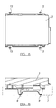
- a cradle 2 for the mounting of a hard disk drive 3 therein.
- the cradle and hard disk drive 3 are located in a housing or frame of a broadcast data receiver (BDR) when in use, as shown in figures 4-6.
- BDR broadcast data receiver
- the BDR receives digital data from a broadcaster at a remote location and decodes and processes said data to provide audio, video and/or auxiliary data for viewing on a television display screen connected to the BDR or forming a part thereof and/or for listening via speakers.
- the cradle 2 is provided with three mounting pillars 4, 6, 8 for positioning the cradle at a pre-determined position in the BDR, and typically for mounting the cradle body 10 and thus the hard disk drive 3 in a spaced relationship from the base of the BDR housing.
- the base of the BDR housing typically has location recesses or apertures 9 in which the mounting pillars can locate, as indicated in part by dotted line 7 in figure 6.
- the cradle 2 is further provided with securing means in the form of hard disk drive mounting apertures 12 for the location of securing screws 13 for fixing the disk drive 3 to the cradle 2 in use.
- the mounting apertures 12 are defined in upwardly protruding arms 15, which act as a frame to provide further support for the hard disk drive.
- Heatsinks 14, 16 and 18 are provided in the cradle to conduct heat away from the disk drive.
- the heatsinks are located at pre-determined positions corresponding to the position of electrical components (not shown) in or on the hard disk drive 3.
- Heat transfer gel pads 20, 22 and 24 are located between heatsinks 14, 16 and 18 respectively and the electrical components of the hard disk drive or hard disk drive housing.
- the heatsinks comprise a number of finger-like members 25 which protrude upwardly from the upper base surface 26 of the cradle body 10 and downwardly below the lower base surface 28 of body 10. This maximises the heat transfer from the components of the hard disk drive and into other areas of the BDR.
- the finger like members are spaced a pre-determined distance apart from each other which is sufficient to allow heat dissipation.
- the mounting pillars 4, 6, 8 also act as heat conducting members to conduct heat from the cradle to the housing of the BDR.
- the heatsinks 14, 16 and 18 are integrally formed with the cradle by die casting, typically from a lightweight material such as aluminium. Apertures 30 are provided in the cradle to reduce the amount of material required to mount the disk drive in the BDR.
- the heat transfer material can be formed as an integral part of the heat conducting members.
- the longitudinal dimensions of the heat conducting members are typically substantially larger than the cross-sectional dimensions, thereby providing a larger surface area for heat conductance.
- the cradle 2 also integrates the mechanical compliance/damping required to reduce the effects that the torque generated by the hard disk drive voice coil has on the registration of the read/record head.
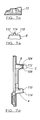
- FIGS. 7a-7i there is illustrated a cradle 102 according to a further embodiment of the present invention.
- the same reference numerals are used in these figures to identify the same components of the cradle as in figures 1-6.
- the mounting pillars 4, 6, 8 have a channel 104 therethrough with an opening 106 on the top surface 26 of the cradle and an opening 108 on the underside surface 28 of the cradle.
- the provision of channel 104 through the mounting pillars reduces the amount of material required to form the same and provides a larger surface area for heat dissipation.
- a protruding foot member 112 is provided at end 110 of each mounting pillar to allow improved location of the pillars in corresponding recesses in the housing of the BDR.
- a rubber cap 114 can be provided on the foot member to prevent slipping of the holder relative to the housing and to reduce vibration and/or noise.
- Heatsinks 14, 16, 18 are provided in different locations on the cradle 102 compared to the cradle 2 due to different arrangements of electrical components requiring heat dissipation therefrom.
- An additional heat sink 116 is also provided in cradle 102.
- the finger like protrusions 25 are typically in the form of sheet like plates located a pre-determined spaced distance apart from each other.
- Mounting apertures 12 are defined in arms 118 protruding from the main body 10 of cradle 102 for securing a hard disk drive or other electrical component thereto. Arms 118 are substantially planar with upper surface 26 of cradle 102.
- Apertures 30 are also provided on cradle 102 but are provided in greater number and different positions than the apertures provided in cradle 2.
- the apertures are typically located according to where minimum support is required for the one or more electrical components mounted on the cradle.
- the holder of the present invention can be used in any number of different electrical devices for mounting components or units in the housing or frame of the device, in addition to any additional heatsinks or heat conducting means provided in the housing of the device.
- the number and size of the heatsinks can be varied according to the number and size of the components with which the heatsinks directly or indirectly contact.
Landscapes
- Cooling Or The Like Of Electrical Apparatus (AREA)
Applications Claiming Priority (2)
| Application Number | Priority Date | Filing Date | Title |
|---|---|---|---|
| GB0200138A GB0200138D0 (en) | 2002-01-04 | 2002-01-04 | A holder for electrical apparatus |
| GB0200138 | 2002-01-04 |
Publications (2)
| Publication Number | Publication Date |
|---|---|
| EP1326249A2 true EP1326249A2 (de) | 2003-07-09 |
| EP1326249A3 EP1326249A3 (de) | 2003-07-30 |
Family
ID=9928623
Family Applications (1)
| Application Number | Title | Priority Date | Filing Date |
|---|---|---|---|
| EP03250004A Withdrawn EP1326249A3 (de) | 2002-01-04 | 2003-01-02 | Behälter für ein elekronisches Gerät |
Country Status (2)
| Country | Link |
|---|---|
| EP (1) | EP1326249A3 (de) |
| GB (1) | GB0200138D0 (de) |
Cited By (1)
| Publication number | Priority date | Publication date | Assignee | Title |
|---|---|---|---|---|
| EP1610600A2 (de) | 2004-06-15 | 2005-12-28 | Pace Micro Technology PLC | Verbesserungen eines elektronischen Gerätes |
Family Cites Families (5)
| Publication number | Priority date | Publication date | Assignee | Title |
|---|---|---|---|---|
| US5598320A (en) * | 1995-03-06 | 1997-01-28 | Ast Research, Inc. | Rotable and slideble heat pipe apparatus for reducing heat build up in electronic devices |
| US6320723B1 (en) * | 1999-06-24 | 2001-11-20 | Seagate Technology Llc | Protective cover for a disc drive printed circuit board wherein the cover and a circuit board component are thermally connected |
| GB9928862D0 (en) * | 1999-12-08 | 2000-02-02 | Pace Micro Tech Plc | Means for dissipating heat to electrical apparatus |
| US6239972B1 (en) * | 1999-12-13 | 2001-05-29 | Honeywell International Inc. | Integrated convection and conduction heat sink for multiple mounting positions |
| GB2358521A (en) * | 2000-01-24 | 2001-07-25 | Chen Yang Shiau | Heat sink structure adapted for use in a computer housing |
-
2002
- 2002-01-04 GB GB0200138A patent/GB0200138D0/en not_active Ceased
-
2003
- 2003-01-02 EP EP03250004A patent/EP1326249A3/de not_active Withdrawn
Cited By (2)
| Publication number | Priority date | Publication date | Assignee | Title |
|---|---|---|---|---|
| EP1610600A2 (de) | 2004-06-15 | 2005-12-28 | Pace Micro Technology PLC | Verbesserungen eines elektronischen Gerätes |
| EP1610600A3 (de) * | 2004-06-15 | 2009-04-22 | Pace Plc | Verbesserungen eines elektronischen Gerätes |
Also Published As
| Publication number | Publication date |
|---|---|
| EP1326249A3 (de) | 2003-07-30 |
| GB0200138D0 (en) | 2002-02-20 |
Similar Documents
| Publication | Publication Date | Title |
|---|---|---|
| US7755902B2 (en) | Heat dissipation device for computer add-on cards | |
| US5390078A (en) | Apparatus for using an active circuit board as a heat sink | |
| US20050030719A1 (en) | Heat dissipating device for dissipating heat generated by an electronic component inside a housing | |
| US8081458B2 (en) | Heat dissipation apparatus for electronic device | |
| US8322404B2 (en) | Heat dissipation device for at least two electronic devices with two sets of fins | |
| JP4799296B2 (ja) | 電子機器 | |
| US7537049B2 (en) | Heat dissipation apparatus | |
| JP3722616B2 (ja) | 情報端末機器 | |
| US7203065B1 (en) | Heatsink assembly | |
| US6958909B2 (en) | Electronic apparatus | |
| JP2010287796A (ja) | 電子機器 | |
| US6417563B1 (en) | Spring frame for protecting packaged electronic devices | |
| US7414839B2 (en) | Heat dissipation device having a fan holder for attachment of a fan | |
| EP1326249A2 (de) | Behälter für ein elekronisches Gerät | |
| US20050270741A1 (en) | Large-area planar heat dissipation structure | |
| US5506752A (en) | Apparatus for cooling an integrated circuit chip | |
| JP2004200533A (ja) | デバイスの放熱構造 | |
| JP2723332B2 (ja) | 集積回路用放熱板 | |
| JP2009302421A (ja) | ファン付ヒートシンク | |
| TW200917944A (en) | Electronic apparatus and method of fixing cooling fan | |
| US20090301690A1 (en) | Heat dissipation device | |
| JP2008091558A (ja) | 放熱装置 | |
| KR101082436B1 (ko) | 플라즈마 디스플레이 장치 | |
| KR100684718B1 (ko) | 플라즈마 디스플레이 장치 | |
| JP3728836B2 (ja) | Lsiパッケージ用冷却装置およびその固定方法 |
Legal Events
| Date | Code | Title | Description |
|---|---|---|---|
| PUAI | Public reference made under article 153(3) epc to a published international application that has entered the european phase |
Free format text: ORIGINAL CODE: 0009012 |
|
| PUAL | Search report despatched |
Free format text: ORIGINAL CODE: 0009013 |
|
| AK | Designated contracting states |
Designated state(s): AT BE BG CH CY CZ DE DK EE ES FI FR GB GR HU IE IT LI LU MC NL PT SE SI SK TR |
|
| AX | Request for extension of the european patent |
Extension state: AL LT LV MK RO |
|
| AK | Designated contracting states |
Designated state(s): AT BE BG CH CY CZ DE DK EE ES FI FR GB GR HU IE IT LI LU MC NL PT SE SI SK TR |
|
| AX | Request for extension of the european patent |
Extension state: AL LT LV MK RO |
|
| RIC1 | Information provided on ipc code assigned before grant |
Ipc: 7G 11B 33/14 A |
|
| 17P | Request for examination filed |
Effective date: 20030729 |
|
| AKX | Designation fees paid |
Designated state(s): AT BE BG CH CY CZ DE DK EE ES FI FR GB GR HU IE IT LI LU MC NL PT SE SI SK TR |
|
| 17Q | First examination report despatched |
Effective date: 20081024 |
|
| RAP1 | Party data changed (applicant data changed or rights of an application transferred) |
Owner name: PACE PLC |
|
| STAA | Information on the status of an ep patent application or granted ep patent |
Free format text: STATUS: THE APPLICATION IS DEEMED TO BE WITHDRAWN |
|
| 18D | Application deemed to be withdrawn |
Effective date: 20090304 |