EP1325859A2 - Front body structure for vehicle enhancing the absorbing efficiency of the energy in case of a collision - Google Patents
Front body structure for vehicle enhancing the absorbing efficiency of the energy in case of a collision Download PDFInfo
- Publication number
- EP1325859A2 EP1325859A2 EP02023487A EP02023487A EP1325859A2 EP 1325859 A2 EP1325859 A2 EP 1325859A2 EP 02023487 A EP02023487 A EP 02023487A EP 02023487 A EP02023487 A EP 02023487A EP 1325859 A2 EP1325859 A2 EP 1325859A2
- Authority
- EP
- European Patent Office
- Prior art keywords
- side member
- vehicle
- body structure
- forward area
- adjusting mechanism
- Prior art date
- Legal status (The legal status is an assumption and is not a legal conclusion. Google has not performed a legal analysis and makes no representation as to the accuracy of the status listed.)
- Granted
Links
Images












Classifications
-
- B—PERFORMING OPERATIONS; TRANSPORTING
- B62—LAND VEHICLES FOR TRAVELLING OTHERWISE THAN ON RAILS
- B62D—MOTOR VEHICLES; TRAILERS
- B62D21/00—Understructures, i.e. chassis frame on which a vehicle body may be mounted
- B62D21/15—Understructures, i.e. chassis frame on which a vehicle body may be mounted having impact absorbing means, e.g. a frame designed to permanently or temporarily change shape or dimension upon impact with another body
- B62D21/152—Front or rear frames
Definitions
- the present invention relates to a front body structure for a vehicle.
- Japanese Patent Application Laid-open No. 2001-158377 discloses one front body structure for a vehicle, which is designed so as to absorb collision energy by axially collapsing side members on the front side of the vehicle.
- each side member is shaped to have polygonal sections respectively.
- each side member is provided, on its front wall, with a bead which promotes an axial collapse of the side member when an axial input acts on the side member.
- the above-mentioned front body structure can perform the absorption of energy effectively against a collision load inputted to the side member in the axial direction. However, if a collision load is applied on the side member obliquely from the front, then the front part of the side member is apt to be folded from its root.
- the collision energy at such an oblique collision can be temporarily absorbed since the front part of the side member is folded. Nevertheless, by this front body structure, it is difficult to attain a load characteristics allowing of continuous absorption of the collision energy due to the axial collapse of the side member.
- a front body structure for a vehicle comprising:
- a front body structure for a vehicle comprising:
- Figures 1 to 10 show the first embodiment of the front body structure in accordance with the present invention.
- the front body structure of the embodiment is applicable to a front compartment FC of a vehicle body 10 of Fig. 1.
- the front body structure includes a pair of side members (only one shown) 11 arranged on both (left-and-right) sides of the vehicle body 10 to extend in the fore-and-aft direction of the vehicle straight.
- the side members 11 are parallel with each other and have their front ends joined to a bumper reinforcement 12 forming a framework of a not-shown bumper.
- an extension side member 13 is formed in succession so as to extend from a dash panel 17 to the underside of a floor panel 18. Outside the side members 11 in the width direction of the vehicle, a pair of side sills 14 are arranged so as to be substantially parallel with the side members 11. On each side of the vehicle, the front end of the extension side member 13 is connected with the front end of the side sill 14 through an outrigger 15.
- a dash cross member 16 is arranged so as to extend in the width direction of the vehicle.
- the dash cross member 16 has respective ends each connected with a joint between the side member 11 and the extension side member 13.
- a suspension arm 21 for supporting a front wheel 20 is attached to the rear part of the side member 11 directly or indirectly through a not-shown suspension member etc.
- a power unit 30 e.g. engine unit
- mount brackets 31 mount brackets 31.
- each side member 11 is provided, at its part for attachment with the mount bracket 31, with a reinforcement part 11R whose plate thickness is increased in comparison with the other parts of the member 11 (shown with a satin finished pattern in Fig. 3).
- the side member 11 is formed so as to have a closed section.
- the closed section is provided by fixing a first plate 11a in the form of a flat band to a second plate 11b having a substantial U-shaped section.
- this fixture is accomplished by spot-welding respective flanges on both sides of the second plate 11b to the first plate 11a.
- the reinforcement part 11R may be formed by welding a reinforcement plate (not shown) to the inner wall of the side member 11 constructed above.
- the side member 11 is provided, at its forward area 11F in front of the reinforcement part 11R, with a strength adjusting mechanism by which it is established that the maximum stress generated in the front part of each one of imaginary sections Ia, Ib,.... , Ie extending in the longitudinal direction of the member 11 is larger than or close to the maximum stress generated in the rear part of the corresponding section.
- the strength adjusting mechanism is embodied by a variable plate-thickness structure 50 which allows the plate thickness of the forward area 11F to be varied in the longitudinal direction of the side member 11.
- variable plate-thickness structure 50 is formed by a composite panel member 52.
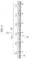
- Fig. 4 shows a part of the section of the composite panel member 52.
- This panel member 52 is produced by welding a plurality of constituent plate members 51a, 51b, 51c, 51d, 51e, 51f (Fig. 4) over the whole peripheries, in succession.
- the plate member 51a is positioned at the front end of the forward area 11F of the side member 11.
- respective thicknesses t1, t2, t3, t4, t5, t6 of the members 51a, 51b, 51c, 51d, 51e, 51f are established so as to gradually change in accordance with the following relationship of: t1 ⁇ t2 ⁇ t3 ⁇ t4 ⁇ t5 ⁇ t6
- the plate member 51f having the largest thickness corresponds to the reinforcement part 11R.
- the forward area 11F of the side member 11 is defined in the following relationship. As shown in Figs. 5A and 5B, when a collision load F is statically exerted to the front end of the forward area 11F obliquely from the front, there is established, as to the maximum value of the sum of a stress of axial-force component (FY/A(y)) and a stress of moment component ( ⁇ FX ⁇ (L-y) ⁇ /Z(y)) both generated in the respective imaginary sections Ia, Ib,.... , Ie (see Fig. 3), a relationship that the maximum value of front part of each imaginary section is nearly equal to that of the rear part of the same imaginary section (front part ⁇ rear part).
- the upper limit of the maximum stress in accordance with the variable plate-thickness structure 50 is established on the basis of the yield strength of the material forming the side member 11, as mentioned above.
- the yield strength ⁇ (y) with respect to the plate members 51a, 51b, 51c, 51d, 51e, 51f, as shown in Fig. 6.
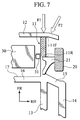
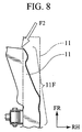
- the front body structure of the first embodiment when a static collision load F2 is exerted on the front end of the side member 11 obliquely from the front as shown in Fig. 7, there are established the above-mentioned relationships among respective properties of the yield strength ⁇ (y), the stress FY/A(y), the stress ⁇ FX ⁇ (L-y) ⁇ . Therefore, if the vehicle has a collision as one automotive dynamic phenomenon, then the front end (input point) of the side member 11 reaches the yielding area of the material to produce a plastic deformation. Consequently, when the collision load F2 is exerted to the side member 11 due to the oblique-and-front collision, the forward area 11F of the side member 11 is not deformed in the mode of Fig.
- the forward area 11F of the side member 11 is subjected to the axial collapse K while being accompanied with a deviation from the root side of the member 11 to the inside (in the width direction of the vehicle) due to the application of a component of the collision load F2 to the member 11, as shown in Fig. 9B.
- the rear end of the forward area 11F of the side member 11 is formed by the reinforcement part 11R for mounting the power unit 30, it is not necessary to reinforce the rear end of the forward area 11F owing to the utilization of the rigidity characteristics of the reinforcement part 11R, whereby it is possible to rationalize the structure of the side member 11 and also possible to make it compact.
- variable plate-thickness structure 50 in the forward area 11F, even if a frontal collision load F1 were applied to the front end of the side member 11 in the axial direction, the axial collapse K would be induced over the whole area of the forward area 11F, whereby the collision energy could be absorbed effectively, as shown in Fig. 9A.
- variable plate-thickness structure 50 of the embodiment allows the frontal collision load F1 and the oblique-and-front collision F2 to produce the axial collapse K in the forward area 11F, it is possible to reduce a dispersion in absorbing the collision energy with respect to an input angle of the collision load F, accomplishing a stable energy absorption as shown in Fig. 10B. Note that the dispersion is often the case with the side member in the earlier technology, as shown in Fig. 10A.
- variable plate-thickness structure 50 is formed by the composite panel member 52 which is obtained by welding the plural plate members 51a, 51b, 51c, 51d, 51e, 51f having different thicknesses t1, t2, t3, t4, t5, t6 in a manner that the thicknesses gradually change, it is possible to control the maximum stress generated in the imaginary sections Ia, Ib, ..., Ie extending in the longitudinal direction of the side member 11 approximately, whereby the collapse K from the front end of the forward area 11F can be induced with no hindrance and it is possible to form the forward area 11F with ease.
- variable plate-thickness structure 50 is provided by changing the sectional dimensions of the forward area 11F in the longitudinal direction of the side member 11, it is possible to easily control the maximum stress generated in the imaginary sections Ia, Ib, ..., Ie when the collision load F is applied to the front end of the side member 11.
- the variable plate-thickness structure 50 facilitates the adjustment of balance in strength, whereby the collapse K at the collision can be induced from the front end of the forward area 11F certainly.
- the number of plate members 51a, ... , 51f it is not limited to the number of this embodiment only. The number may be determined in accordance with the required collapse characteristics of the forward area 11F.
- the present invention is not limited to this embodiment only. Alternatively, it may be established that the maximum stress of the front part of each section is more than or close to that of the rear part of the corresponding section (front part ⁇ rear part).
- Fig. 11 shows the second embodiment of the invention.
- elements similar to those of the first embodiment are indicated with the same reference numerals respectively and their overlapping descriptions are eliminated.
- Fig. 11 is an enlarged sectional view of the forward area of the side member.
- the strength adjusting mechanism of the invention is formed by a variable partition-thickness structure 60 of Fig. 11.
- a plurality of partitions 61a, 61b, 61c, 61d, 61e are arranged in the closed section of the forward area 11F of the side member 11, at appropriate intervals in the longitudinal direction.
- respective thicknesses t1, t2, t3, t4, t5 of the partitions 61a, 61b, 61c, 61d, 61e are established so as to gradually change in the longitudinal direction of the side member 11 with the following relationship of: t1 ⁇ t2 ⁇ t3 ⁇ t4 ⁇ t5
- the partitions 61a, 61b, 61c, 61d, 61e are secured with the inside wall of the side member 11 at the forward area 11F, into one body. Owing to the interposition of the partitions 61a, 61b, 61c, 61d, 61e in the side member 11, the rigidity of the side member 11 can be enhanced at the forward area 11F. Further, by adjusting the plate thicknesses t1, t2, t3, t4, t5 of the partitions 61a, 61b, 61c, 61d, 61e, it is possible to increase the rigidity of the side member 11 at will.
- a plate thickness t of the circumferential wall of the side member 11 is established to be constant over the whole sections of the forward area 11F.
- the maximum stress generated in the imaginary sections succeeding in the longitudinal direction of the forward area 11F when the collision load F is applied to the front end of the side member 11, can be controlled by the formation of the partitions 61a, 61b, 61c, 61d, 61e.
- the variable partition-thickness structure 60 facilitates the adjustment of balance in strength, whereby the collapse K at the collision can be induced from the front end of the forward area 11F certainly, effecting the similar effects to the first embodiment.
- variable partition-thickness structure 60 of this embodiment may be combined with the afore-mentioned variable plate-thickness structure 50 of the first embodiment, providing the strength adjusting mechanism in one modification.
- Figs. 12 and 13 show the third embodiment of the invention.
- elements similar to those of the first embodiment are indicated with the same reference numerals respectively and their overlapping descriptions are eliminated.
- Fig. 12 shows a framework structure on the right side of the front part of the vehicle schematically.
- Fig. 13 is a perspective view of the forward area of the side member.
- the forward area 11F in front of the reinforcement part 11R of the side member 11 is inclined outward in the width direction of the vehicle as directing forward.
- the forward area 11F is also provided with the variable plate-thickness structure 50 of the first embodiment, providing the strength adjusting mechanism.
- respective sections 1 ⁇ to 6 ⁇ are formed to have respective plate thicknesses gradually increased as approaching the reinforcement part 11R.
- the outward inclination of the forward area 11F allows the front end of the side member 11 to be positioned on the outer side in the vehicle body, it is possible to enlarge an input-bearing range established at the vehicle front end, in the width direction of the vehicle.
- Fig. 12 also shows one collision model which is hard to directly exert a collision load F on a straight side member shown with broken lines. While, in the slanted side member 11 (shown with solid lines) of this embodiment, since a component Fn of the collision load F is inputted to the forward area 11F of the side member 11, it is possible to absorb the collision energy appropriately.
- the forward area 11F is inclined from the reinforcement part 11R outward in the width direction of the vehicle, when the side member 11 is subjected to the collision load F as shown in the figure, it is possible to establish a load-transmission route C where the collision load (component) is transmitted to the other reinforcement part (not shown) and the other side member (also not shown) through the mount bracket 31, the power unit 30 and the other mount bracket (not shown), in order. That is, according to the embodiment, it is possible to disperse the collision load F to various components in the front part of the vehicle.
- Figs. 14 to 16 show the fourth embodiment of the present invention. Also in this embodiment, elements similar to those of the first embodiment are indicated with the same reference numerals respectively and their overlapping descriptions are eliminated.
- Fig. 14 is a perspective view of the forward area of the side member of this embodiment.
- Fig. 15 is an enlarged sectional view taken along a line 15-15 of Fig. 14.
- Fig. 16 is a stress-distribution diagram showing the concept of the strength adjusting mechanism of the embodiment.
- the strength adjusting mechanism is formed by a variable sectional-dimension structure 70 where sectional dimensions x, y defining the forward area 11F gradually change in the longitudinal direction of the side member 11, as shown in Fig. 14.
- variable sectional-dimension structure 70 is formed so that, in the forward area 11F of the side member 11, a plate thickness t tapers off to its front end, as shown in Fig. 15. That is, in the forward area 11F, all of the sectional dimensions x, y and the plate thickness t changes in the longitudinal direction of the side member 11 continuously.
- the side member 11 is formed by an extrusion of light metals, such as aluminum alloy, providing the forward area 11F with the above variables x, y, t.
- the front body structure of the embodiment can perform the similar functions to those of the first embodiment. That is, since the sectional dimensions of the forward area 11F are changed in the longitudinal direction of the side member 11, it is possible to easily control the maximum stress generated in the imaginary sections when a collision load is applied to the front end of the side member 11. As the side member 11 of this embodiment is also provided with a sort of variable plate-thickness structure, it facilitates the adjustment of balance in strength. Consequently, at the vehicle collision, it is possible to induce a collapse beginning with the front end of the forward area 11F certainly.
- the forward area 11F of the side member 11 is formed by an extrusion capable of changing the sectional dimensions x, y and the plate thickness t continuously in the longitudinal direction, the extrusion facilitates the adjustment of plate thickness, thereby promoting the rationalization of the structure and also providing the lightweight structure.
- the fourth embodiment owing to the adoption of an extrusion as the strength adjusting mechanism, it is possible to adjust a distribution of plate thickness or sectional dimensions in the longitudinal direction of the forward area of the side member at will and also possible to control changes of the distribution or the sectional dimensions continuously. Therefore, it is possible to control a change in plate thickness with high accuracy and also possible to adjust the maximum stress generated in the imaginary sections extending in the longitudinal direction of the forward area with high accuracy, thereby promoting the rationalization of the structure and also providing the lightweight structure.
- Figs. 17 to 24 show the fifth embodiment of the present invention. Also in this embodiment, elements similar to those of the first embodiment are indicated with the same reference numerals respectively and their overlapping descriptions are eliminated.
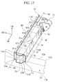
- Fig. 17 is a perspective view of the forward area of the side member of this embodiment.
- Fig. 18 is an enlarged sectional view taken along a line 18-18 of Fig. 17.
- the side member 11 is provided, at its forward area 11F in front of the reinforcement part 11R, with the strength adjusting mechanism by which it is established that the maximum stress generated in the front part of each one of imaginary sections Ia, Ib,.... , Ie extending in the longitudinal direction of the member 11 is less than the maximum stress generated in the rear part of the corresponding section.
- the strength adjusting mechanism is embodied by a variable plate-thickness structure 80 which allows the plate thickness of the forward area 11F to be varied in the longitudinal direction of the side member 11.
- variable plate-thickness structure 80 is formed by a composite panel member 82.
- Fig. 18 shows a part of the section of the composite panel member 82.
- This panel member 82 is produced by welding a plurality of constituent plate members 81a, 81b, 81c, 81d, 81e, 81f (Fig. 18) over the whole peripheries, in succession.
- the plate member 81a is positioned at the front end of the forward area 11F of the side member 11.
- respective thicknesses t1, t2, t3, t4, t5, t6 of the members 81a, 81b, 81c, 81d, 81e, 81f are established so as to gradually change in accordance with the following relationship of: t1> t2> t3>t4> t5> t6
- the plate member 51f having the smallest thickness corresponds to the reinforcement part 11R. Nevertheless, the reinforcement part 11R has enough strength to support the power unit 30 (Fig. 2).
- the forward area 11F of the side member 11 is defined in the following relationship. As shown in Fig. 19, when a collision load F is statically exerted to the front end of the forward area 11F from the front, the upper limit of the maximum stress in accordance with the variable plate-thickness structure 80 is established on the basis of the yield strength of the material forming the side member 11, as mentioned above. As a result, there can be obtained a distribution of the yield strength ⁇ (y) with respect to the plate members 81a, 81b, 81c, 81d, 81e, 81f, as shown in Fig. 20.
- the side member 11 is provided, on its front end, with four flange parts 11c, 11d, 11f, 11e.
- the flange parts 11c, 11d are welded to an upper face 12a of the bumper reinforcement 12 and the lower face 12b, respectively.
- the flange parts 11e, 11f of the side member 11 are welded to the rear face 12c of the bumper reinforcement 12.
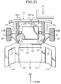
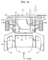
- a collision load F is exerted on the front end of the side member 11 from the front (see Fig. 21)
- a collapse K is firstly produced in the rear part of the forward area 11F, as shown in Fig. 22. Then, the collapse K is continuously induced toward the front part of the side member 11. As a result, the collapse K is transmitted to the front end of the forward area 11F, whereby the absorbing efficiency of the collision energy can be enhanced.
- an axial input Fn acts on the side member 11 on the collision side (right), thereby generating opposing moments Mbmpr in the bumper reinforcement 12 and also a moment Mjnt about the connecting part between the bumper reinforcement 12 and the side member 12 on the non-collision side (left).
- the bumper reinforcement 12 moves backward while maintaining its posture in parallel with the width direction of the vehicle. Consequently, an axial input Fn' is exerted to the side member 11 on the non-collision side (left), thereby accomplishing the load dispersion of the collision effectively.
- the rigidity of the bumper reinforcement 12 itself can be highly maintained to avoid its fracture and further, the joint strength between the bumper reinforcement 12 and the side member 11 can be ensured enough to maintain the constant angle ⁇ .
- the axial input Fn allows the collapse K to be caused from the rear part of the forward area 11F on the collision side and the axial input Fn' allows the collapse K to be caused from the rear part of the forward area 11F on the non-collision side, it is possible to enhance the absorption efficiency of the collision energy even if the vehicle has the offset collision.
- each angle ⁇ becomes a right angle. Accordingly, not to mention a "full-rap" collision, even when the vehicle has the offset collision, the continuous collapse can be effectively produced from the rear part of each forward area 11F, improving the energy-absorption characteristics of the vehicle.
- the upper limit of the maximum stress is established on the basis of the yield strength of the material forming the side member 11.
- the rear part of the forward area 11F having an increased maximum stress firstly reaches the yielding area of the material to produce a plastic deformation. Consequently, at the vehicle collision, it is possible to induce the forward areas' collapse beginning at the rear parts more certainly.
- variable plate-thickness structure 80 is provided by changing the distribution of plate-thickness of the forward area 11F in the longitudinal direction of the side member 11, it is possible to easily control the maximum stress generated in the imaginary sections Ia, Ib, ..., Ie when the collision load F is applied to the front end of the side member 11.
- the variable plate-thickness structure 80 facilitates the adjustment of balance in strength, inducing the collapse K of the forward area 11F beginning at its rear end at the collision more certainly.
- variable plate-thickness structure 80 is formed by the composite panel member 82 which is obtained by welding the plural plate members 81a, 81b, 81c, 81d, 81e, 81f having different thicknesses t1, t2, t3, t4, t5, t6 in a manner that the thicknesses gradually change, it is possible to control the maximum stress generated in the imaginary sections Ia, Ib, ..., Ie extending in the longitudinal direction of the side member 11 approximately, whereby the collapse K beginning at the front end of the forward area 11F can be induced with no hindrance.
- the composite panel member 82 can be simply obtained by welding the plural plate members 81a, 81b, 81c, 81d, 81e, 81f having different thicknesses t1, t2, t3, t4, t5, t6 and it is possible to form the forward area 11F with ease.
- the number of plate members 81a, ..., 81f it is not limited to the number of this embodiment only. The number may be determined in accordance with the required collapse characteristics of the forward area 11F.
- Fig. 25 shows the sixth embodiment of the invention.
- elements similar to those of the first embodiment are indicated with the same reference numerals respectively and their overlapping descriptions are eliminated.
- Fig. 25 is an enlarged sectional view of the forward area of the side member.
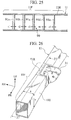
- the strength adjusting mechanism of the invention is formed by a variable partition-thickness structure 90 of Fig. 25.
- a plurality of partitions 91a, 91b, 91c, 91d, 91e are arranged in the closed section of the forward area 11F of the side member 11, at appropriate intervals in the longitudinal direction.
- respective thicknesses t1, t2, t3, t4, t5 of the partitions 91a, 91b, 91c, 91d, 91e are established so as to gradually change in the longitudinal direction of the side member 11 with the following relationship of: t1> t2> t3>t4> t5
- the partitions 91a, 91b, 91c, 91d, 91e are secured with the inside wall of the side member 11 at the forward area 11F, into one body. Owing to the interposition of the partitions 91a, 91b, 91c, 91d, 91e in the side member 11, the rigidity of the side member 11 can be enhanced at the forward area 11F. Further, corresponding to the plate thicknesses t1, t2, t3, t4, t5 of the partitions 91a, 91b, 91c, 91d, 91e, the increasing rate in rigidity is gradually increased as approaching forward.
- a plate thickness t of the circumferential wall of the side member 11 is established to be constant over the whole sections of the forward area 11F.
- the maximum stress generated in the imaginary sections succeeding in the longitudinal direction of the forward area 11F when the collision load F is applied to the front end of the side member 11, can be controlled by the formation of the partitions 91a, 91b, 91c, 91d, 91e.
- the variable partition-thickness structure 90 facilitates the adjustment of balance in strength, whereby the collapse K at the collision can be induced from the front end of the forward area 11F certainly, effecting the similar effects to the first embodiment.
- variable partition-thickness structure 90 of this embodiment may be combined with the afore-mentioned variable plate-thickness structure 80 of the fifth embodiment, providing the strength adjusting mechanism in one modification.
- Figs. 26 to 28 show the seventh embodiment of the present invention. Also in this embodiment, elements similar to those of the first embodiment are indicated with the same reference numerals respectively and their overlapping descriptions are eliminated.
- Fig. 26 is a perspective view of the forward area of the side member of this embodiment.
- Fig. 27 is an enlarged sectional view taken along a line 27-27 of Fig. 26.
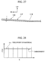
- Fig. 28 is a stress-distribution diagram showing the concept of the strength adjusting mechanism of the embodiment.
- the strength adjusting mechanism is formed by a variable sectional-dimension structure 100 where sectional dimensions x, y defining the forward area 11F gradually increase in the longitudinal direction of the side member 11 as approaching the front end of the side member 11.
- variable sectional-dimension structure 100 is formed so that, in the forward area 11F of the side member 11, a plate thickness t increases as approaching the front end of the member 11, as shown in Fig. 27. That is, in the forward area 11F, all of the sectional dimensions x, y and the plate thickness t changes in the longitudinal direction of the side member 11 continuously.
- the side member 11 is formed by an extrusion of light metals, such as aluminum alloy.
- the front body structure of the embodiment can perform the similar functions to those of the fifth embodiment. That is, since the sectional dimensions of the forward area 11F are changed in the longitudinal direction of the side member 11, it is possible to easily control the maximum stress generated in the imaginary sections when a collision load is applied to the front end of the side member 11. As the side member 11 of this embodiment is also provided with a sort of variable plate-thickness structure, it facilitates the adjustment of balance in strength. Consequently, at the vehicle collision, it is possible to induce a collapse beginning with the front end of the forward area 11F certainly.
- the forward area 11F of the side member 11 is formed by an extrusion capable of changing the sectional dimensions x, y and the plate thickness t continuously in the longitudinal direction, the extrusion facilitates the adjustment of plate thickness, thereby promoting the rationalization of the structure and also providing the lightweight structure.
- the seventh embodiment owing to the adoption of an extrusion as the strength adjusting mechanism, it is possible to adjust a distribution of plate thickness or sectional dimensions in the longitudinal direction of the forward area of the side member at will and also possible to control changes of the distribution or the sectional dimensions continuously. Therefore, it is possible to control a change in plate thickness with high accuracy and also possible to adjust the maximum stress generated in the imaginary sections extending in the longitudinal direction of the forward area with high accuracy, thereby promoting the rationalization of the structure and also providing the lightweight structure.
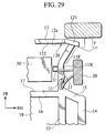
- Fig. 29 to 38 show the eighth embodiment of the front body structure in accordance with the present invention. Also in this embodiment, elements similar to those of the first embodiment are indicated with the same reference numerals respectively and their overlapping descriptions are eliminated.
- Fig. 29 is a plan view of the front body structure.
- the forward area 11F in front of the reinforcement part 11R of the side member 11 is inclined outward in the width direction of the vehicle by a predetermined angle ⁇ as approaching the front end of the side member 11.
- the forward area 11F of the side member 11 is provided with a variable plate-thickness structure 110 (as the strength adjusting mechanism) by which it is established that the maximum stress generated in the front part of each one of imaginary sections Ia, Ib,...., Ie extending in the longitudinal direction of the member 11 is larger than or close to the maximum stress generated in the rear part of the corresponding section.
- the plate thickness of the forward area 11F is changed in the longitudinal direction of the side member 11.
- variable plate-thickness structure 110 is formed by a composite panel member 112.
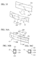
- Fig. 31 shows a part of the section of the composite panel member 112.
- This panel member 112 is produced by welding a plurality of constituent plate members 111a, 111b, 111c, 111d, 111e, 111f (Fig. 31) over the whole peripheries, in succession.
- the plate member 111a is positioned at the front end of the forward area 11F of the side member 11.
- respective thicknesses t1, t2, t3, t4, t5, t6 of the members 111a, 111b, 111c, 111d, 111e, 111f are established so as to gradually change in accordance with the following relationship of: t1 ⁇ t2 ⁇ t3 ⁇ t4 ⁇ t5 ⁇ t6
- the plate member 111f having the largest thickness corresponds to the reinforcement part 11R.
- the forward area 11F of the side member 11 is defined in the following relationship. As shown in Figs. 32A and 32B, when a collision load F is statically exerted to the front end of the forward area 11F from the front, there is established, as to the maximum value of the sum of a stress of axial-force component (FY/A(y)) and a stress of moment component ( ⁇ FX ⁇ (L-y) ⁇ /Z(y)) both generated in the respective imaginary sections Ia, Ib,...., Ie (see Fig. 30), a relationship that the maximum value of front part of each imaginary section is nearly equal to that of the rear part of the same imaginary section (front part ⁇ rear part).
- the upper limit of the maximum stress in accordance with the variable plate-thickness structure 110 is established on the basis of the yield strength of the material forming the side member 11, as mentioned above.
- the yield strength ⁇ (y) with respect to the plate members 111a, 111b, 111c, 111d, 111e, 111f, as shown in Fig. 33.
- the forward area 11F of the embodiment is inclined outward in the width direction of the vehicle. Therefore, if the collision load F is exerted to the forward area 11F from the front, then the side member 11 is collapsed from the front successively, as shown in Figs. 34A, 34B and 34C. With the progress of collapse K, the so-deformed side member 11 interferes with the rear face of the bumper reinforcement 12.
- the bumper reinforcement 12 is provided with a reaction force adjusting mechanism that operates to restrict an increase of a reaction force of the side member 11 when the interference of the side member 11 with the bumper reinforcement 12 advances to a certain extent.
- the reaction force adjusting mechanism includes a changed height part 120 of the bumper reinforcement 12. As shown in Fig.
- the changed height part 120 has an increased-height area 121 formed in the vicinity of a connecting part G of the side member 11 with the bumper reinforcement 12.
- the increased-height area 121 has a height "h1" substantially equal to or more than a height "ho" of a section of the side member 11.
- the changed height part 120 has a reduced-height area 122 arranged inward and apart from the connecting part G by a predetermined distance.
- the reduced-height area 122 has a height "h2" less than the height "ho" of the section of the side member 11.
- the reduced-height area 122 is defined so as to obliquely confront the side face 11b.
- the changed height part 120 defined on the bumper reinforcement 12 may be formed by using a press-forming machine (not shown) utilizing the action of liquid pressure.
- the above reduced-height area 122 is provided by partially depressing both upper face and lower face of the bumper reinforcement 12 having a closed section. Consequently, the increased-height area 121 and the reduced-height area 122 are successively formed on the bumper reinforcement 12, through a step part 123 as the boundary.
- the bumper reinforcement 12 may be constructed by an extrusion of light alloy, as shown in Figs. 36A to 36C.
- the bumper reinforcement 12 is firstly provided, in a closed section thereof, with a pair of partitions 124, by an extruder (not shown).
- an extruder not shown
- upper and lower walls of the bumper reinforcement 12 are partially removed by means of e.g. machining, providing the reduced-height area 122 of Fig. 36C.
- the changed height part 120 may be formed by another "light alloy" extrusion having variable sections (not shown). Note that such an extrusion could be provided by extruding a material through a molding die having the final sectional shape.
- the front body structure of the eighth embodiment when a static collision load F is exerted on the front end of the side member 11 from the front as shown in Fig. 29, there are established the above-mentioned relationships among respective properties of the yield strength ⁇ (y), the stress FY/A(y), the stress ⁇ FX ⁇ (L-y) ⁇ . Therefore, if the vehicle has a collision as one automotive dynamic phenomenon, then the front end (input point) of the side member 11 reaches the yielding area of the material to produce a plastic deformation.
- the forward area 11F of the side member 11 induces a collapse from the front end (as the input point) and subsequently, the collapse is continuously transmitted toward the rear side, whereby a collision energy can be absorbed certainly.
- the forward area 11F is inclined outward in the width direction of the vehicle toward the front end of the side member 11, it is possible to allow the frontal collision to collapse the forward area 11F from its front end continuously, to mention nothing of the oblique-and-front collision.
- the outward inclination of the forward area 11F allows the front end of the side member 11 to be positioned on the outer side in the vehicle body, it is possible to enlarge an input-bearing range established at the vehicle front end, in the width direction of the vehicle.
- the reduced-height area 122 of the changed height part 120 is arranged so as to correspond to the side face (central portion) 11b except the upper and lower ridgelines 11g, 11h of the side member 11, when the side face (central portion) 11b interferes with the reduced-height area 122 with the progress of the collapse K, the forward area 11F is subjected to a deformation beginning at the side face 11b of low rigidity, as shown in Fig. 34C. In this way, since the collapse K can be expedited while restricting the increase of reaction force, it is possible to attain an effective energy absorption.
- Fig. 38 shows a reaction-force characteristics P of the side member 11 in case of adopting the bumper reinforcement 12 having no changed height part and also another reaction-force characteristics Q of the side member 11 in case of adopting the bumper reinforcement 12 formed with the changed height part 120. From the figure, it will be understood that when the interference area between the forward area 11F and the bumper reinforcement 12 increases with the passage of time, a "reaction-force down" area capable of greatly reducing the reaction force can be ensured in the latter part of the collapse in accordance with the reaction-force characteristics Q.
- the changed height part 120 forming the reaction force adjusting mechanism is provided by only changing the sectional heights h1, h2 of the bumper reinforcement 12, it is possible to simplify the whole structure of the reaction force adjusting mechanism.
- variable plate-thickness structure 110 is formed by the composite panel member 112 which is obtained by welding the plural plate members 111a, 111b, 111c, 111d, 111e, 111f having different thicknesses t1, t2, t3, t4, t5, t6 in a manner that the thicknesses gradually change, it is possible to control the maximum stress generated in the imaginary sections Ia, Ib, ..., Ie extending in the longitudinal direction of the side member 11 approximately, whereby the collapse K from the front end of the forward area 11F can be induced with no hindrance and it is possible to form the forward area 11F with ease.
- variable plate-thickness structure 110 is provided by changing the sectional dimensions of the forward area 11F in the longitudinal direction of the side member 11, it is possible to easily control the maximum stress generated in the imaginary sections Ia, Ib, ..., Ie when the collision load F is applied to the front end of the side member 11.
- the variable plate-thickness structure 110 facilitates the adjustment of balance in strength, whereby the collapse K at the collision can be induced from the front end of the forward area 11F certainly.
- the number of plate members 111a, ..., 111f it is not limited to the number of this embodiment only. The number may be determined in accordance with the required collapse characteristics of the forward area 11F.
- the present invention is not limited to this embodiment only. Alternatively, it may be established that the maximum stress of the front part of each section is more than or close to that of the rear part of the corresponding section (front part ⁇ rear part).
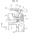
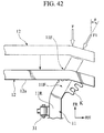
- Figs. 39 to 42 show the ninth embodiment of the present invention. Also in this embodiment, elements similar to those of the first embodiment are indicated with the same reference numerals respectively and their overlapping descriptions are eliminated.
- Fig. 39 is a plan view of the front body structure.
- the bumper reinforcement 12 is provided, on the rear face 12a, with a projection 130 forming the reaction force adjusting mechanism which is similar to the eighth embodiment.
- the bumper reinforcement 12 is formed to have a sectional height "h1" substantially equal to or more than the sectional height "t0" of the side member 12 (see Fig. 30).
- the projection 130 on the bumper reinforcement 12 is arranged apart from the connecting part G by a predetermined distance.
- the projection 130 is formed to have a height "h3" less than the height "h0" of the side member 11.
- the projection 130 is arranged so as to correspond to the side face (central portion) 11b of the forward area 11F of the side member 11 except the upper and lower ridgelines 11g, 11h.
- the projection 130 is shaped to be a channel member having a U-shaped section. Both end flanges 131, 131a of the projection 130 are continuously welded to the rear face 12a of the bumper reinforcement 12, at its intermediate part in the direction of height. Of course, the projection 130 is formed to have enough rigidity to collapse the side member 11 at its interference with the projection 130.
- the forward area 11F firstly interferes with the bumper reinforcement 12 having the large sectional height "h1", causing a collapse K of the whole section including the ridgelines 11c, 11d of the closed-sectional side member 11, as similar to the eighth embodiment.
- the side member 11 is brought into the interference with the projection 130, so that the forward area 11F is subjected to a deformation beginning at the side face 11b of low rigidity.
- the collapse K can be expedited while restricting the increase of reaction force, it is possible to attain an effective energy absorption.
- the bumper reinforcement 12 is formed to have the sectional height "h1" substantially equal to or more than the sectional height "h0" and the projection 130 is fixed on the rear face 12a of the so-formed bumper reinforcement 12, providing the reaction force adjusting mechanism. Therefore, it is possible to simplify the structure of the front body structure without applying a complicated mechanical processing on the bumper reinforcement 12.
Landscapes
- Engineering & Computer Science (AREA)
- Chemical & Material Sciences (AREA)
- Combustion & Propulsion (AREA)
- Transportation (AREA)
- Mechanical Engineering (AREA)
- Body Structure For Vehicles (AREA)
Abstract
Description
Claims (18)
- A front body structure for a vehicle, comprising:a pair of side members (11) arranged on both sides of a front compartment (F·C) of the vehicle to extend in a fore-and-aft direction of the vehicle, the side members (11) each including a reinforcement part (11R) for supporting a vehicle unit component (30); anda strength adjusting mechanism (50, 60, 70, 80, 90, 100, 110) arranged in a forward area (11F) in front of the reinforcement part (11R), for adjusting respective maximum stresses generated in both front part and rear part of each one of imaginary sections (Ia, Ib, ... Ie) continuing in the longitudinal direction of the side member (11).
- The front body structure of claim 1, wherein the strength adjusting mechanism (50, 60, 70, 80, 90, 100, 110) adjusts a strength of the side member (11) so that the maximum stress generated in the front part of each one of imaginary sections (Ia, Ib, ... Ie) continuing in the longitudinal direction of the side member (11) becomes more than or close to the maximum stress generated in the rear part of the each one of imaginary sections (Ia, Ib, ... Ie).
- The front body structure of claim 1, wherein the strength adjusting mechanism (50, 60, 70, 80, 90, 100, 110) adjusts a strength of the side member (11) so that the maximum stress generated in the front part of each one of imaginary sections (Ia, Ib, ... Ie) continuing in the longitudinal direction of the side member (11) becomes less than the maximum stress generated in the rear part of the each one of imaginary sections (Ia, Ib, ... Ie).
- The front body structure of claim 1, wherein
the maximum stress of the strength adjusting mechanism (50, 60, 70, 80, 90, 100, 110) is basically defined by a yield strength of a material forming the side member (11). - The front body structure of claim 1, wherein
the strength adjusting mechanism (50, 70, 80, 100, 110) comprises a variable plate-thickness structure (50, 70, 80, 100, 110) that allows a plate thickness of the side member (11) in the forward area (11F) to change in the longitudinal direction of the side member (11). - The front body structure of claim 5, wherein the variable plate-thickness structure (50, 80) is formed by a composite panel member having a plurality of plate members of different plate thicknesses, welded to each other so that the thicknesses change in a step manner, the composite panel member being arranged so that a direction to change the plate thicknesses coincides with the longitudinal direction of the side member (11).
- The front body structure of claim 1, wherein
the strength adjusting mechanism (60, 90) comprises a variable partition-thickness structure (60, 90) wherein a plurality of partitions (61a, 61b, ... 61e, 91a, 91b, ... 91e) are arranged in a closed section of the forward area (11F) in the longitudinal direction of the side member (11) at appropriate intervals, the partitions having their plate thicknesses changed in the longitudinal direction of the side member (11). - The front body structure of claim 1, wherein
the strength adjusting mechanism (70, 100) comprises a variable sectional-dimension structure that allows sectional dimensions in the forward area (11F) of the side member (11) to change in the longitudinal direction of the side member (11). - The front body structure of claim 1, wherein
the forward area (11F) of the side member (11) is formed by an extrusion whose plate thickness and sectional dimensions are changeable in an extruding direction of the extrusion continuously, the strength adjusting mechanism (70, 100) comprising the extrusion having at least either one of the plate thickness and the sectional dimensions changes in an extruding direction of the extrusion continuously. - The front body structure of claim 1, wherein
the maximum stress defined by the strength adjusting mechanism (50, 60, 70, 80, 90, 100, 110) is established by a value which is calculated on the assumption that an oblique input acts on the front end of the side member (11) statically and also calculated on the consideration of both a stress of axial-force component and a stress of moment component both generated in the respective imaginary sections (Ia, Ib, ... Ie) continuing in the longitudinal direction of the forward area (11F). - The front body structure of claim 1, wherein
the forward areas (11F) of the side members (11) are formed straightly in the fore-and-aft direction of the vehicle and arranged in parallel with each other. - The front body structure of claim 2, wherein
the forward areas (11F) of the side members (11) are formed so as to incline outward in a width direction of the vehicle toward the front of the vehicle. - The front body structure of claim 1, further comprising a bumper reinforcement (12) extending in a width direction of the vehicle and connected to the side members (11), the bumper reinforcement (12) formed to have a closed section and it is established that:a section modulus "Z" of the second moment of area of the closed-sectional bumper reinforcement (12) becomes more than the product of a maximum reaction force "Fmax" when the front part of the side member (11) collapses multiplied by the quotient that a span "L" of the forward area (11F) divided by a yield stress "σ y- bmpr" of constituent materials of the bumper reinforcement (12), (Z > Fmax × L / σ y- bmpr ); anda strength "Sjoint" of a joint part of the bumper reinforcement (12) becomes more than the product of the maximum reaction force "Fmax" multiplied by the span "L", ( Sjoint > L × Fmax).
- The front body structure of claim 12, further comprising a reaction force adjusting mechanism (120) arranged, in a width direction of the vehicle, on the inside of a connecting part of the bumper reinforcement (12) with each of the side members (11) to restrict an increase of a reaction force of the side member (11) when the side member (11) interferes with the bumper reinforcement (12) since a front collision load causes the side member (11) to collapse from a front end thereof successively.
- The front body structure of claim 14, wherein the reaction force adjusting mechanism (120) comprises the bumper reinforcement (12) including:an increased-height area (121) formed in the vicinity of the connecting part with a height substantially equal to or more than a height of a section of the side member (11); anda reduced-height area (122) inward formed apart from the connecting part by a predetermined distance with a height less than the height of the section of the side member (11), the reduced-height area obliquely confronting the side face of the forward area (11F) of the side member (11) but upper and lower ridgelines thereof.
- The front body structure of claim 14, wherein the reaction force adjusting mechanism (120) comprises:the bumper reinforcement (12) formed to have a height substantially equal to or more than a height of a section of the side member (11); anda projection (130) formed on a rear face of the bumper reinforcement (12) apart from the connecting part by a predetermined distance, to have a height less than the height of the section of the side member (11), the projection obliquely confronting the side face of the forward area (11F) of the side member (11) but upper and lower ridgelines thereof.
- A front body structure for a vehicle, comprising:a pair of side members (11) arranged on both sides of a front compartment (F·C) of the vehicle to extend in a fore-and-aft direction of the vehicle, the side members (11) each including a reinforcement part (11R) for supporting a vehicle unit component (30); anda strength adjusting mechanism (50, 60, 70, 80, 90, 100, 110) arranged in a forward area (11F) in front of the reinforcement part (11R), for adjusting a strength of the side member (11) so that the maximum stress generated in the front part of each one of imaginary sections (Ia, Ib, ... Ie) continuing in the longitudinal direction of the side member (11) becomes more than or close to the maximum stress generated in the rear part of the each one of imaginary sections (Ia, Ib, ... Ie).
- A front body structure for a vehicle, comprising:a pair of side members (11) arranged on both sides of a front compartment (F · C) of the vehicle to extend in a fore-and-aft direction of the vehicle, each of the side members (11) including a reinforcement part (11R) for supporting a vehicle unit component (30); andmeans for adjusting a strength (50, 60, 70, 80, 90, 100, 110) of the side member (11) so that a maximum stress generated in a front part of each one of imaginary sections (Ia, Ib, ... Ie) continuing in the longitudinal direction of the side member (11) becomes more than or close to a maximum stress generated in a rear part of the each one of imaginary sections (Ia, Ib, ... Ie), the means being arranged in a forward area (11F) in front of the reinforcement part (11R) of each of the side members (11).
Applications Claiming Priority (6)
| Application Number | Priority Date | Filing Date | Title |
|---|---|---|---|
| JP2001347573A JP3613229B2 (en) | 2001-11-13 | 2001-11-13 | Body front structure |
| JP2001347573 | 2001-11-13 | ||
| JP2001371704 | 2001-12-05 | ||
| JP2001371738 | 2001-12-05 | ||
| JP2001371738A JP3572459B2 (en) | 2001-12-05 | 2001-12-05 | Body front structure |
| JP2001371704A JP3632654B2 (en) | 2001-12-05 | 2001-12-05 | Body front structure |
Publications (3)
| Publication Number | Publication Date |
|---|---|
| EP1325859A2 true EP1325859A2 (en) | 2003-07-09 |
| EP1325859A3 EP1325859A3 (en) | 2004-03-31 |
| EP1325859B1 EP1325859B1 (en) | 2017-03-22 |
Family
ID=27347813
Family Applications (1)
| Application Number | Title | Priority Date | Filing Date |
|---|---|---|---|
| EP02023487.8A Expired - Lifetime EP1325859B1 (en) | 2001-11-13 | 2002-10-21 | Front body structure for vehicle enhancing the absorbing efficiency of the energy in case of a collision |
Country Status (2)
| Country | Link |
|---|---|
| US (1) | US6893078B2 (en) |
| EP (1) | EP1325859B1 (en) |
Cited By (1)
| Publication number | Priority date | Publication date | Assignee | Title |
|---|---|---|---|---|
| DE202005005488U1 (en) * | 2005-04-07 | 2006-09-07 | Dura Automotive Gmbh | Device for retaining on the bumper of the vehicle has a connecting part fixable at the vehicle frame whereby the deformation pipe in the deformation zone exhibits a continuously reducing wall thickness |
Families Citing this family (45)
| Publication number | Priority date | Publication date | Assignee | Title |
|---|---|---|---|---|
| US6606413B1 (en) * | 1998-06-01 | 2003-08-12 | Trestle Acquisition Corp. | Compression packaged image transmission for telemicroscopy |
| US20040083085A1 (en) * | 1998-06-01 | 2004-04-29 | Zeineh Jack A. | Integrated virtual slide and live microscope system |
| DE10254693A1 (en) * | 2002-11-23 | 2004-06-17 | Daimlerchrysler Ag | Front-end structure |
| US7083223B2 (en) * | 2002-12-13 | 2006-08-01 | Volvo Last Vagnar Ab | Vehicle cab |
| EP1440867B1 (en) * | 2003-01-24 | 2006-08-09 | Ford Global Technologies, Inc. | Structural design component for automotive vehicles |
| US6994350B2 (en) * | 2003-03-28 | 2006-02-07 | General Motors Corporation | Crush zone and method for introducing crush zone into vehicle structure |
| US7407221B2 (en) * | 2003-11-24 | 2008-08-05 | L&W Engineering Incorporated | Support structures using tubes having variable wall thicknesses |
| JP4376042B2 (en) * | 2003-12-01 | 2009-12-02 | 本田技研工業株式会社 | Body frame structure |
| US7066509B2 (en) * | 2004-02-17 | 2006-06-27 | Benteler Automotive Corporation | Energy absorption impact system and method for vehicle bumpers and the like |
| JP4647371B2 (en) * | 2004-05-27 | 2011-03-09 | 本田技研工業株式会社 | Body strength adjustment device |
| JP2006015859A (en) * | 2004-07-01 | 2006-01-19 | Nissan Motor Co Ltd | Front body structure of the vehicle |
| US7380830B2 (en) * | 2005-02-03 | 2008-06-03 | Honda Motor Co., Ltd. | Vehicle front body structure |
| SE529105C2 (en) * | 2005-09-23 | 2007-05-02 | Gestamp Hardtech Ab | Impact box and way to attach a bumper beam |
| DE102006024623B4 (en) * | 2006-05-26 | 2011-06-16 | Daimler Ag | Automotive bodyshell |
| US7651155B2 (en) * | 2006-11-03 | 2010-01-26 | Gm Global Technology Operations, Inc. | Progressive energy absorber |
| JP4186125B2 (en) * | 2006-11-27 | 2008-11-26 | いすゞ自動車株式会社 | Vehicle front structure |
| US7695052B2 (en) * | 2007-03-30 | 2010-04-13 | Ford Global Technologies, Llc | Front rail having controlled thickness for energy absorption |
| JP5201864B2 (en) * | 2007-03-30 | 2013-06-05 | 三菱自動車工業株式会社 | Body structure |
| FR2915451B1 (en) * | 2007-04-26 | 2009-10-09 | Vallourec Vitry | PROLONGED WITH PERFECTED SUPPORT. |
| JP5029328B2 (en) * | 2007-12-05 | 2012-09-19 | マツダ株式会社 | Front body structure of automobile |
| JP5248852B2 (en) * | 2007-12-27 | 2013-07-31 | ヤマハ発動機株式会社 | Vibration damping device for car body |
| DE102009008674B4 (en) * | 2009-02-12 | 2018-05-24 | Audi Ag | Body structure of a vehicle |
| US8419116B2 (en) | 2010-07-08 | 2013-04-16 | Honda Motor Co., Ltd. | Vehicle frame assembly |
| FR2962390A1 (en) * | 2010-07-12 | 2012-01-13 | Citi Technologies | Shock absorber i.e. bumper, for use in automobile, has cells delimited by side walls and internal ribs forming body to ensure absorption of shocks along main direction and extrusion direction perpendicular to main direction |
| GB2488096A (en) * | 2011-01-14 | 2012-08-22 | Aston Martin Lagonda Ltd | Crash load absorption structures for motor vehicles |
| US8414025B2 (en) | 2011-03-16 | 2013-04-09 | GM Global Technology Operations LLC | Energy-absorbing device for a vehicle |
| US8668247B2 (en) * | 2012-04-23 | 2014-03-11 | GM Global Technology Operations LLC | Magnesium-composite structures with enhanced design |
| ITBO20120271A1 (en) * | 2012-05-16 | 2013-11-17 | Ferrari Spa | COLLASSABLE STRIP WITH CONTROLLED DEFORMATION FOR THE FRAME OF A ROAD VEHICLE |
| WO2014066275A1 (en) | 2012-10-22 | 2014-05-01 | Honda Motor Co., Ltd. | Front subframe for a narrow offset collision |
| US8632121B1 (en) * | 2012-11-14 | 2014-01-21 | Ford Global Technologies, Llc | Pole impact protection system |
| JP5637203B2 (en) * | 2012-12-04 | 2014-12-10 | トヨタ自動車株式会社 | Body front structure |
| US9403498B2 (en) | 2013-03-20 | 2016-08-02 | Shiloh Industries, Inc. | Energy absorbing assembly for vehicle |
| DE102013209971A1 (en) * | 2013-05-28 | 2014-12-04 | Bayerische Motoren Werke Aktiengesellschaft | Body structure support for a motor vehicle |
| DE102014206610A1 (en) * | 2014-04-04 | 2015-10-08 | Bayerische Motoren Werke Aktiengesellschaft | Composite structural body of fiber composite material for a motor vehicle and motor vehicle with such a body structure support |
| KR101664048B1 (en) * | 2014-11-10 | 2016-10-24 | 현대자동차 주식회사 | Front side member for vehicle |
| US9580106B2 (en) * | 2015-06-26 | 2017-02-28 | GM Global Technology Operations LLC | Automotive frame rail reinforcing member to manage an offset, frontal applied load |
| KR101714200B1 (en) * | 2015-08-28 | 2017-03-08 | 현대자동차주식회사 | Underbody structure for vehicle |
| US9643651B2 (en) * | 2015-08-28 | 2017-05-09 | Honda Motor Co., Ltd. | Casting, hollow interconnecting member for connecting vehicular frame members, and vehicular frame assembly including hollow interconnecting member |
| WO2017098293A1 (en) * | 2015-12-09 | 2017-06-15 | Arcelormittal | Vehicle front body structure and method for manufacturing thereof |
| WO2017098306A1 (en) * | 2015-12-09 | 2017-06-15 | Arcelormittal | Vehicle rear body structure and method for manufacturing thereof |
| US10155542B2 (en) * | 2016-01-22 | 2018-12-18 | Ford Global Technologies, Llc | Stepped honeycomb rocker insert |
| JP6358300B2 (en) * | 2016-09-06 | 2018-07-18 | マツダ株式会社 | Rear body structure of the vehicle |
| GB201820560D0 (en) | 2018-12-17 | 2019-01-30 | Aston Martin Lagonda Ltd | Assemblies for engines |
| EP4110654A4 (en) * | 2020-02-27 | 2024-04-17 | Tesseract Structural Innovations, Inc. | MULTI-LAYER UNIFORM DELAY UNIT |
| US11713083B2 (en) * | 2021-06-24 | 2023-08-01 | Volvo Car Corporation | Subframe assembly for a vehicle utilizing scaleable multi-cell extruded siderail members |
Family Cites Families (30)
| Publication number | Priority date | Publication date | Assignee | Title |
|---|---|---|---|---|
| US3831997A (en) * | 1973-03-22 | 1974-08-27 | Ford Motor Co | Controlled collapse vehicle front end structure |
| DE2636655A1 (en) * | 1976-08-14 | 1978-02-16 | Daimler Benz Ag | HOLLOW BEAM FOR VEHICLES AND METHOD FOR ITS MANUFACTURING |
| JPS59190060A (en) * | 1983-04-13 | 1984-10-27 | Honda Motor Co Ltd | Body of car |
| DE3432603A1 (en) | 1984-08-31 | 1986-03-13 | Heinrich-Hertz-Institut für Nachrichtentechnik Berlin GmbH, 1000 Berlin | SEMICONDUCTOR COMPONENT THAT HAS A LAYER OF TRANSPARENT, N-CONDUCTIVE MATERIAL, AND USE OF SUCH COMPONENTS |
| JPS61287871A (en) * | 1985-06-17 | 1986-12-18 | Toyota Motor Corp | Side member for automobile |
| JP2529939B2 (en) | 1985-08-19 | 1996-09-04 | 昭和電工建材 株式会社 | Packing method for plate volume stack block |
| JPH0791260B2 (en) | 1986-12-27 | 1995-10-04 | 第一製薬株式会社 | Guanidine derivative and its salt |
| JPH0450083A (en) | 1990-06-15 | 1992-02-19 | Toyota Motor Corp | Front side member structure for car body |
| JPH05139242A (en) | 1991-11-19 | 1993-06-08 | Toyota Motor Corp | Body front part structure |
| JP3144054B2 (en) * | 1992-05-28 | 2001-03-07 | 株式会社豊田自動織機製作所 | Energy absorbing material |
| JPH07101354A (en) | 1993-10-05 | 1995-04-18 | Isuzu Motors Ltd | Vehicle side member |
| JPH07228267A (en) | 1994-02-17 | 1995-08-29 | Mitsubishi Motors Corp | Strength member structure of car body |
| US5431445A (en) * | 1994-11-28 | 1995-07-11 | Ford Motor Company | Asymmetrical beam structure for a vehicle |
| US5913565A (en) * | 1995-09-22 | 1999-06-22 | Nissan Motor | Vehicle member |
| SE505142C2 (en) * | 1995-10-20 | 1997-06-30 | Volvo Ab | Box beam in a vehicle |
| JP3370837B2 (en) | 1995-11-17 | 2003-01-27 | 日野自動車株式会社 | Bumper structure |
| US5876078A (en) * | 1997-01-21 | 1999-03-02 | Ford Global Technologies, Inc. | Bumper and front rail assembly for vehicle |
| JP3333720B2 (en) | 1997-09-02 | 2002-10-15 | 本田技研工業株式会社 | Aluminum alloy hollow frame member for body frame |
| US6099071A (en) * | 1997-09-02 | 2000-08-08 | Honda Giken Kogyo Kabushiki Kaisha | Hollow frame member of aluminum alloy for vehicle body frame |
| JP3470033B2 (en) * | 1998-01-22 | 2003-11-25 | 本田技研工業株式会社 | Car body frame structure |
| JP3690459B2 (en) | 1998-03-10 | 2005-08-31 | 日産自動車株式会社 | Front side member with arch-shaped part |
| US6193303B1 (en) * | 1998-04-03 | 2001-02-27 | Honda Giken Kogyo Kabushiki Kaisha | Control device for controlling rigidity and deformation of car body |
| JP3771721B2 (en) | 1998-07-24 | 2006-04-26 | 富士重工業株式会社 | Front body structure of the vehicle |
| JP2000053019A (en) | 1998-08-17 | 2000-02-22 | Honda Motor Co Ltd | Car body structure |
| ATE247017T1 (en) * | 1998-11-26 | 2003-08-15 | Lotus Car | DEFORMABLE SUPPORTS FOR VEHICLES |
| JP3688526B2 (en) | 1999-08-26 | 2005-08-31 | 本田技研工業株式会社 | Vehicle front structure |
| JP2001063495A (en) | 1999-08-26 | 2001-03-13 | Aisin Keikinzoku Co Ltd | Vehicle bumper device |
| JP3598917B2 (en) | 1999-11-30 | 2004-12-08 | トヨタ自動車株式会社 | Car front side member |
| US6293587B1 (en) * | 2000-03-17 | 2001-09-25 | Dana Corporation | Vehicle body and frame assembly including energy absorbing structure |
| US6655728B2 (en) * | 2000-04-25 | 2003-12-02 | Nissan Motor Co., Ltd. | Body structure of vehicle |
-
2002
- 2002-10-21 EP EP02023487.8A patent/EP1325859B1/en not_active Expired - Lifetime
- 2002-11-04 US US10/286,909 patent/US6893078B2/en not_active Expired - Lifetime
Cited By (1)
| Publication number | Priority date | Publication date | Assignee | Title |
|---|---|---|---|---|
| DE202005005488U1 (en) * | 2005-04-07 | 2006-09-07 | Dura Automotive Gmbh | Device for retaining on the bumper of the vehicle has a connecting part fixable at the vehicle frame whereby the deformation pipe in the deformation zone exhibits a continuously reducing wall thickness |
Also Published As
| Publication number | Publication date |
|---|---|
| EP1325859B1 (en) | 2017-03-22 |
| US6893078B2 (en) | 2005-05-17 |
| US20030090127A1 (en) | 2003-05-15 |
| EP1325859A3 (en) | 2004-03-31 |
Similar Documents
| Publication | Publication Date | Title |
|---|---|---|
| US6893078B2 (en) | Front body structure for vehicle | |
| US5868457A (en) | Structural member of vehicle body | |
| JP5967292B2 (en) | Vehicle front structure | |
| JP6070821B2 (en) | Vehicle front structure | |
| JP3828329B2 (en) | Auto body structure | |
| JP5975168B2 (en) | Vehicle front structure | |
| US6655728B2 (en) | Body structure of vehicle | |
| JP6315292B2 (en) | Vehicle frame structure | |
| JP7354757B2 (en) | Vehicle front body structure | |
| EP1829756B1 (en) | Vehicular hood structure and vehicle body front portion structure | |
| JP7318478B2 (en) | Vehicle front body structure | |
| US7275764B2 (en) | Vehicle occupant knee protection device | |
| JP6399073B2 (en) | Vehicle shock absorption structure | |
| EP4647323A1 (en) | Frame member for vehicle and vehicle-body front structure | |
| JP3632654B2 (en) | Body front structure | |
| JP2001301656A (en) | Car body structure | |
| JP2003291755A (en) | Collision energy absorbing element | |
| JP2003095135A (en) | Car body front structure | |
| JP3572459B2 (en) | Body front structure | |
| JP6565291B2 (en) | Shock absorbing member, vehicle body and shock absorbing method | |
| JP2009248602A (en) | Vehicular bumper mounting structure | |
| JP3613229B2 (en) | Body front structure | |
| JP3591508B2 (en) | Body front structure | |
| JPH115564A (en) | Vehicle side member structure | |
| JP7152292B2 (en) | vehicle front structure |
Legal Events
| Date | Code | Title | Description |
|---|---|---|---|
| PUAI | Public reference made under article 153(3) epc to a published international application that has entered the european phase |
Free format text: ORIGINAL CODE: 0009012 |
|
| 17P | Request for examination filed |
Effective date: 20021021 |
|
| AK | Designated contracting states |
Designated state(s): AT BE BG CH CY CZ DE DK EE ES FI FR GB GR IE IT LI LU MC NL PT SE SK TR |
|
| AX | Request for extension of the european patent |
Extension state: AL LT LV MK RO SI |
|
| PUAL | Search report despatched |
Free format text: ORIGINAL CODE: 0009013 |
|
| AK | Designated contracting states |
Kind code of ref document: A3 Designated state(s): AT BE BG CH CY CZ DE DK EE ES FI FR GB GR IE IT LI LU MC NL PT SE SK TR |
|
| AX | Request for extension of the european patent |
Extension state: AL LT LV MK RO SI |
|
| AKX | Designation fees paid |
Designated state(s): DE FR GB |
|
| GRAP | Despatch of communication of intention to grant a patent |
Free format text: ORIGINAL CODE: EPIDOSNIGR1 |
|
| INTG | Intention to grant announced |
Effective date: 20161121 |
|
| GRAS | Grant fee paid |
Free format text: ORIGINAL CODE: EPIDOSNIGR3 |
|
| GRAA | (expected) grant |
Free format text: ORIGINAL CODE: 0009210 |
|
| AK | Designated contracting states |
Kind code of ref document: B1 Designated state(s): DE FR GB |
|
| REG | Reference to a national code |
Ref country code: GB Ref legal event code: FG4D |
|
| REG | Reference to a national code |
Ref country code: DE Ref legal event code: R096 Ref document number: 60248745 Country of ref document: DE |
|
| REG | Reference to a national code |
Ref country code: FR Ref legal event code: PLFP Year of fee payment: 16 |
|
| REG | Reference to a national code |
Ref country code: DE Ref legal event code: R097 Ref document number: 60248745 Country of ref document: DE |
|
| PLBE | No opposition filed within time limit |
Free format text: ORIGINAL CODE: 0009261 |
|
| STAA | Information on the status of an ep patent application or granted ep patent |
Free format text: STATUS: NO OPPOSITION FILED WITHIN TIME LIMIT |
|
| 26N | No opposition filed |
Effective date: 20180102 |
|
| REG | Reference to a national code |
Ref country code: FR Ref legal event code: PLFP Year of fee payment: 17 |
|
| PGFP | Annual fee paid to national office [announced via postgrant information from national office to epo] |
Ref country code: FR Payment date: 20210913 Year of fee payment: 20 |
|
| PGFP | Annual fee paid to national office [announced via postgrant information from national office to epo] |
Ref country code: GB Payment date: 20210915 Year of fee payment: 20 |
|
| PGFP | Annual fee paid to national office [announced via postgrant information from national office to epo] |
Ref country code: DE Payment date: 20210908 Year of fee payment: 20 |
|
| REG | Reference to a national code |
Ref country code: DE Ref legal event code: R071 Ref document number: 60248745 Country of ref document: DE |
|
| REG | Reference to a national code |
Ref country code: GB Ref legal event code: PE20 Expiry date: 20221020 |
|
| PG25 | Lapsed in a contracting state [announced via postgrant information from national office to epo] |
Ref country code: GB Free format text: LAPSE BECAUSE OF EXPIRATION OF PROTECTION Effective date: 20221020 |