EP1325162B1 - Vorrichtung zum induktiven aufheizen von werkstücken - Google Patents
Vorrichtung zum induktiven aufheizen von werkstücken Download PDFInfo
- Publication number
- EP1325162B1 EP1325162B1 EP01969464A EP01969464A EP1325162B1 EP 1325162 B1 EP1325162 B1 EP 1325162B1 EP 01969464 A EP01969464 A EP 01969464A EP 01969464 A EP01969464 A EP 01969464A EP 1325162 B1 EP1325162 B1 EP 1325162B1
- Authority
- EP
- European Patent Office
- Prior art keywords
- coil cores
- coil
- air gap
- workpiece
- pole faces
- Prior art date
- Legal status (The legal status is an assumption and is not a legal conclusion. Google has not performed a legal analysis and makes no representation as to the accuracy of the status listed.)
- Expired - Lifetime
Links
- 238000010438 heat treatment Methods 0.000 title claims abstract description 16
- 239000000463 material Substances 0.000 claims abstract description 5
- 239000004020 conductor Substances 0.000 claims description 5
- 239000000696 magnetic material Substances 0.000 claims description 3
- CWYNVVGOOAEACU-UHFFFAOYSA-N Fe2+ Chemical compound [Fe+2] CWYNVVGOOAEACU-UHFFFAOYSA-N 0.000 claims description 2
- 230000006698 induction Effects 0.000 description 12
- 230000001939 inductive effect Effects 0.000 description 5
- 238000010586 diagram Methods 0.000 description 3
- 230000006978 adaptation Effects 0.000 description 2
- 238000000034 method Methods 0.000 description 2
- 230000008569 process Effects 0.000 description 2
- 230000009467 reduction Effects 0.000 description 2
- 230000009471 action Effects 0.000 description 1
- 238000003491 array Methods 0.000 description 1
- 230000008901 benefit Effects 0.000 description 1
- 230000008859 change Effects 0.000 description 1
- 238000010276 construction Methods 0.000 description 1
- 238000001816 cooling Methods 0.000 description 1
- 230000008878 coupling Effects 0.000 description 1
- 238000010168 coupling process Methods 0.000 description 1
- 238000005859 coupling reaction Methods 0.000 description 1
- 230000001419 dependent effect Effects 0.000 description 1
- 238000011161 development Methods 0.000 description 1
- 230000018109 developmental process Effects 0.000 description 1
- 230000002500 effect on skin Effects 0.000 description 1
- 230000005684 electric field Effects 0.000 description 1
- 230000006872 improvement Effects 0.000 description 1
- 239000012212 insulator Substances 0.000 description 1
- 230000002441 reversible effect Effects 0.000 description 1
- 230000008719 thickening Effects 0.000 description 1
- 238000010792 warming Methods 0.000 description 1
- 238000004804 winding Methods 0.000 description 1
Images


Classifications
-
- C—CHEMISTRY; METALLURGY
- C21—METALLURGY OF IRON
- C21D—MODIFYING THE PHYSICAL STRUCTURE OF FERROUS METALS; GENERAL DEVICES FOR HEAT TREATMENT OF FERROUS OR NON-FERROUS METALS OR ALLOYS; MAKING METAL MALLEABLE, e.g. BY DECARBURISATION OR TEMPERING
- C21D1/00—General methods or devices for heat treatment, e.g. annealing, hardening, quenching or tempering
- C21D1/34—Methods of heating
- C21D1/42—Induction heating
-
- B—PERFORMING OPERATIONS; TRANSPORTING
- B23—MACHINE TOOLS; METAL-WORKING NOT OTHERWISE PROVIDED FOR
- B23P—METAL-WORKING NOT OTHERWISE PROVIDED FOR; COMBINED OPERATIONS; UNIVERSAL MACHINE TOOLS
- B23P11/00—Connecting or disconnecting metal parts or objects by metal-working techniques not otherwise provided for
- B23P11/02—Connecting or disconnecting metal parts or objects by metal-working techniques not otherwise provided for by first expanding and then shrinking or vice versa, e.g. by using pressure fluids; by making force fits
- B23P11/025—Connecting or disconnecting metal parts or objects by metal-working techniques not otherwise provided for by first expanding and then shrinking or vice versa, e.g. by using pressure fluids; by making force fits by using heat or cold
- B23P11/027—Connecting or disconnecting metal parts or objects by metal-working techniques not otherwise provided for by first expanding and then shrinking or vice versa, e.g. by using pressure fluids; by making force fits by using heat or cold for mounting tools in tool holders
-
- C—CHEMISTRY; METALLURGY
- C21—METALLURGY OF IRON
- C21D—MODIFYING THE PHYSICAL STRUCTURE OF FERROUS METALS; GENERAL DEVICES FOR HEAT TREATMENT OF FERROUS OR NON-FERROUS METALS OR ALLOYS; MAKING METAL MALLEABLE, e.g. BY DECARBURISATION OR TEMPERING
- C21D1/00—General methods or devices for heat treatment, e.g. annealing, hardening, quenching or tempering
- C21D1/06—Surface hardening
- C21D1/09—Surface hardening by direct application of electrical or wave energy; by particle radiation
- C21D1/10—Surface hardening by direct application of electrical or wave energy; by particle radiation by electric induction
-
- C—CHEMISTRY; METALLURGY
- C21—METALLURGY OF IRON
- C21D—MODIFYING THE PHYSICAL STRUCTURE OF FERROUS METALS; GENERAL DEVICES FOR HEAT TREATMENT OF FERROUS OR NON-FERROUS METALS OR ALLOYS; MAKING METAL MALLEABLE, e.g. BY DECARBURISATION OR TEMPERING
- C21D9/00—Heat treatment, e.g. annealing, hardening, quenching or tempering, adapted for particular articles; Furnaces therefor
- C21D9/08—Heat treatment, e.g. annealing, hardening, quenching or tempering, adapted for particular articles; Furnaces therefor for tubular bodies or pipes
-
- Y—GENERAL TAGGING OF NEW TECHNOLOGICAL DEVELOPMENTS; GENERAL TAGGING OF CROSS-SECTIONAL TECHNOLOGIES SPANNING OVER SEVERAL SECTIONS OF THE IPC; TECHNICAL SUBJECTS COVERED BY FORMER USPC CROSS-REFERENCE ART COLLECTIONS [XRACs] AND DIGESTS
- Y02—TECHNOLOGIES OR APPLICATIONS FOR MITIGATION OR ADAPTATION AGAINST CLIMATE CHANGE
- Y02P—CLIMATE CHANGE MITIGATION TECHNOLOGIES IN THE PRODUCTION OR PROCESSING OF GOODS
- Y02P10/00—Technologies related to metal processing
- Y02P10/25—Process efficiency
Definitions
- the invention relates to a device for inductive heating of a rotationally symmetrical Workpiece part of an electrically conductive material existing workpiece with a workpiece on the circumference at least partially comprehensive, acted upon by a high-frequency alternating current Coil assembly.
- a tool holder formed sleeve-shaped workpiece section enlarging the sleeve diameter so that a tool with its shaft in introduced the enlarged recording and then by cooling there can be shrunk.
- the plug-in tool can
- the tool holder are re-tensioned by heating.
- the Induction coil is designed there as a ring or cylindrical coil, which before the Heating process coaxially pushed onto the rotationally symmetrical workpiece part becomes. The latter is possible only if the contemplatspannende Tool is not extended at its over the shaft protruding part. But there are tools that have a thickening on their shaft. For these applications, the known annular induction coils not suitable.
- WO-A-98 52 385 and EP-A-776 146 describe around a rotationally symmetrical piece of work in pairs opposite to arranged inductors with U-shaped Coil cores.
- the invention is based on the object, a device for inductive heating of workpieces to develop, which also for complicated designed, provided with thickened parts is suitable.
- the solution of the invention is based on the idea that for heating of workpieces with variable axial contour a divisible coil arrangement is required.
- the coil assembly at least two by a in his adjustable air gap separate, each at least one coil having supporting coil cores made of magnetizable material, and that the heated workpiece part can be inserted into the air gap.
- the pole faces the bobbins carrying the coils are above each other across the air gap facing while the coils producing one at the respective facing pole faces gleichpoligen or gegenpoligen alternating magnetic field can be acted upon by high-frequency alternating current.
- the invention provides that the facing coil cores have a U-shaped configuration, wherein on each spool core at least one spool is arranged and the free ends of the U-legs of the coil core to form the air gap facing each other.
- the free pole faces of the U-legs of the coil cores are formed in adaptation to the outer contour of the workpiece to be heated part obliquely and in pairs include an angle open toward the air gap.
- the coils are arranged on the coil cores so with alternating current of the same frequency and the same or unequal phase acted upon, that the mutually facing free ends of the coil cores are poled homopolar or opposite polarity.
- the invention proposes that the coils on the two coil cores alternating at predetermined, optionally variable time intervals subjected to in-phase and out-of-phase alternating currents become.
- a preferred application of the invention provides that the workpiece at least in the area of the workpiece part to be heated as a sleeve-shaped Tool holder for the thermal shrinking and shrinking of a cylindrical tool shank is formed.
- the workpiece at least in the area of aufraceenden workpiece part of an electrically conductive and at the same time soft magnetic material, preferably made of a ferrous material consists.
- a further improvement of the air gap losses is achieved when the to be heated workpiece part facing pole faces of the coil cores at least partially coated with a Isalolator Anlagen.
- the coil cores in the area of the insulator layer against the surface the workpiece to be heated while maintaining a small Air gaps are struck.
- the shift can also be automated by that the coils on the coil cores with a DC component under construction one of the coil cores against the force of at least one spring from each other repulsive or attractive force can be acted upon.
- the positioning can be DC powered and the inductive heating time separated while in the latter case creating an attractive force the positioning and heating simultaneously with a DC and an alternating current component takes place.
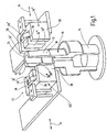
- the shrinking device shown in Fig. 1 is for reversible thermal Clamping cylindrical tools in a chuck 10 determined.
- the chuck 10 has an open at one end Sleeve section 12 for frictionally receiving the cylindrical shaft a tool, not shown.
- the chuck 10 is shown in the Embodiment designed as an adapter, which at its rear End designed as a hollow shaft coupling element 14 for the Connection to a not shown, fast rotating machine spindle having.
- the sleeve portion 12 has a receiving bore 16 and a frustoconical surface 18 on. At the end of the chuck is through a circumferential annular surface 20 limited.
- the diameter of the mounting hole 16 indicates at ambient temperature against the clamped Tool shank undersize on. The clamping and unclamping of the tool is therefore only at elevated temperature of the sleeve section 12 to about 450 ° C possible.
- the heating of the sleeve section 12 takes place by means of a two-part Coil assembly 22 consisting of two adjustable by one in its width Air gap 24 separate coil cores 26 ', 26 "of soft magnetic Material, each carrying at least one induction coil 28 ', 28 " and their pole faces 30 ', 30 ", 30' '' and 32 ', 32' ', 32' '' across the air gap 24 are facing each other in pairs.
- the heating of the sleeve section 12 takes place with the aid of the coil assembly 22, including the induction coils 28 ', 28 "can be acted upon by a high-frequency alternating current Sleeve section 12 consists for this purpose of an electrically conductive Material into which the field lines of the coil assembly 22 in the jacket area penetrate and by generating electrical eddy currents to a Cause warming.
- the chuck 10 is with his sleeve section 15 in introduced the air gap 24 of the coil assembly 22.
- the move the coil cores either motor or under the action a spring, not shown, and one constructed by the induction coils DC magnetic field done.
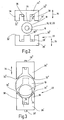
- the coil cores 26 ', 26 has an E-shaped configuration
- two can each inductively connected inductance coils 28 ', 28 "on the between the Central legs 36 and the outer legs 38 arranged connecting webs can be arranged, as shown in Fig. 4.
- To reduce the air gap losses are there additionally the middle leg 36 and the Outer leg 38 of different lengths. This will be the Polschenkel under reduction of the air gaps to the outer contour of the sleeve section 12 of the chuck 10 adapted.
- FIG. 4 the course of the magnetic field lines in Gleichpoligem operation represented the opposite magnetic poles.
- the sleeve section 12 of the chuck 10 consists of a magnetic and electrical conductive material, so that the field lines 40 in the shell region of the sleeve portion 12 are concentrated.
- the direction of the magnetic field is through the Arrows indicated on the field lines, with the direction of polarity the frequency of the alternating current applied to the induction coils 28 ', 28 " be reversed. Due to the skin effect arise only in Sheath area of the tube section eddy currents, which is the heat source for the Heating the sleeve section 12 form. The rest is by heat conduction heated from outside to inside.
- the induction coils 28', 28" are there each arranged on the connecting web 39.
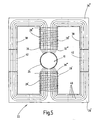
- the pole faces 30 ', 30 ", 32', 32" in adaptation to the Contour of the heated sleeve section 12 obliquely aligned. With that you can with one and the same coil assembly 22 different sized workpieces 10 are heated optimally.
- the temperature distribution over the To improve the circumference of the sleeve section 12 in that the coils 28 ', 28 "on the two coil cores 26 ', 26" in predetermined, possibly variable time intervals alternating with in-phase and out-of-phase AC currents are applied.
- the invention relates to a device for inductive heating of a preferably sleeve-shaped Workpiece part 12 of an existing electrically conductive material Workpiece 10 with a workpiece at least on its circumference partially comprehensive, acted upon by a high-frequency alternating current Coil arrangement 22nd order also complicated designed, with To heat thickened workpieces is, according to the Invention proposed a divisible coil assembly, the at least two each coil 28 ', 28 "carrying coil core 26', 26", whose Pole faces facing each other across an air gap, wherein the workpiece part 12 to be heated in the air gap 24 between the pole faces the coil core is insertable.
Landscapes
- Chemical & Material Sciences (AREA)
- Engineering & Computer Science (AREA)
- Mechanical Engineering (AREA)
- Physics & Mathematics (AREA)
- Thermal Sciences (AREA)
- Crystallography & Structural Chemistry (AREA)
- Materials Engineering (AREA)
- Metallurgy (AREA)
- Organic Chemistry (AREA)
- General Induction Heating (AREA)
- Heat Treatment Of Articles (AREA)
Description
- Fig. 1
- eine schaubildliche Darstellung einer induktiven Schrumpfstation für Werkzeuge mit geteilter Spulenanordnung welche nicht der Erfindung entspricht;
- Fig. 2
- eine Draufsicht auf die Spulenanordnung mit E-Kernen der Schrumpfanordnung nach Fig. 1;
- Fig. 3
- eine Draufsicht auf eine erfindungsgemäße Spulenanordnung mit U-Kernen und schrägen Polflächen;
- Fig. 4-6
- der Magnetfeldverlauf bei nicht der Erfindung entsprechenden entsprechenden Spulenarordnungen, wobei die einzelnen Figuren zeigen;
- Fig. 4
- ein Schema des Magnetfeldverlaufs in einer Spulenanordnung mit E-Kernen und gleichpoligen Polflächen;
- Fig. 5
- ein Schema des Magnetfeldverlaufs in einer Spulenanordnung mit E-Kernen und gegenpoligen Polflächen;
- Fig. 6
- ein Schema des Magnetfeldverlaufs in einer Spulenanordnung mit U-Kernen und gleichpoligen Polflächen.
Claims (12)
- Vorrichtung zum induktiven Aufheizen einer rotationssymmetrischen hülsenförmigen Werkstückpartie (12) eines aus elektrisch leitendem Material bestehenden Werkstücks (Spannfutter 10) mit einer die Werkstückpartie (12) an ihrem Umfang zumindest teilweise umfassenden mit einem hochfrequentem Wechselstrom beaufschlagbaren Spulenanordnung (22), wobei die Spulenanordnung (22) mindestens zwei durch einen in seiner Weite verstellbaren Luftspalt (24) getrennte, mindestens je eine Spule (28', 28") tragende Spulenkerne (26', 26") aus magnetisierbarem Material aufweist, deren Polflächen (30', 30 ", 30'''; 32', 32"; 32''') einander über den Luftspalt (24) hinweg zugewandt sind und deren Spulen (28', 28") unter Erzeugung eines an den einander jeweils zugewandten Polflächen gleichpoligen oder gegenpoligen Wechselmagnetfelds mit hochfrequentem Wechselstrom beaufschlagbar sind und wobei die aufzuheizende Werkstückpartie (12) in den Luftspalt (24) zwischen den Polflächen der Spulenkeme (26', 26") einführbar ist und die einander zugewandten Spulenkerne (26', 26") eine U-förmige Gestalt aufweisen, wobei die freien Polflächen (30', 30"; 32', 32") der U-Schenkel (38) der Spulenkerne (26', 26") unter Bildung des Luftspalts (24) einander zugewandt sind, dadurch gekennzeichnet, daß die freien Polflächen (30', 30"; 32', 32") und in Anpassung an die Außenkontur der aufzuheizenden Werkstückpartie (12) schräg ausgerichtet sind und dabei paarweise einen in Richtung Luftspalt (24) offenen Winkel miteinander einschließen.
- Vorrichtung nach Anspruch 1, dadurch gekennzeichnet, dass die auf den Spulenkernen (26', 26") angeordneten Spulen (28', 28") so mit Wechselstrom gleicher Frequenz und gleicher oder ungleicher Phase beaufschlagbar sind, dass die einander zugewandten Polflächen der Spulenkerne (26', 26") gleichpolig oder gegenpolig gepolt sind.
- Vorrichtung nach Anspruch 2, dadurch gekennzeichnet, dass die Spulen (28', 28") auf den beiden Spulenkernen (26', 26") in vorgegebenen Zeitabständen alternierend mit gleichphasigen und gegenphasigen Wechselströmen beaufschlagbar sind.
- Vorrichtung nach einem der Ansprüche 1 bis 3, dadurch gekennzeichnet, dass das Werkstück (10) zumindest im Bereich der aufzuheizenden Werkstückpartie (12) als hülsenförmige Werkzeugaufnahme ausgebildet ist.
- Vorrichtung nach einem der Ansprüche 1 bis 4, dadurch gekennzeichnet, dass das Werkstück (10) zumindest im Bereich der aufzuheizenden Werkstückpartie (12) aus einem weichmagnetischen Material, vorzugsweise aus einem Eisenwerkstoff besteht.
- Vorrichtung nach einem der Ansprüche 1 bis 5, dadurch gekennzeichnet, dass die einander zugewandten Schenkel (38) der Spulenkeme (26', 26") in ihrer Länge und in der Ausrichtung ihrer Polflächen an die Oberflächenkontur der aufzuheizenden Werkstückpartie (12) angepasst sind.
- Vorrichtung nach einem der Ansprüche 1 bis 6, dadurch gekennzeichnet, dass die Polflächen (30', 30"; 32', 32") der Spulenkerne (26', 26") zumindest teilweise mit einer Isolatorschicht überzogen sind.
- Vorrichtung nach Anspruch 7, dadurch gekennzeichnet, dass die Spulenkerne (26, 26') mit ihren Schenkeln (38) im Bereich der Isolatorschicht gegen die Oberfläche der aufzuheizenden Werkstückpartie (12) anschlagbar sind.
- Vorrichtung nach einem der Ansprüche 1 bis 8, dadurch gekennzeichnet, dass die Spulenkeme (26', 26") mit den zugehörigen Spulen (28', 28") unter Verkleinerung oder Vergrößerung des Luftspalts (24) begrenzt gegeneinander verschiebbar sind.
- Vorrichtung nach Anspruch 9, dadurch gekennzeichnet, dass die Spulenkerne (26', 26") entgegen der Kraft mindestens einer Feder relativ zueinander verschiebbar sind.
- Vorrichtung nach Anspruch 9 oder 10, dadurch gekennzeichnet, dass die Spulen (28, 28') auf den Spulenkernen (26', 26") mit einem Gleichstromanteil unter Aufbau eines die Spulenkerne (26', 26") entgegen der Kraft mindestens einer Feder voneinander abstoßenden oder einander anziehenden Kraft beaufschlagbar sind.
- Vorrichtung nach Anspruch 9, dadurch gekennzeichnet, dass die Spulenkerne (26', 26") motorisch gegeneinander verschiebbar sind.
Applications Claiming Priority (3)
| Application Number | Priority Date | Filing Date | Title |
|---|---|---|---|
| DE10046547A DE10046547A1 (de) | 2000-09-19 | 2000-09-19 | Vorrichtung zum induktiven Aufheizen von Werkstücken |
| DE10046547 | 2000-09-19 | ||
| PCT/EP2001/008446 WO2002024965A1 (de) | 2000-09-19 | 2001-07-21 | Vorrichtung zum induktiven aufheizen von werkstücken |
Publications (2)
| Publication Number | Publication Date |
|---|---|
| EP1325162A1 EP1325162A1 (de) | 2003-07-09 |
| EP1325162B1 true EP1325162B1 (de) | 2005-05-25 |
Family
ID=7656935
Family Applications (1)
| Application Number | Title | Priority Date | Filing Date |
|---|---|---|---|
| EP01969464A Expired - Lifetime EP1325162B1 (de) | 2000-09-19 | 2001-07-21 | Vorrichtung zum induktiven aufheizen von werkstücken |
Country Status (5)
| Country | Link |
|---|---|
| EP (1) | EP1325162B1 (de) |
| AT (1) | ATE296360T1 (de) |
| AU (1) | AU2001289717A1 (de) |
| DE (2) | DE10046547A1 (de) |
| WO (1) | WO2002024965A1 (de) |
Families Citing this family (11)
| Publication number | Priority date | Publication date | Assignee | Title |
|---|---|---|---|---|
| DE10255362B3 (de) * | 2002-11-27 | 2004-03-18 | Franz Haimer Maschinenbau Kg | Induktionsanordnung zum induktiven Erwärmen eines Werkzeughalters |
| DE102005005892A1 (de) | 2005-02-09 | 2006-08-10 | Haimer Gmbh | Induktionsspuleneinheit |
| DE102005021484A1 (de) * | 2005-05-10 | 2006-11-16 | Schaeffler Kg | Vorrichtung zur Erwärmung eines zylindrischen metallenen Werkstücks oder Werkstückabschnitts |
| DE102007051144B4 (de) * | 2007-07-26 | 2010-06-02 | Zenergy Power Gmbh | Induktionsheizer und Verfahren zum Verstellen der Breite der Schächte eines derartigen Induktionsheizers |
| EP2103689A1 (de) | 2008-03-19 | 2009-09-23 | Gentium S.p.A. | Synthetische Phosphodiester-Oligonukleotide und deren therapeutische Verwendungen |
| DE202009000804U1 (de) * | 2009-01-22 | 2010-03-11 | Elha-Maschinenbau Liemke Kg | Werkzeugmaschine |
| DE102011082613B4 (de) | 2011-09-13 | 2024-08-14 | Haimer Gmbh | Induktionsspuleneinheit |
| DE102011082611B4 (de) * | 2011-09-13 | 2024-10-10 | Franz Haimer Maschinenbau Kg | Induktionsspuleneinheit |
| WO2013112094A1 (en) * | 2012-01-26 | 2013-08-01 | Aktiebolaget Skf (Publ) | Induction hardening device |
| DE102017115202A1 (de) * | 2017-07-07 | 2019-01-10 | Bilz Werkzeugfabrik Gmbh & Co. Kg | Vorrichtung zum induktiven Erwärmen eines Bauteils |
| CN112247065A (zh) * | 2020-09-02 | 2021-01-22 | 欧阳建福 | 一种圆柱形工件均匀加热设备 |
Family Cites Families (5)
| Publication number | Priority date | Publication date | Assignee | Title |
|---|---|---|---|---|
| JPS531614A (en) * | 1976-06-26 | 1978-01-09 | Toyo Alum Kk | Induction heating equipment |
| DE2737730A1 (de) * | 1977-08-22 | 1979-03-08 | Schmalbach Lubeca | Verfahren und vorrichtung zum herstellen von nahtlosen dosenruempfen |
| JPS59116318A (ja) * | 1982-12-24 | 1984-07-05 | Mitsubishi Electric Corp | 誘導加熱装置 |
| WO1992009397A1 (en) * | 1990-11-30 | 1992-06-11 | Heron Technologies, Inc. | Induction dryer and magnetic separator |
| US6538239B1 (en) * | 1997-05-13 | 2003-03-25 | Walter James Anderson | Induction heating device for metal pieces |
-
2000
- 2000-09-19 DE DE10046547A patent/DE10046547A1/de not_active Withdrawn
-
2001
- 2001-07-21 WO PCT/EP2001/008446 patent/WO2002024965A1/de not_active Ceased
- 2001-07-21 AT AT01969464T patent/ATE296360T1/de not_active IP Right Cessation
- 2001-07-21 AU AU2001289717A patent/AU2001289717A1/en not_active Abandoned
- 2001-07-21 DE DE50106340T patent/DE50106340D1/de not_active Expired - Lifetime
- 2001-07-21 EP EP01969464A patent/EP1325162B1/de not_active Expired - Lifetime
Also Published As
| Publication number | Publication date |
|---|---|
| EP1325162A1 (de) | 2003-07-09 |
| ATE296360T1 (de) | 2005-06-15 |
| WO2002024965A1 (de) | 2002-03-28 |
| DE10046547A1 (de) | 2002-03-28 |
| DE50106340D1 (de) | 2005-06-30 |
| AU2001289717A1 (en) | 2002-04-02 |
Similar Documents
| Publication | Publication Date | Title |
|---|---|---|
| DE19915412B4 (de) | Vorrichtung zum Spannen von Werkzeugen | |
| EP1314511B1 (de) | Induktionsspule für ein induktives Schrumpfgerät | |
| EP1325162A1 (de) | Vorrichtung zum induktiven aufheizen von werkstücken | |
| DE69007508T2 (de) | Leistungssparender Magnetfeldgenerator hoher Wechselfeldstärke in Wehrschicht-Wirbelstrombauart. | |
| DE20203784U1 (de) | Vorrichtung zum induktiven Erwärmen eines Werkzeughalters | |
| DE2234472A1 (de) | Transformator mit relativ zueinander rotierenden koaxialen eisenkoerpern mit darin angeordneten ringspulen | |
| DE19532044A1 (de) | Induktionsheizwalze | |
| DE4343578A1 (de) | Vorrichtung zum induktiven Erwärmen elektrisch leitfähiger Werkstücke | |
| DE2609957C3 (de) | Verfahren zum Zusammenbauen von unmagnetischen, elektrischleitenden Bauteilen | |
| DE3873632T2 (de) | Induktionsheizgeraet. | |
| DE4214789C1 (en) | Transformer for high frequency applications - has annular ferrite core wound with pair of wire coils with core and components mounted on PCB | |
| DE2839114A1 (de) | Elektrische maschine, wie transformator, drosselspule, spannungskonstanthalter, o.dgl. | |
| DE202005012523U1 (de) | Vorrichtung zum induktiven Erwärmen von Werkzeugaufnahmen | |
| EP0761009B1 (de) | Verfahren und vorrichtung zum bewickeln eines geschlossenen ringkerns für transformatoren und drosseln hoher leistungen | |
| EP0283859B1 (de) | Spulenanordnung, Verfahren zur Herstellung von Spulenpaaren sowie Vorrichtung zur Herstellung von Spulenpaaren | |
| EP0977340B1 (de) | Rotor für eine dynamoelektrische Maschine | |
| DE1817496A1 (de) | Synchrogenerator mit zwei durch einen abgeschraegten Rotor gekoppelten stationaeren Wicklungen | |
| EP1772940A2 (de) | Rotierübertrager zur Übertragung von elektrischer Energie oder Information | |
| WO2005043567A1 (de) | Drehtransformator | |
| DE1003368B (de) | Zylinderfoermige oder andere prismatische Induktionsspule | |
| DE898223C (de) | Induktionsheizgeraet zum Waermebehandeln von metallischen Werkstuecken | |
| DE20023453U1 (de) | Vorrichtung zum Spannen von Werkzeugen | |
| DE3418173A1 (de) | Vorrichtung zum elektro-induktiven erhitzen von metallischen werkstuecken | |
| DE19847272B4 (de) | Verfahren zum Herstellen von Sintermetallkernen | |
| DE202007008704U1 (de) | Vorrichtung für das Ein- und Ausspannen von Werkzeugen |
Legal Events
| Date | Code | Title | Description |
|---|---|---|---|
| PUAI | Public reference made under article 153(3) epc to a published international application that has entered the european phase |
Free format text: ORIGINAL CODE: 0009012 |
|
| 17P | Request for examination filed |
Effective date: 20021115 |
|
| AK | Designated contracting states |
Designated state(s): AT BE CH CY DE DK ES FI FR GB GR IE IT LI LU MC NL PT SE TR |
|
| AX | Request for extension of the european patent |
Extension state: AL LT LV MK RO SI |
|
| GRAP | Despatch of communication of intention to grant a patent |
Free format text: ORIGINAL CODE: EPIDOSNIGR1 |
|
| GRAS | Grant fee paid |
Free format text: ORIGINAL CODE: EPIDOSNIGR3 |
|
| GRAA | (expected) grant |
Free format text: ORIGINAL CODE: 0009210 |
|
| AK | Designated contracting states |
Kind code of ref document: B1 Designated state(s): AT BE CH CY DE DK ES FI FR GB GR IE IT LI LU MC NL PT SE TR |
|
| PG25 | Lapsed in a contracting state [announced via postgrant information from national office to epo] |
Ref country code: IT Free format text: LAPSE BECAUSE OF FAILURE TO SUBMIT A TRANSLATION OF THE DESCRIPTION OR TO PAY THE FEE WITHIN THE PRESCRIBED TIME-LIMIT;WARNING: LAPSES OF ITALIAN PATENTS WITH EFFECTIVE DATE BEFORE 2007 MAY HAVE OCCURRED AT ANY TIME BEFORE 2007. THE CORRECT EFFECTIVE DATE MAY BE DIFFERENT FROM THE ONE RECORDED. Effective date: 20050525 Ref country code: IE Free format text: LAPSE BECAUSE OF FAILURE TO SUBMIT A TRANSLATION OF THE DESCRIPTION OR TO PAY THE FEE WITHIN THE PRESCRIBED TIME-LIMIT Effective date: 20050525 Ref country code: GB Free format text: LAPSE BECAUSE OF FAILURE TO SUBMIT A TRANSLATION OF THE DESCRIPTION OR TO PAY THE FEE WITHIN THE PRESCRIBED TIME-LIMIT Effective date: 20050525 Ref country code: NL Free format text: LAPSE BECAUSE OF FAILURE TO SUBMIT A TRANSLATION OF THE DESCRIPTION OR TO PAY THE FEE WITHIN THE PRESCRIBED TIME-LIMIT Effective date: 20050525 Ref country code: FI Free format text: LAPSE BECAUSE OF FAILURE TO SUBMIT A TRANSLATION OF THE DESCRIPTION OR TO PAY THE FEE WITHIN THE PRESCRIBED TIME-LIMIT Effective date: 20050525 Ref country code: TR Free format text: LAPSE BECAUSE OF FAILURE TO SUBMIT A TRANSLATION OF THE DESCRIPTION OR TO PAY THE FEE WITHIN THE PRESCRIBED TIME-LIMIT Effective date: 20050525 |
|
| REG | Reference to a national code |
Ref country code: GB Ref legal event code: FG4D Free format text: NOT ENGLISH |
|
| REG | Reference to a national code |
Ref country code: CH Ref legal event code: EP |
|
| REG | Reference to a national code |
Ref country code: IE Ref legal event code: FG4D Free format text: LANGUAGE OF EP DOCUMENT: GERMAN |
|
| REF | Corresponds to: |
Ref document number: 50106340 Country of ref document: DE Date of ref document: 20050630 Kind code of ref document: P |
|
| PG25 | Lapsed in a contracting state [announced via postgrant information from national office to epo] |
Ref country code: LU Free format text: LAPSE BECAUSE OF NON-PAYMENT OF DUE FEES Effective date: 20050721 Ref country code: CY Free format text: LAPSE BECAUSE OF FAILURE TO SUBMIT A TRANSLATION OF THE DESCRIPTION OR TO PAY THE FEE WITHIN THE PRESCRIBED TIME-LIMIT Effective date: 20050721 Ref country code: AT Free format text: LAPSE BECAUSE OF NON-PAYMENT OF DUE FEES Effective date: 20050721 |
|
| PG25 | Lapsed in a contracting state [announced via postgrant information from national office to epo] |
Ref country code: BE Free format text: LAPSE BECAUSE OF NON-PAYMENT OF DUE FEES Effective date: 20050731 Ref country code: CH Free format text: LAPSE BECAUSE OF NON-PAYMENT OF DUE FEES Effective date: 20050731 Ref country code: LI Free format text: LAPSE BECAUSE OF NON-PAYMENT OF DUE FEES Effective date: 20050731 Ref country code: MC Free format text: LAPSE BECAUSE OF NON-PAYMENT OF DUE FEES Effective date: 20050731 |
|
| PG25 | Lapsed in a contracting state [announced via postgrant information from national office to epo] |
Ref country code: SE Free format text: LAPSE BECAUSE OF FAILURE TO SUBMIT A TRANSLATION OF THE DESCRIPTION OR TO PAY THE FEE WITHIN THE PRESCRIBED TIME-LIMIT Effective date: 20050825 Ref country code: DK Free format text: LAPSE BECAUSE OF FAILURE TO SUBMIT A TRANSLATION OF THE DESCRIPTION OR TO PAY THE FEE WITHIN THE PRESCRIBED TIME-LIMIT Effective date: 20050825 Ref country code: GR Free format text: LAPSE BECAUSE OF FAILURE TO SUBMIT A TRANSLATION OF THE DESCRIPTION OR TO PAY THE FEE WITHIN THE PRESCRIBED TIME-LIMIT Effective date: 20050825 |
|
| PG25 | Lapsed in a contracting state [announced via postgrant information from national office to epo] |
Ref country code: ES Free format text: LAPSE BECAUSE OF FAILURE TO SUBMIT A TRANSLATION OF THE DESCRIPTION OR TO PAY THE FEE WITHIN THE PRESCRIBED TIME-LIMIT Effective date: 20050905 |
|
| PG25 | Lapsed in a contracting state [announced via postgrant information from national office to epo] |
Ref country code: PT Free format text: LAPSE BECAUSE OF FAILURE TO SUBMIT A TRANSLATION OF THE DESCRIPTION OR TO PAY THE FEE WITHIN THE PRESCRIBED TIME-LIMIT Effective date: 20051027 |
|
| NLV1 | Nl: lapsed or annulled due to failure to fulfill the requirements of art. 29p and 29m of the patents act | ||
| GBV | Gb: ep patent (uk) treated as always having been void in accordance with gb section 77(7)/1977 [no translation filed] |
Effective date: 20050525 |
|
| REG | Reference to a national code |
Ref country code: IE Ref legal event code: FD4D |
|
| REG | Reference to a national code |
Ref country code: CH Ref legal event code: PL |
|
| PLBE | No opposition filed within time limit |
Free format text: ORIGINAL CODE: 0009261 |
|
| STAA | Information on the status of an ep patent application or granted ep patent |
Free format text: STATUS: NO OPPOSITION FILED WITHIN TIME LIMIT |
|
| 26N | No opposition filed |
Effective date: 20060228 |
|
| EN | Fr: translation not filed | ||
| BERE | Be: lapsed |
Owner name: INNOVAT G.- FUR SONDERMASCHINENBAU, MESS- UND STEU Effective date: 20050731 Owner name: BILZ WERKZEUGFABRIK G.M.B.H. & CO. KG Effective date: 20050731 |
|
| PG25 | Lapsed in a contracting state [announced via postgrant information from national office to epo] |
Ref country code: FR Free format text: LAPSE BECAUSE OF NON-PAYMENT OF DUE FEES Effective date: 20050731 |
|
| PG25 | Lapsed in a contracting state [announced via postgrant information from national office to epo] |
Ref country code: FR Free format text: LAPSE BECAUSE OF NON-PAYMENT OF DUE FEES Effective date: 20050525 |
|
| PGFP | Annual fee paid to national office [announced via postgrant information from national office to epo] |
Ref country code: DE Payment date: 20170726 Year of fee payment: 17 |
|
| REG | Reference to a national code |
Ref country code: DE Ref legal event code: R119 Ref document number: 50106340 Country of ref document: DE |
|
| PG25 | Lapsed in a contracting state [announced via postgrant information from national office to epo] |
Ref country code: DE Free format text: LAPSE BECAUSE OF NON-PAYMENT OF DUE FEES Effective date: 20190201 |