EP1324569B1 - Aufklappbares elektronisches Gerät - Google Patents
Aufklappbares elektronisches Gerät Download PDFInfo
- Publication number
- EP1324569B1 EP1324569B1 EP01310922A EP01310922A EP1324569B1 EP 1324569 B1 EP1324569 B1 EP 1324569B1 EP 01310922 A EP01310922 A EP 01310922A EP 01310922 A EP01310922 A EP 01310922A EP 1324569 B1 EP1324569 B1 EP 1324569B1
- Authority
- EP
- European Patent Office
- Prior art keywords
- edge
- adjacent
- open configuration
- operating controls
- open
- Prior art date
- Legal status (The legal status is an assumption and is not a legal conclusion. Google has not performed a legal analysis and makes no representation as to the accuracy of the status listed.)
- Expired - Lifetime
Links
Images


Classifications
-
- G—PHYSICS
- G06—COMPUTING OR CALCULATING; COUNTING
- G06F—ELECTRIC DIGITAL DATA PROCESSING
- G06F1/00—Details not covered by groups G06F3/00 - G06F13/00 and G06F21/00
- G06F1/16—Constructional details or arrangements
- G06F1/1613—Constructional details or arrangements for portable computers
- G06F1/1633—Constructional details or arrangements of portable computers not specific to the type of enclosures covered by groups G06F1/1615 - G06F1/1626
- G06F1/1675—Miscellaneous details related to the relative movement between the different enclosures or enclosure parts
- G06F1/1677—Miscellaneous details related to the relative movement between the different enclosures or enclosure parts for detecting open or closed state or particular intermediate positions assumed by movable parts of the enclosure, e.g. detection of display lid position with respect to main body in a laptop, detection of opening of the cover of battery compartment
-
- G—PHYSICS
- G06—COMPUTING OR CALCULATING; COUNTING
- G06F—ELECTRIC DIGITAL DATA PROCESSING
- G06F1/00—Details not covered by groups G06F3/00 - G06F13/00 and G06F21/00
- G06F1/16—Constructional details or arrangements
- G06F1/1613—Constructional details or arrangements for portable computers
- G06F1/1615—Constructional details or arrangements for portable computers with several enclosures having relative motions, each enclosure supporting at least one I/O or computing function
- G06F1/1616—Constructional details or arrangements for portable computers with several enclosures having relative motions, each enclosure supporting at least one I/O or computing function with folding flat displays, e.g. laptop computers or notebooks having a clamshell configuration, with body parts pivoting to an open position around an axis parallel to the plane they define in closed position
-
- G—PHYSICS
- G06—COMPUTING OR CALCULATING; COUNTING
- G06F—ELECTRIC DIGITAL DATA PROCESSING
- G06F1/00—Details not covered by groups G06F3/00 - G06F13/00 and G06F21/00
- G06F1/16—Constructional details or arrangements
- G06F1/1613—Constructional details or arrangements for portable computers
- G06F1/1633—Constructional details or arrangements of portable computers not specific to the type of enclosures covered by groups G06F1/1615 - G06F1/1626
- G06F1/1662—Details related to the integrated keyboard
- G06F1/1671—Special purpose buttons or auxiliary keyboards, e.g. retractable mini keypads, keypads or buttons that remain accessible at closed laptop
-
- H—ELECTRICITY
- H04—ELECTRIC COMMUNICATION TECHNIQUE
- H04M—TELEPHONIC COMMUNICATION
- H04M1/00—Substation equipment, e.g. for use by subscribers
- H04M1/02—Constructional features of telephone sets
- H04M1/0202—Portable telephone sets, e.g. cordless phones, mobile phones or bar type handsets
- H04M1/0206—Portable telephones comprising a plurality of mechanically joined movable body parts, e.g. hinged housings
- H04M1/0208—Portable telephones comprising a plurality of mechanically joined movable body parts, e.g. hinged housings characterized by the relative motions of the body parts
- H04M1/0214—Foldable telephones, i.e. with body parts pivoting to an open position around an axis parallel to the plane they define in closed position
- H04M1/0216—Foldable in one direction, i.e. using a one degree of freedom hinge
-
- E—FIXED CONSTRUCTIONS
- E05—LOCKS; KEYS; WINDOW OR DOOR FITTINGS; SAFES
- E05D—HINGES OR SUSPENSION DEVICES FOR DOORS, WINDOWS OR WINGS
- E05D15/00—Suspension arrangements for wings
- E05D15/48—Suspension arrangements for wings allowing alternative movements
- E05D15/50—Suspension arrangements for wings allowing alternative movements for opening at either of two opposite edges
- E05D15/507—Suspension arrangements for wings allowing alternative movements for opening at either of two opposite edges by detachment of the hinge from the wing or the frame
-
- E—FIXED CONSTRUCTIONS
- E05—LOCKS; KEYS; WINDOW OR DOOR FITTINGS; SAFES
- E05Y—INDEXING SCHEME ASSOCIATED WITH SUBCLASSES E05D AND E05F, RELATING TO CONSTRUCTION ELEMENTS, ELECTRIC CONTROL, POWER SUPPLY, POWER SIGNAL OR TRANSMISSION, USER INTERFACES, MOUNTING OR COUPLING, DETAILS, ACCESSORIES, AUXILIARY OPERATIONS NOT OTHERWISE PROVIDED FOR, APPLICATION THEREOF
- E05Y2201/00—Constructional elements; Accessories therefor
- E05Y2201/60—Suspension or transmission members; Accessories therefor
- E05Y2201/622—Suspension or transmission members elements
- E05Y2201/624—Arms
-
- E—FIXED CONSTRUCTIONS
- E05—LOCKS; KEYS; WINDOW OR DOOR FITTINGS; SAFES
- E05Y—INDEXING SCHEME ASSOCIATED WITH SUBCLASSES E05D AND E05F, RELATING TO CONSTRUCTION ELEMENTS, ELECTRIC CONTROL, POWER SUPPLY, POWER SIGNAL OR TRANSMISSION, USER INTERFACES, MOUNTING OR COUPLING, DETAILS, ACCESSORIES, AUXILIARY OPERATIONS NOT OTHERWISE PROVIDED FOR, APPLICATION THEREOF
- E05Y2999/00—Subject-matter not otherwise provided for in this subclass
Definitions
- the present invention relates to electronic devices, and, more particularly, to electronic devices that can physically be manipulated between different configurations.
- the invention has been developed primarily for use in the fields of personal digital assistants and mobile telephone handsets, and will be described hereinafter with reference to these applications. However, it will be appreciated that the invention has application in a number of alternative electronic devices.
- US Patent No. 5,494,447 which relates to a hinge assembly for electronic devices that allows for lineal and rotational adjustment of each device part.
- European Patent Application Publication No. 0807879 relates to an information processing apparatus having a main body and a lid body configured so that the lid body may be configured between a closed state, a stacked state, a double screen state and an inverted state.
- a device foldable between a first open configuration, a closed configuration and a second open configuration including:a first body portion having a first edge, a first face and a second edge opposite the first edge; a second body portion having a third edge, a second face and a fourth edge opposite the third edge; a first connecting member, one end of which is hingedly connected to the first edge and an opposite end of which is hingedly connected to the third edge; and a second member, one end of which is hingedly connected to the second edge and an opposite end of which is hingedly connected to the fourth edge; the apparatus being configured such that: in the closed configuration the first edge is adjacent the fourth edge and the second edge is adjacent the third edge; in the first open configuration the second edge is adjacent the third edge and the first edge is not adjacent the fourth edge; and in the second open configuration the first edge is adjacent the fourth edge and the second edge is not adjacent the third edge; characterized in that the device is an electronic apparatus, and in that in the first open configuration a first set
- At least some of the operating controls are on at least one of the members, such that they are accessible on that member only in one of the two open configurations.
- both sides of at least one of the members includes one or more of the operating controls, such that that member reveals the operating controls on one of its sides when in the first open configuration and on the other of its sides when in the second open configuration.
- one or more of members has a through hole or other through contour that surrounds or lies adjacent one or more of the operating controls when in one of the open configurations, such that indicia on the member adjacent the hole or shape labels that operating control when in that open configuration.
- the hole or contour surrounds one or more of the operating controls in the first open configurations, and one or more other operating controls in the second open configuration, such that indicia adjacent the hole or shape label the operating controls when adjacent the operating controls in each of the respective open configurations.
- FIG. 1 there is shown an electronic apparatus 100 foldable between a first open configuration, a closed configuration and a second open configuration. It will be appreciated that the apparatus has not been drawn to scale and has somewhat looser connections than would be the case in an engineered version, to enable a better understanding of the multi-way hinge connection.
- the apparatus 100 includes a first body portion 102 having a first edge 104, a first face 106 and a second edge 108 substantially opposite the first edge.
- a second body portion 110 has a third edge 112, a second face 114 and a fourth edge 116 substantially opposite the third edge.
- a first connecting member 118 has one end 120 hingedly connected to the first edge 104 by a first hinge 105 and an opposite end 122 hingedly connected to the third edge 112 by a third hinge 113.
- a second member 123 has one end 124 hingedly connected to the second edge 108 by a second hinge 109 and an opposite end 126 which is hingedly connected to the fourth edge 116 by a fourth hinge 117.
- a first set of operating controls 128 are disposed on the first face 106 and a second set of operating controls 130 are disposed on the second face 114.
- the first set 128 includes operating buttons 132 and the second set 130 includes buttons 134.
- the first face 106 also includes an operating display 136.
- the apparatus of figure 1 In a closed position (not shown) the apparatus of figure 1 has the first edge adjacent the fourth edge and the second edge adjacent the third edge.
- the operating controls and the display are then enclosed and protected by the first body portion 102 and the second body portion 110.
- the display When the device is opened into a first open configuration, as shown in Figure 1, the display is uncovered, as are the first and second sets of controls.
- the user can then implement any combination of data required.
- data can be input via either or both sets of buttons. It will be appreciated that a greater number of operating control buttons will be desirable in such an embodiment, but for the purposes of simplicity, only a small number of such buttons are shown.
- the fourth and first edges are first swung back together around the axes of the second and third hinges.
- the second and third edges are then separated from each other and the apparatus rotated into the second open position about the axes of the first and fourth hinges.
- the first and fourth hinge axes will be substantially coincident, as will those of the second and third hinge axes, to ensure that the device closes completely between the two open configurations.
- the members are too long for this to occur, for the sake of understanding the mechanics of the invention.
- the first member covers the second set of operating controls, such that a user cannot see or access them. Also, the operating display is obscured by the position of the second member.
- the different side of the members, and the areas that they obscure in different open configurations, can be coloured differently, and can include indicia that is revealed or obscured depending upon which of the two open configurations are in use. This provides the ability for a visual appearance that is customisable depending upon the configuration.
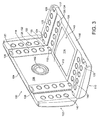
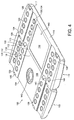
- FIG. 2 to 5 An alternative embodiment is shown in Figures 2 to 5, which shows a design that is correctly engineered such that the apparatus closed properly intermediate the first and second open configurations.
- the main distinction is that there are third 136 and fourth 138 members that operate similar to the respective first and second members. This enables a more stable apparatus that is more resistant to undesirable torsional forces in use, as well as providing more options for changing the appearance of the operating controls in the two open configurations.
- buttons 140 themselves include operating controls in the form of buttons 140. Whilst such buttons are shown on all sides of the members, it will be appreciated that this is optional, and that such buttons or other operating controls can appear on either or both sides of one or more of the members (or not at all, as in the Figure 1 embodiment).
- the apparatus in this embodiment is a handset for two-way video telephony, and therefore includes a camera 142 and a display 143 for displaying video from another device to which the displayed apparatus is connected via, for example, a wireless network.
- Figure 2 shows the apparatus in the closed configuration.
- Figure 3 shows the apparatus partially opening into the first open configuration.
- Figure 4 shows the device completely in the first open configuration.
- Figure 5 shows the apparatus completely in the second open configuration. It will be noted that alternative controls are now visible on each of the members, whilst the controls that were visible in Figures 3 and 4 are hidden. Similarly, the members have obscured some controls on the first and second faces that were visible in the first open configuration, and revealed some others that they obscured in the first configuration. In a preferred form, the controls are visually brighter in Figures 3 and 4, due to the colours chosen for the sides of the members that are shown in those Figures. Figure 5 reveals a more sombre colour scheme. The sparkling version could be, for example, a game, whilst the more sombre version could implement the more conservative video telephony configuration.
- positions of the members in the two configurations can also reveal or obscure indicia, such as numbers, letters or diagrams, that can modify the way a user understands an operating control.
- a member can have a first function label on one side (visible in the first open configuration) and a second function label on the other side. These labels are disposed adjacent an operating control to which they relate, when the apparatus is in the configuration that allows that function to be implemented by activating that operating control.
- the apparatus in one orientation can be configured to act as a mobile communication handset, whilst in another it can operate as a PDA.
- one configuration can be a language translator and the other a calculator. It will be understood that although the preferred embodiment incorporates a telecommunications handset in at least one embodiment, any combination of devices or operating configurations can be implemented.
Landscapes
- Engineering & Computer Science (AREA)
- Computer Hardware Design (AREA)
- Theoretical Computer Science (AREA)
- Physics & Mathematics (AREA)
- General Engineering & Computer Science (AREA)
- General Physics & Mathematics (AREA)
- Human Computer Interaction (AREA)
- Signal Processing (AREA)
- Mathematical Physics (AREA)
- Telephone Set Structure (AREA)
- Pivots And Pivotal Connections (AREA)
- Casings For Electric Apparatus (AREA)
- Closing And Opening Devices For Wings, And Checks For Wings (AREA)
- Fittings On The Vehicle Exterior For Carrying Loads, And Devices For Holding Or Mounting Articles (AREA)
- Telephone Function (AREA)
Claims (5)
- Vorrichtung (100), die faltbar zwischen einer ersten offenen Konfiguration, einer geschlossenen Konfiguration und einer zweiten offenen Konfiguration ist, wobei das Gerät einschließt:- einen ersten Körperabschnitt (102), der einen ersten Rand (104), eine erste Fläche (106) und einen zweiten Rand (108) gegenüber des ersten Rands aufweist;- einen zweiten Körperabschnitt (110), der einen dritten Rand (112), eine zweite Fläche (114) und einen vierten Rand (116) gegenüber des dritten Rands aufweist;- ein erstes Verbindungselement (118), wobei ein Ende davon gelenkig mit dem erste Rand verbunden ist und ein gegenüberliegendes Ende davon gelenkig mit dem dritten Rand verbunden ist; und- ein zweites Verbindungselement (123), wobei ein Ende davon gelenkig mit dem zweiten Rand verbunden ist und ein gegenüberliegendes Ende davon gelenkig mit dem vierten Rand verbunden ist;wobei das Gerät derart konfiguriert ist, dass:- der erste Rand in der geschlossenen Konfiguration an den vierten Rand angrenzt und der zweite Rand an den dritten Rand angrenzt.- der zweite Rand in der ersten offenen Konfiguration an den dritten Rand angrenzt und der erste Rand nicht an den vierten Rand angrenzt;- der erste Rand in der zweiten offenen Konfiguration an den vierten Rand angrenzt und der zweite Rand nicht an den dritten Rand angrenzt;dadurch gekennzeichnet, dass die Vorrichtung ein elektrisches Gerät ist und dass in der ersten offenen Konfiguration ein erster Satz von Bedienelementen (128) offen gelegt ist, und in der zweiten offenen Konfiguration ein zweiter Satz von Bedienelementen (130) offen gelegt ist, und das Aussehen oder die Bedienung des ersten und zweiten Satzes von Bedienelementen verändert wird, indem einer der beiden oder beide Verbindungselemente die Bedienelemente in der ersten bzw. zweiten offenen Konfiguration verdecken oder offenlegen.
- Vorrichtung nach Anspruch 1, wobei sich mindestens einige der Bedienelemente auf mindestens einem der Elemente befinden, so dass sie auf dem Element nur in einer der beiden offenen Konfigurationen zugänglich sind.
- Vorrichtung nach Anspruch 2, wobei beide Seiten des mindestens einen der Elemente einen oder mehrere der Bedienelemente einschließen, so dass dieses Element die Bedienelemente auf einer seiner Seiten offenlegt, wenn es sich in der ersten offenen Konfiguration befindet und auf der anderen seiner Seite offenlegt, wenn es sich in der zweiten offenen Konfiguration befindet.
- Vorrichtung nach Anspruch 1 oder 2, wobei ein oder mehrere der Elemente ein Durchgangsloch oder eine andere durchgehende Kontur aufweisen, die in einer der offenen Konfigurationen ein oder mehrere der Bedienelemente umgibt oder an ein oder mehrere der Bedienelemente angrenzend liegt, so dass in dieser geöffneten Konfiguration Zeichen auf dem Element, die an das Loch angrenzen oder die Form, das Bedienelement kennzeichnen.
- Vorrichtung nach Anspruch 4, wobei das Loch oder die Kontur in der ersten offenen Konfiguration ein oder mehrere der Bedienelemente und in der zweiten offenen Konfiguration ein oder mehrere andere der Bedienelemente umgeben, so dass Zeichen, die an das Loch angrenzen oder Form, die Bedienelemente kennzeichnen, wenn sie in jeder der jeweiligen geöffneten Konfigurationen an die Bedienelemente angrenzen.
Priority Applications (3)
| Application Number | Priority Date | Filing Date | Title |
|---|---|---|---|
| EP01310922A EP1324569B1 (de) | 2001-12-28 | 2001-12-28 | Aufklappbares elektronisches Gerät |
| AT01310922T ATE335351T1 (de) | 2001-12-28 | 2001-12-28 | Aufklappbares elektronisches gerät |
| DE60121975T DE60121975T2 (de) | 2001-12-28 | 2001-12-28 | Aufklappbares elektronisches Gerät |
Applications Claiming Priority (1)
| Application Number | Priority Date | Filing Date | Title |
|---|---|---|---|
| EP01310922A EP1324569B1 (de) | 2001-12-28 | 2001-12-28 | Aufklappbares elektronisches Gerät |
Publications (2)
| Publication Number | Publication Date |
|---|---|
| EP1324569A1 EP1324569A1 (de) | 2003-07-02 |
| EP1324569B1 true EP1324569B1 (de) | 2006-08-02 |
Family
ID=8182581
Family Applications (1)
| Application Number | Title | Priority Date | Filing Date |
|---|---|---|---|
| EP01310922A Expired - Lifetime EP1324569B1 (de) | 2001-12-28 | 2001-12-28 | Aufklappbares elektronisches Gerät |
Country Status (3)
| Country | Link |
|---|---|
| EP (1) | EP1324569B1 (de) |
| AT (1) | ATE335351T1 (de) |
| DE (1) | DE60121975T2 (de) |
Family Cites Families (6)
| Publication number | Priority date | Publication date | Assignee | Title |
|---|---|---|---|---|
| US4132034A (en) * | 1977-10-25 | 1979-01-02 | Siclen William C Van | Refrigerator door with double acting hinge |
| FR2562599A1 (fr) * | 1984-04-06 | 1985-10-11 | Bride Marcel | Dispositif d'ouverture bilaterale de portes, vantaux ou couvercles de tous meubles ou objets necessitant un acces par deux cotes opposes |
| US5103376A (en) * | 1991-02-19 | 1992-04-07 | At&T Bell Laboratories | Dual position computer arrangement |
| WO1994023476A1 (en) * | 1993-03-26 | 1994-10-13 | Zaidan Khalil S | Hinge assembly for electronic devices |
| DE4416370A1 (de) * | 1993-08-03 | 1995-02-09 | Dux Juergen Dipl Designer | Klappkarte |
| JP3222764B2 (ja) * | 1996-05-17 | 2001-10-29 | シャープ株式会社 | 情報処理装置 |
-
2001
- 2001-12-28 EP EP01310922A patent/EP1324569B1/de not_active Expired - Lifetime
- 2001-12-28 DE DE60121975T patent/DE60121975T2/de not_active Expired - Lifetime
- 2001-12-28 AT AT01310922T patent/ATE335351T1/de not_active IP Right Cessation
Also Published As
| Publication number | Publication date |
|---|---|
| DE60121975D1 (de) | 2006-09-14 |
| DE60121975T2 (de) | 2007-03-01 |
| EP1324569A1 (de) | 2003-07-02 |
| ATE335351T1 (de) | 2006-08-15 |
Similar Documents
| Publication | Publication Date | Title |
|---|---|---|
| US7991442B2 (en) | Multiple opening and closing type mobile communication terminal | |
| EP1186111B1 (de) | Kombinierter persöhnliger hilfsrechner/telefon | |
| EP1161062B1 (de) | Klappbares elektronisches Gerät | |
| US7158817B2 (en) | Portable terminal | |
| US7184796B2 (en) | Personal communication device having a built in projection display | |
| US20010003707A1 (en) | Portable radio apparatus with additional display unit | |
| KR20020087847A (ko) | 이동 통신 장치용 폴더형 키보드 | |
| KR20050049976A (ko) | 슬라이딩/회전성 힌지 수단을 구비한 휴대용 디지털 통신장치 | |
| US7450968B2 (en) | Mobile communication device with slide portion | |
| KR100993095B1 (ko) | 폴더식 휴대기기 | |
| WO2006071414A1 (en) | Hinged electronic device with hinged screen | |
| EP1710986B1 (de) | Faltbares und tragbares Kommunikationsgerät mit verschiebbarer Anzeige | |
| CN1612487A (zh) | 移动终端和滑动模块及其方法 | |
| US7443979B2 (en) | Portable communication terminal having a housing capable of both sliding and swinging | |
| KR20060039750A (ko) | 임의의 각도로 슬라이드 개폐되는 커버부를 갖는슬라이드형 이동통신 단말기 | |
| EP1324569B1 (de) | Aufklappbares elektronisches Gerät | |
| US20050134568A1 (en) | Method and system for providing a rotated keyboard and angled display in a hand-held computing device | |
| KR101328053B1 (ko) | 이동통신 단말기 | |
| US20090117952A1 (en) | Mobile phone | |
| US20030155216A1 (en) | Keypad assembly for portable radio terminal | |
| JP2001358811A (ja) | 携帯型情報端末装置 | |
| KR100592182B1 (ko) | 360도 회전하는 폴더형 이동통신 단말기 | |
| KR100628744B1 (ko) | 이동통신단말기의 슬라이더 개폐장치 | |
| KR100396522B1 (ko) | 폴더형 통신 장치 | |
| KR20040060566A (ko) | 화면크기가 가변되는 휴대용 단말기 |
Legal Events
| Date | Code | Title | Description |
|---|---|---|---|
| PUAI | Public reference made under article 153(3) epc to a published international application that has entered the european phase |
Free format text: ORIGINAL CODE: 0009012 |
|
| AK | Designated contracting states |
Designated state(s): AT BE CH CY DE DK ES FI FR GB GR IE IT LI LU MC NL PT SE TR |
|
| AX | Request for extension of the european patent |
Extension state: AL LT LV MK RO SI |
|
| 17P | Request for examination filed |
Effective date: 20031230 |
|
| AKX | Designation fees paid |
Designated state(s): AT BE CH CY DE DK ES FI FR GB GR IE IT LI LU MC NL PT SE TR |
|
| GRAP | Despatch of communication of intention to grant a patent |
Free format text: ORIGINAL CODE: EPIDOSNIGR1 |
|
| GRAS | Grant fee paid |
Free format text: ORIGINAL CODE: EPIDOSNIGR3 |
|
| GRAA | (expected) grant |
Free format text: ORIGINAL CODE: 0009210 |
|
| AK | Designated contracting states |
Kind code of ref document: B1 Designated state(s): AT BE CH CY DE DK ES FI FR GB GR IE IT LI LU MC NL PT SE TR |
|
| PG25 | Lapsed in a contracting state [announced via postgrant information from national office to epo] |
Ref country code: IT Free format text: LAPSE BECAUSE OF FAILURE TO SUBMIT A TRANSLATION OF THE DESCRIPTION OR TO PAY THE FEE WITHIN THE PRESCRIBED TIME-LIMIT;WARNING: LAPSES OF ITALIAN PATENTS WITH EFFECTIVE DATE BEFORE 2007 MAY HAVE OCCURRED AT ANY TIME BEFORE 2007. THE CORRECT EFFECTIVE DATE MAY BE DIFFERENT FROM THE ONE RECORDED. Effective date: 20060802 Ref country code: NL Free format text: LAPSE BECAUSE OF FAILURE TO SUBMIT A TRANSLATION OF THE DESCRIPTION OR TO PAY THE FEE WITHIN THE PRESCRIBED TIME-LIMIT Effective date: 20060802 Ref country code: LI Free format text: LAPSE BECAUSE OF FAILURE TO SUBMIT A TRANSLATION OF THE DESCRIPTION OR TO PAY THE FEE WITHIN THE PRESCRIBED TIME-LIMIT Effective date: 20060802 Ref country code: CH Free format text: LAPSE BECAUSE OF FAILURE TO SUBMIT A TRANSLATION OF THE DESCRIPTION OR TO PAY THE FEE WITHIN THE PRESCRIBED TIME-LIMIT Effective date: 20060802 Ref country code: FI Free format text: LAPSE BECAUSE OF FAILURE TO SUBMIT A TRANSLATION OF THE DESCRIPTION OR TO PAY THE FEE WITHIN THE PRESCRIBED TIME-LIMIT Effective date: 20060802 Ref country code: BE Free format text: LAPSE BECAUSE OF FAILURE TO SUBMIT A TRANSLATION OF THE DESCRIPTION OR TO PAY THE FEE WITHIN THE PRESCRIBED TIME-LIMIT Effective date: 20060802 Ref country code: AT Free format text: LAPSE BECAUSE OF FAILURE TO SUBMIT A TRANSLATION OF THE DESCRIPTION OR TO PAY THE FEE WITHIN THE PRESCRIBED TIME-LIMIT Effective date: 20060802 |
|
| REG | Reference to a national code |
Ref country code: GB Ref legal event code: FG4D |
|
| REG | Reference to a national code |
Ref country code: CH Ref legal event code: EP |
|
| REG | Reference to a national code |
Ref country code: IE Ref legal event code: FG4D |
|
| REF | Corresponds to: |
Ref document number: 60121975 Country of ref document: DE Date of ref document: 20060914 Kind code of ref document: P |
|
| PG25 | Lapsed in a contracting state [announced via postgrant information from national office to epo] |
Ref country code: SE Free format text: LAPSE BECAUSE OF FAILURE TO SUBMIT A TRANSLATION OF THE DESCRIPTION OR TO PAY THE FEE WITHIN THE PRESCRIBED TIME-LIMIT Effective date: 20061102 Ref country code: DK Free format text: LAPSE BECAUSE OF FAILURE TO SUBMIT A TRANSLATION OF THE DESCRIPTION OR TO PAY THE FEE WITHIN THE PRESCRIBED TIME-LIMIT Effective date: 20061102 |
|
| PG25 | Lapsed in a contracting state [announced via postgrant information from national office to epo] |
Ref country code: ES Free format text: LAPSE BECAUSE OF FAILURE TO SUBMIT A TRANSLATION OF THE DESCRIPTION OR TO PAY THE FEE WITHIN THE PRESCRIBED TIME-LIMIT Effective date: 20061113 |
|
| PG25 | Lapsed in a contracting state [announced via postgrant information from national office to epo] |
Ref country code: IE Free format text: LAPSE BECAUSE OF NON-PAYMENT OF DUE FEES Effective date: 20061228 |
|
| PG25 | Lapsed in a contracting state [announced via postgrant information from national office to epo] |
Ref country code: MC Free format text: LAPSE BECAUSE OF NON-PAYMENT OF DUE FEES Effective date: 20061231 |
|
| NLV1 | Nl: lapsed or annulled due to failure to fulfill the requirements of art. 29p and 29m of the patents act | ||
| PG25 | Lapsed in a contracting state [announced via postgrant information from national office to epo] |
Ref country code: PT Free format text: LAPSE BECAUSE OF FAILURE TO SUBMIT A TRANSLATION OF THE DESCRIPTION OR TO PAY THE FEE WITHIN THE PRESCRIBED TIME-LIMIT Effective date: 20070102 |
|
| ET | Fr: translation filed | ||
| REG | Reference to a national code |
Ref country code: CH Ref legal event code: PL |
|
| PLBE | No opposition filed within time limit |
Free format text: ORIGINAL CODE: 0009261 |
|
| STAA | Information on the status of an ep patent application or granted ep patent |
Free format text: STATUS: NO OPPOSITION FILED WITHIN TIME LIMIT |
|
| 26N | No opposition filed |
Effective date: 20070503 |
|
| PG25 | Lapsed in a contracting state [announced via postgrant information from national office to epo] |
Ref country code: GR Free format text: LAPSE BECAUSE OF FAILURE TO SUBMIT A TRANSLATION OF THE DESCRIPTION OR TO PAY THE FEE WITHIN THE PRESCRIBED TIME-LIMIT Effective date: 20061103 |
|
| PG25 | Lapsed in a contracting state [announced via postgrant information from national office to epo] |
Ref country code: LU Free format text: LAPSE BECAUSE OF NON-PAYMENT OF DUE FEES Effective date: 20061228 Ref country code: TR Free format text: LAPSE BECAUSE OF FAILURE TO SUBMIT A TRANSLATION OF THE DESCRIPTION OR TO PAY THE FEE WITHIN THE PRESCRIBED TIME-LIMIT Effective date: 20060802 |
|
| PG25 | Lapsed in a contracting state [announced via postgrant information from national office to epo] |
Ref country code: CY Free format text: LAPSE BECAUSE OF FAILURE TO SUBMIT A TRANSLATION OF THE DESCRIPTION OR TO PAY THE FEE WITHIN THE PRESCRIBED TIME-LIMIT Effective date: 20060802 |
|
| PGFP | Annual fee paid to national office [announced via postgrant information from national office to epo] |
Ref country code: FR Payment date: 20091221 Year of fee payment: 9 Ref country code: GB Payment date: 20091223 Year of fee payment: 9 |
|
| PGFP | Annual fee paid to national office [announced via postgrant information from national office to epo] |
Ref country code: DE Payment date: 20091224 Year of fee payment: 9 |
|
| GBPC | Gb: european patent ceased through non-payment of renewal fee |
Effective date: 20101228 |
|
| REG | Reference to a national code |
Ref country code: FR Ref legal event code: ST Effective date: 20110831 |
|
| PG25 | Lapsed in a contracting state [announced via postgrant information from national office to epo] |
Ref country code: FR Free format text: LAPSE BECAUSE OF NON-PAYMENT OF DUE FEES Effective date: 20110103 |
|
| PG25 | Lapsed in a contracting state [announced via postgrant information from national office to epo] |
Ref country code: GB Free format text: LAPSE BECAUSE OF NON-PAYMENT OF DUE FEES Effective date: 20101228 Ref country code: DE Free format text: LAPSE BECAUSE OF NON-PAYMENT OF DUE FEES Effective date: 20110701 |
|
| REG | Reference to a national code |
Ref country code: DE Ref legal event code: R119 Ref document number: 60121975 Country of ref document: DE Effective date: 20110701 |