EP1324465A2 - An electric motor - Google Patents
An electric motor Download PDFInfo
- Publication number
- EP1324465A2 EP1324465A2 EP02258614A EP02258614A EP1324465A2 EP 1324465 A2 EP1324465 A2 EP 1324465A2 EP 02258614 A EP02258614 A EP 02258614A EP 02258614 A EP02258614 A EP 02258614A EP 1324465 A2 EP1324465 A2 EP 1324465A2
- Authority
- EP
- European Patent Office
- Prior art keywords
- motor
- rotor
- stator
- sensors
- pump
- Prior art date
- Legal status (The legal status is an assumption and is not a legal conclusion. Google has not performed a legal analysis and makes no representation as to the accuracy of the status listed.)
- Granted
Links
Images


Classifications
-
- F—MECHANICAL ENGINEERING; LIGHTING; HEATING; WEAPONS; BLASTING
- F02—COMBUSTION ENGINES; HOT-GAS OR COMBUSTION-PRODUCT ENGINE PLANTS
- F02M—SUPPLYING COMBUSTION ENGINES IN GENERAL WITH COMBUSTIBLE MIXTURES OR CONSTITUENTS THEREOF
- F02M37/00—Apparatus or systems for feeding liquid fuel from storage containers to carburettors or fuel-injection apparatus; Arrangements for purifying liquid fuel specially adapted for, or arranged on, internal-combustion engines
- F02M37/04—Feeding by means of driven pumps
- F02M37/08—Feeding by means of driven pumps electrically driven
-
- H—ELECTRICITY
- H02—GENERATION; CONVERSION OR DISTRIBUTION OF ELECTRIC POWER
- H02K—DYNAMO-ELECTRIC MACHINES
- H02K1/00—Details of the magnetic circuit
- H02K1/06—Details of the magnetic circuit characterised by the shape, form or construction
- H02K1/12—Stationary parts of the magnetic circuit
- H02K1/14—Stator cores with salient poles
- H02K1/146—Stator cores with salient poles consisting of a generally annular yoke with salient poles
- H02K1/148—Sectional cores
-
- H—ELECTRICITY
- H02—GENERATION; CONVERSION OR DISTRIBUTION OF ELECTRIC POWER
- H02K—DYNAMO-ELECTRIC MACHINES
- H02K1/00—Details of the magnetic circuit
- H02K1/06—Details of the magnetic circuit characterised by the shape, form or construction
- H02K1/22—Rotating parts of the magnetic circuit
- H02K1/27—Rotor cores with permanent magnets
- H02K1/2706—Inner rotors
- H02K1/272—Inner rotors the magnetisation axis of the magnets being perpendicular to the rotor axis
- H02K1/2726—Inner rotors the magnetisation axis of the magnets being perpendicular to the rotor axis the rotor consisting of a single magnet or two or more axially juxtaposed single magnets
- H02K1/2733—Annular magnets
-
- H—ELECTRICITY
- H02—GENERATION; CONVERSION OR DISTRIBUTION OF ELECTRIC POWER
- H02K—DYNAMO-ELECTRIC MACHINES
- H02K11/00—Structural association of dynamo-electric machines with electric components or with devices for shielding, monitoring or protection
- H02K11/30—Structural association with control circuits or drive circuits
- H02K11/33—Drive circuits, e.g. power electronics
-
- H—ELECTRICITY
- H02—GENERATION; CONVERSION OR DISTRIBUTION OF ELECTRIC POWER
- H02K—DYNAMO-ELECTRIC MACHINES
- H02K29/00—Motors or generators having non-mechanical commutating devices, e.g. discharge tubes or semiconductor devices
- H02K29/06—Motors or generators having non-mechanical commutating devices, e.g. discharge tubes or semiconductor devices with position sensing devices
- H02K29/08—Motors or generators having non-mechanical commutating devices, e.g. discharge tubes or semiconductor devices with position sensing devices using magnetic effect devices, e.g. Hall-plates, magneto-resistors
-
- H—ELECTRICITY
- H02—GENERATION; CONVERSION OR DISTRIBUTION OF ELECTRIC POWER
- H02K—DYNAMO-ELECTRIC MACHINES
- H02K3/00—Details of windings
- H02K3/46—Fastening of windings on the stator or rotor structure
- H02K3/48—Fastening of windings on the stator or rotor structure in slots
- H02K3/487—Slot-closing devices
- H02K3/493—Slot-closing devices magnetic
-
- H—ELECTRICITY
- H02—GENERATION; CONVERSION OR DISTRIBUTION OF ELECTRIC POWER
- H02K—DYNAMO-ELECTRIC MACHINES
- H02K5/00—Casings; Enclosures; Supports
- H02K5/04—Casings or enclosures characterised by the shape, form or construction thereof
- H02K5/12—Casings or enclosures characterised by the shape, form or construction thereof specially adapted for operating in liquid or gas
-
- F—MECHANICAL ENGINEERING; LIGHTING; HEATING; WEAPONS; BLASTING
- F02—COMBUSTION ENGINES; HOT-GAS OR COMBUSTION-PRODUCT ENGINE PLANTS
- F02M—SUPPLYING COMBUSTION ENGINES IN GENERAL WITH COMBUSTIBLE MIXTURES OR CONSTITUENTS THEREOF
- F02M37/00—Apparatus or systems for feeding liquid fuel from storage containers to carburettors or fuel-injection apparatus; Arrangements for purifying liquid fuel specially adapted for, or arranged on, internal-combustion engines
- F02M37/04—Feeding by means of driven pumps
- F02M37/08—Feeding by means of driven pumps electrically driven
- F02M2037/085—Electric circuits therefor
-
- H—ELECTRICITY
- H02—GENERATION; CONVERSION OR DISTRIBUTION OF ELECTRIC POWER
- H02K—DYNAMO-ELECTRIC MACHINES
- H02K2203/00—Specific aspects not provided for in the other groups of this subclass relating to the windings
- H02K2203/03—Machines characterised by the wiring boards, i.e. printed circuit boards or similar structures for connecting the winding terminations
-
- H—ELECTRICITY
- H02—GENERATION; CONVERSION OR DISTRIBUTION OF ELECTRIC POWER
- H02K—DYNAMO-ELECTRIC MACHINES
- H02K3/00—Details of windings
- H02K3/46—Fastening of windings on the stator or rotor structure
- H02K3/52—Fastening salient pole windings or connections thereto
- H02K3/521—Fastening salient pole windings or connections thereto applicable to stators only
- H02K3/522—Fastening salient pole windings or connections thereto applicable to stators only for generally annular cores with salient poles
-
- Y—GENERAL TAGGING OF NEW TECHNOLOGICAL DEVELOPMENTS; GENERAL TAGGING OF CROSS-SECTIONAL TECHNOLOGIES SPANNING OVER SEVERAL SECTIONS OF THE IPC; TECHNICAL SUBJECTS COVERED BY FORMER USPC CROSS-REFERENCE ART COLLECTIONS [XRACs] AND DIGESTS
- Y10—TECHNICAL SUBJECTS COVERED BY FORMER USPC
- Y10S—TECHNICAL SUBJECTS COVERED BY FORMER USPC CROSS-REFERENCE ART COLLECTIONS [XRACs] AND DIGESTS
- Y10S310/00—Electrical generator or motor structure
- Y10S310/03—Hall effect generators and converters
Definitions
- This invention relates to an electric motor and more particularly but not exclusively to such a motor for use in conjunction with a fuel pump.
- an electric motor comprising a stator, a rotor, and a sleeve at one end of the motor for supporting or defining a bearing for the rotor and for attachment to a fuel pump.
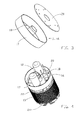
- the brushless direct current motor shown therein comprises a deep drawn housing 10, a rotor 11 including a shaft 12 having a flat 12 a at the end projecting from the closed end of the housing 10, a wound stator 13 surrounding the rotor 11, an end cap 14 closing the open end of the housing 10, and a container 16 within the housing 10 for sensors and electronic circuitry.
- the wound stator 13 comprises a stator winding 19 wound about a stack of stator laminations 30.
- the motor has an overall appearance similar to that of a conventional permanent magnet direct current motor having commutating parts comprising a commutator and brush/leaf system.
- the motor has particular application as a fuel pump motor, but also has other uses.
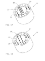
- the container 16 comprises a cylindrical bowl 17 having an integral sleeve 18 upstanding from the base of the bowl.
- the container is typically formed of Polyacetal (POM) and contains sensors, typically in the form of Hall-effect sensors, for sensing the position of the rotor 11 relative to the stator 13 and electronic circuitry mounted on an annular printed circuit board 20 which fits over the upstanding sleeve 18.
- the Hall-effect sensors lie flat on the printed circuit board 20. This is advantageous as compared to conventional "standing" hall sensors because it is easier to assemble and more reliable against fuel and vibrations after full encapsulation. Also, it allows a reduction in distance between the sensors and the planar top surface of the permanent magnet rotor.
- the circuitry switches the current in the stator windings in known manner in response to outputs from the sensors to cause the rotor to rotate relative to the stator.
- the sensors and electronic circuitry are then encapsulated in electrically insulating material, typically epoxy resin, which fills or substantially fills the container 16.
- electrically insulating material typically epoxy resin
- the sleeve 18 is dimensioned such as to allow the rotor shaft 12 to extend therethrough and to allow fuel from the fuel pump to flow therethrough.
- the sensors and most of the electronic components are fully encapsulated. Only such parts as, for example, electrical terminals and/or large capacitors will not be encapsulated fully.
- the underside of the base of the bowl 17 has four insulation displacement connectors 21 for direct connection to windings of the stator 13.
- the thermal conductivity of the encapsulating material may not be too important because of the cooling effect of fuel passing through the sleeve 18.
- Figure 6 shows in detail a front insulator 22 which is placed on the stator and which has the same number of slots 23 (four in this example) for receiving the stator windings and the insulation displacement connections 21 on the container 16.
- the internal bottom surface of the container 16 could have an electrically conductive pattern imprinted thereon.
- This can take the form of a heat-press foil applied with a heat-press stamp. All electronic components can then be automatically assembled on the bowl's inner surface and subsequently encapsulated.
- Another advantage of this technique is a further reduction in the distance between hall sensors and the planar top surface of rotor's magnet resulting in increased magnet field strength for position detection.
- the motor also has a rear insulator 24 similar to but not identical to the front insulator 22.
- the end cap 14 is connected to the housing 10 such as by crimping the rim of the housing 10 on the end cap at e.g. two positions.
- This end cap 14 supports or defines a bearing for the rotor shaft 12 and also includes integral features needed for a customer's fuel pump.
- a termination 26 is provided on the end cap 14 for connection to an external supply.
- a sleeve 15 is provided at the other end of the motor.
- the sleeve 15 is typically formed of Polyphenylensulfide (PPS). This material has a high heat dimensional stability, low elongation and extremely good resistance against all kinds of aggressive fuels.
- PPS Polyphenylensulfide
- the sleeve 15 supports or defines a bearing for the rotor shaft 12 and is also for attachment to a customer's fuel pump by press fitting into a hole in the fuel pump housing. Conventionally, the sleeve 15 has been part of the pump housing. It is now a part of the motor and serves the duel purpose of supporting or defining a bearing for the rotor shaft 12 and as a connecting/aligning element for the pump housing and allows the motor to be fully tested before supply to a customer.
- the sleeve 15 is the sole means of aligning the pump impeller and the rotor 11 of the motor.
- the rotor comprises a rotor shaft 12 and a laminated core 27 overmoulded with material 33 magnetised subsequent to moulding.
- the laminated core 27 comprises a plurality of rotor laminations 29. As shown in Figure 9, these laminations are stamped from sheet metal and maybe stamped at the same time as stator laminations 30.
- the rotor laminations 29 have three equi-angularly spaced, radially inwardly extending, slots 31 and a central aperture 32 for mounting the laminations on the rotor shaft 12.
- a stack of these laminations 30 are overmoulded with magnetisable material 33, typically thermoplastical bonded NdFeB compound and this (isotropic) material 33 is magnetised (as shown in Figure 7) subsequent to moulding.
- the overmoulding may also include an integral ring 34 which can be charged like an encoding disc to give a higher magnetic field strength in the axial direction (necessary for the Hall sensors).
- a rotor formed in this manner does not require any glue and is simple to assemble. Also no balancing is needed.
- the moulding material 33 also fills the slots 31.
- Figure 10 shows an alternative rotor lamination having six apertures 35 therein. These apertures 35 are equi-angularly spaced and three of the apertures are larger than the others. This reduces the weight of the rotor core 27 although, preferably, in order to avoid fuel pump rotor punch losses (i.e. losses due to turbulences of rotor in the fluid) the end laminations preferably have no such apertures 35.
- Figure 11 shows yet a further rotor lamination having no slots 31 but an uneven, knurled peripheral surface and six apertures 35' of equal dimensions.
- stator laminations 30 shown in Figure 9 are stamped at the same as the rotor laminations and comprise an outer ring 36, four equi-angularly spaced, radially inwardly extending pole pieces 37 around which windings (not shown) are wound and four flux pieces between the pole pieces 37.
- a stack of these laminations is difficult to wind because of the small gaps between the pole shoes 37 and the flux pieces 38. Also, external coil winding around pole pieces with subsequent insertion onto outer ring is not recommended for small-sized motors.
- an alternative stator 13' has an outer ring 36', a plurality of angularly spaced pole pieces 37' extending radially inwardly from the outer ring 36' and a plurality of flux pieces 38' between the pole pieces 37'.
- the flux pieces 38' are separate from the ring 36' and pole pieces 37' and are slidable into slots 39 defined by the outer ring 36' subsequent to winding of the pole pieces 37'. This simplifies the winding process and allows the flux pieces 38 to be optimally shaped.
- the ring 36' and pole pieces 37' are integrally formed and could be formed of stamped laminations secured together such as by laser welding/package punching or more preferably are formed in a unitary construction by moulding soft-magnetic sintered material.
- Figure 14 shows another embodiment of a motor in combination with a fuel pump 40 having an impeller 41.
- the motor is a conventional PMDC motor having a commutator 42 and brush system 43.
- an outer housing 45 accommodating the motor and the fuel pump 40.
- the pump body is press fitted into one end of the outer housing 45 to form a seal at the pump end of the outer housing and there is an O-ring seal 46 at the other end between an output cap 47 and the outer housing 45.
- There will be a similar arrangement accommodating the brushless motor of Figures 1 to 13 and the fuel pump.
- the rotor could surround the stator, more particularly when used as fan motors or storage drives.
Landscapes
- Engineering & Computer Science (AREA)
- Power Engineering (AREA)
- Combustion & Propulsion (AREA)
- Mechanical Engineering (AREA)
- General Engineering & Computer Science (AREA)
- Microelectronics & Electronic Packaging (AREA)
- Chemical & Material Sciences (AREA)
- Brushless Motors (AREA)
- Iron Core Of Rotating Electric Machines (AREA)
- Structures Of Non-Positive Displacement Pumps (AREA)
- Connection Of Motors, Electrical Generators, Mechanical Devices, And The Like (AREA)
- Permanent Field Magnets Of Synchronous Machinery (AREA)
- Glass Compositions (AREA)
- Manufacture Of Motors, Generators (AREA)
- Permanent Magnet Type Synchronous Machine (AREA)
- Control Of Motors That Do Not Use Commutators (AREA)
- Valve Device For Special Equipments (AREA)
- Transition And Organic Metals Composition Catalysts For Addition Polymerization (AREA)
- Motor Or Generator Frames (AREA)
Abstract
Description
Claims (10)
- A motor comprising a stator (13), a rotor (11), and a sleeve (15) at one end of the motor for supporting or defining a bearing for the rotor and for attachment to a fuel pump.
- A motor as claimed in claim 1, wherein the sleeve (15) forms the sole means of aligning the rotor and an impeller (41) of the pump.
- A motor as claimed in claim 1, wherein the stator (13) surrounds the rotor (11).
- A motor as claimed in any one of claims 1 to 3, further comprising windings (19) on the stator, sensors for sensing the position of the rotor relative to the stator, electronic circuitry for switching the current in the windings in response to outputs from the sensors so as to cause the rotor to rotate relative to the stator and a housing (10) containing the rotor, the stator, the sensors and the electronic circuitry.
- A motor as claimed in claim 4, wherein the sensors and at least part of the electronic circuitry are encapsulated in an electrically insulating and fuel resistant material in a container (16) within the housing (10).
- A motor as claimed in claim 5, wherein the container (16) has an internal sleeve (18) through which a shaft (12) of the rotor extends and through which fuel from the fuel pump can flow.
- A motor as claimed in any one of the preceding claims in combination with a fuel pump (40).
- The combination as claimed in claim 7, wherein an outer housing (45) accommodates the motor and the fuel pump (40).
- The combination as claimed in claim 8, wherein there is a gap between the motor and the outer housing (45) to allow for alignment of the motor and the pump.
- The combination as claimed in claim 9, wherein the fuel pump (40) is a press fit in the outer housing (45) to form a seal at the pump end of the outer housing.
Applications Claiming Priority (2)
| Application Number | Priority Date | Filing Date | Title |
|---|---|---|---|
| GBGB0130602.6A GB0130602D0 (en) | 2001-12-21 | 2001-12-21 | Brushless D.C. motor |
| GB0130602 | 2001-12-21 |
Publications (3)
| Publication Number | Publication Date |
|---|---|
| EP1324465A2 true EP1324465A2 (en) | 2003-07-02 |
| EP1324465A3 EP1324465A3 (en) | 2005-06-22 |
| EP1324465B1 EP1324465B1 (en) | 2006-11-02 |
Family
ID=9928126
Family Applications (3)
| Application Number | Title | Priority Date | Filing Date |
|---|---|---|---|
| EP06016904A Withdrawn EP1720235A3 (en) | 2001-12-21 | 2002-12-13 | Brushless D.C. motor |
| EP02258614A Expired - Lifetime EP1324465B1 (en) | 2001-12-21 | 2002-12-13 | An electric motor |
| EP02258610A Expired - Lifetime EP1324474B1 (en) | 2001-12-21 | 2002-12-13 | Brushless D.C. motor |
Family Applications Before (1)
| Application Number | Title | Priority Date | Filing Date |
|---|---|---|---|
| EP06016904A Withdrawn EP1720235A3 (en) | 2001-12-21 | 2002-12-13 | Brushless D.C. motor |
Family Applications After (1)
| Application Number | Title | Priority Date | Filing Date |
|---|---|---|---|
| EP02258610A Expired - Lifetime EP1324474B1 (en) | 2001-12-21 | 2002-12-13 | Brushless D.C. motor |
Country Status (10)
| Country | Link |
|---|---|
| US (3) | US7057318B2 (en) |
| EP (3) | EP1720235A3 (en) |
| JP (3) | JP4414647B2 (en) |
| CN (3) | CN100342626C (en) |
| AT (2) | ATE413008T1 (en) |
| BR (2) | BR0205069A (en) |
| DE (2) | DE60229615D1 (en) |
| ES (2) | ES2316527T3 (en) |
| GB (1) | GB0130602D0 (en) |
| MX (3) | MXPA02012632A (en) |
Cited By (17)
| Publication number | Priority date | Publication date | Assignee | Title |
|---|---|---|---|---|
| WO2007063976A1 (en) * | 2005-11-29 | 2007-06-07 | Matsushita Electric Industrial Co., Ltd. | Motor |
| WO2008133600A1 (en) * | 2007-05-01 | 2008-11-06 | Superpar Otomotiv San. Ve Tic. A. S. | Novelty in electric fuel pumps for internal combustion engines |
| EP2182616A2 (en) | 2008-11-04 | 2010-05-05 | KNF Neuberger GmbH | Brushless DC motor |
| EP1737105A3 (en) * | 2005-06-20 | 2010-06-23 | LG Electronics Inc. | Rotor of motor and manufacturing method thereof |
| WO2010118487A3 (en) * | 2009-04-17 | 2011-01-20 | Robert Bosch Limitada | A housing for the control electronics of a brushless direct- current motor |
| CN1676915B (en) * | 2004-04-02 | 2011-03-02 | 株式会社电装 | Fuel supply equipment |
| EP1850455A3 (en) * | 2006-04-25 | 2011-11-23 | LG Electronics Inc. | Rotor of electric motor for simplifying manufacturing process and electric motor having the same |
| EP2475075A1 (en) * | 2011-01-05 | 2012-07-11 | Robert Bosch GmbH | Motor construction |
| EP1884010A4 (en) * | 2005-05-17 | 2013-02-27 | Federal Mogul Corp | DIRECT CURRENT MOTOR WITHOUT SLIDING CONTACTS AND PUMP ASSEMBLY COMPRISING AN ENCAPSULATED PRINTED CIRCUIT BOARD |
| WO2013037535A1 (en) * | 2011-09-13 | 2013-03-21 | Robert Bosch Gmbh | Gear pump and method for producing a gear pump |
| EP2387131A3 (en) * | 2010-05-10 | 2013-08-14 | Makita Corporation | Brushless DC motor |
| EP3118869A1 (en) * | 2015-07-03 | 2017-01-18 | Jtekt Corporation | Manufacturing method of rotor and rotor |
| EP3118870A1 (en) * | 2015-07-03 | 2017-01-18 | Jtekt Corporation | Manufacturing method of rotor and rotor |
| EP3168963A4 (en) * | 2014-07-08 | 2018-03-28 | Mitsubishi Electric Corporation | Rotor of electric motor, molded electric motor, and air conditioning unit |
| EP3312973A4 (en) * | 2015-09-18 | 2018-09-12 | Aisin AW Co., Ltd. | Rotating electric machine and stator |
| DE102017223514A1 (en) | 2017-12-21 | 2019-06-27 | Adient Aerospace Llc | Electromechanical drive unit for controlling a moving part of an adjusting unit and adjusting unit |
| WO2020173913A1 (en) * | 2019-02-25 | 2020-09-03 | Nidec Gpm Gmbh | Electric contacting of stator connections on a printed circuit board by means of horizontally oriented insulation displacement contacts |
Families Citing this family (134)
| Publication number | Priority date | Publication date | Assignee | Title |
|---|---|---|---|---|
| JP4408674B2 (en) * | 2003-09-29 | 2010-02-03 | 愛三工業株式会社 | Fuel pump |
| GB0327023D0 (en) * | 2003-11-20 | 2003-12-24 | Head Philip | Electric motors for powering downhole tools |
| DE10356078A1 (en) * | 2003-12-01 | 2005-06-23 | Siemens Ag | Engine for a fuel pump |
| JP4613596B2 (en) * | 2004-04-02 | 2011-01-19 | 株式会社デンソー | Fuel supply device |
| US7737598B2 (en) | 2004-08-09 | 2010-06-15 | A. O. Smith Corporation | Electric motor having a stator |
| US7247967B2 (en) | 2004-08-09 | 2007-07-24 | A. O. Smith Corporation | Electric motor having a stator |
| CN101356373B (en) * | 2004-11-23 | 2013-07-17 | 恩特格里公司 | System for position control of a mechanical piston in a pump |
| US8292598B2 (en) | 2004-11-23 | 2012-10-23 | Entegris, Inc. | System and method for a variable home position dispense system |
| JP2006299954A (en) * | 2005-04-21 | 2006-11-02 | Hitachi Ltd | Fuel pump |
| KR100653434B1 (en) * | 2005-04-29 | 2006-12-01 | 영 춘 정 | 2-phase rectifier motor |
| EP1908162B1 (en) * | 2005-07-26 | 2013-03-20 | ebm-papst St. Georgen GmbH & Co. KG | Brushless electric motor |
| JP4696855B2 (en) * | 2005-11-02 | 2011-06-08 | 株式会社デンソー | Fuel pump |
| US8753097B2 (en) | 2005-11-21 | 2014-06-17 | Entegris, Inc. | Method and system for high viscosity pump |
| KR101308784B1 (en) | 2005-11-21 | 2013-09-17 | 엔테그리스, 아이엔씨. | System and method for a pump with reduced form factor |
| JP5339915B2 (en) * | 2005-11-21 | 2013-11-13 | インテグリス・インコーポレーテッド | Piston control system and method for pump mechanical piston |
| WO2007062766A1 (en) * | 2005-12-01 | 2007-06-07 | Emb-Papst St. Georgen Gmbh & Co. Kg | Electric motor |
| KR101243509B1 (en) | 2005-12-02 | 2013-03-20 | 엔테그리스, 아이엔씨. | System and method for pressure compensation in a pump |
| US8083498B2 (en) | 2005-12-02 | 2011-12-27 | Entegris, Inc. | System and method for position control of a mechanical piston in a pump |
| US7878765B2 (en) | 2005-12-02 | 2011-02-01 | Entegris, Inc. | System and method for monitoring operation of a pump |
| TWI402423B (en) | 2006-02-28 | 2013-07-21 | Entegris Inc | System and method for operation of a pump |
| US7566999B2 (en) * | 2006-07-19 | 2009-07-28 | Encap Technologies Inc. | Electromagnetic device with composite structure heat transfer flow path |
| US7931448B2 (en) | 2006-08-01 | 2011-04-26 | Federal Mogul World Wide, Inc. | System and method for manufacturing a brushless DC motor fluid pump |
| US20080073986A1 (en) * | 2006-09-26 | 2008-03-27 | Lg Electronics Inc. | Permanent magnet rotor type motor and method for manufacturing the same |
| ATE489901T1 (en) * | 2007-01-17 | 2010-12-15 | W & H Dentalwerk Buermoos Gmbh | MEDICAL HANDLE |
| US8253285B2 (en) | 2007-04-27 | 2012-08-28 | Hitachi Koki Co., Ltd. | Power tool |
| JP4974054B2 (en) * | 2007-04-27 | 2012-07-11 | 日立工機株式会社 | Electric tool |
| US7847457B2 (en) | 2007-05-09 | 2010-12-07 | Federal-Mogul World Wide, Inc | BLDC motor assembly |
| US8299661B2 (en) | 2007-05-11 | 2012-10-30 | Sntech Inc. | Rotor of brushless motor |
| US8033007B2 (en) | 2007-05-11 | 2011-10-11 | Sntech, Inc. | Method of making rotor of brushless motor |
| US8384257B2 (en) * | 2007-05-25 | 2013-02-26 | Mitsubishi Electric Corporation | Brushless motor |
| US7874817B2 (en) * | 2007-06-01 | 2011-01-25 | Ti Group Automotive Systems, L.L.C. | Fuel pump assembly with a vapor purge passage arrangement for a fuel pump module |
| US7960931B2 (en) * | 2007-06-15 | 2011-06-14 | Illinois Institute Of Technology | Digital control of motor drives |
| FR2919971B1 (en) * | 2007-08-06 | 2009-10-16 | Leroy Somer Moteurs | ELECTRIC GENERATOR AND INSTALLATION COMPRISING A LIGHTING TOWER SUPPLIED BY SUCH A GENERATOR |
| DE202007018933U1 (en) * | 2007-10-02 | 2009-11-12 | Kolektor Kautt & Bux Gmbh | Winding connection device for an electric motor or generator |
| CN201118414Y (en) * | 2007-10-29 | 2008-09-17 | 深圳航天科技创新研究院 | Square wave three-phase brushless permanent magnet DC motor |
| KR100946719B1 (en) * | 2007-11-28 | 2010-03-12 | 영 춘 정 | Multi-programmable constant flow control device of variable speed non-commutator motor |
| US7795827B2 (en) * | 2008-03-03 | 2010-09-14 | Young-Chun Jeung | Control system for controlling motors for heating, ventilation and air conditioning or pump |
| WO2009126853A2 (en) * | 2008-04-11 | 2009-10-15 | Cooper Standard Automotive, Inc. | Rotor assembly including sintered magnet core assembly |
| US20090284201A1 (en) * | 2008-05-15 | 2009-11-19 | Young-Chun Jeung | Motor with magnetic sensors |
| WO2009158359A2 (en) * | 2008-06-23 | 2009-12-30 | Sntech, Inc. | Data transfer between motors |
| US20100039055A1 (en) * | 2008-08-14 | 2010-02-18 | Young-Chun Jeung | Temperature control of motor |
| US8138710B2 (en) * | 2008-08-14 | 2012-03-20 | Sntech Inc. | Power drive of electric motor |
| CN101666279B (en) * | 2008-09-03 | 2014-02-19 | 德昌电机(深圳)有限公司 | fuel pump |
| DE102009013374B4 (en) * | 2009-03-07 | 2019-08-14 | Ziehl-Abegg Se | Rotor for electric motors, permanent magnet for such a rotor and electric machine with a rotor |
| DE102009001808A1 (en) * | 2009-03-24 | 2010-09-30 | Robert Bosch Gmbh | electric motor |
| US8232755B2 (en) | 2009-04-02 | 2012-07-31 | Young-Chun Jeung | Motor with circuits for protecting motor from input power outages or surges |
| DE102009024014A1 (en) * | 2009-06-05 | 2010-12-09 | Minebea Co., Ltd., Miyota-machi | Rotor for permanent magnet motor, has shaft and rotor body which is connected with shaft in rotably fixed manner, where anisotropic multipolar drive magnet is formed at rotor body |
| KR101041165B1 (en) * | 2009-07-14 | 2011-06-13 | 엘지이노텍 주식회사 | Stator core of the motor |
| WO2011022557A2 (en) * | 2009-08-19 | 2011-02-24 | Aspen Motion Technologies, Inc. D/B/A | Magnetic drive pump assembly with integrated motor |
| KR101098748B1 (en) * | 2009-10-01 | 2011-12-23 | (주) 디에이치홀딩스 | Brushless DC motor for fuel pump |
| KR101134970B1 (en) | 2009-11-19 | 2012-04-09 | 현대자동차주식회사 | Electric water pump |
| KR101134969B1 (en) | 2009-11-19 | 2012-04-09 | 현대자동차주식회사 | Method for manufacturing stator for electric water pump |
| KR101134968B1 (en) | 2009-11-19 | 2012-04-09 | 현대자동차주식회사 | Electric water pump |
| JP2011167024A (en) * | 2010-02-15 | 2011-08-25 | Minebea Co Ltd | Dc brushless motor device |
| US8378618B2 (en) * | 2010-02-19 | 2013-02-19 | Sntech, Inc. | Systems and methods for controlling operations of a motor |
| US20130134803A1 (en) | 2010-03-05 | 2013-05-30 | Andreas Kappel | Electromechanical motor |
| US20110274556A1 (en) * | 2010-05-04 | 2011-11-10 | Adda Corporation | Positioning structure for stator assembly of cooling fan |
| CN102237760A (en) * | 2010-05-07 | 2011-11-09 | 上海宝钢汽车检测修复有限公司 | Motor of electrically-driven coach car |
| KR101115498B1 (en) * | 2010-05-19 | 2012-02-27 | 성장연 | Brushless DC Motor |
| EP2580850B1 (en) * | 2010-06-14 | 2021-11-10 | Black & Decker, Inc. | Control unit for brushless motor in a power tool |
| CN201774430U (en) * | 2010-07-29 | 2011-03-23 | 中山大洋电机制造有限公司 | A new motor mechanism |
| JP5229642B2 (en) * | 2010-08-06 | 2013-07-03 | 株式会社デンソー | Motor and electric power steering apparatus using the same |
| US9138818B2 (en) * | 2010-08-16 | 2015-09-22 | Emerson Electric Co. | Systems and devices for performing powered threading operations |
| DE102011110752A1 (en) | 2010-08-20 | 2012-03-15 | Johnson Electric S.A. | Brushless motor |
| US8581466B2 (en) | 2010-08-27 | 2013-11-12 | Hamilton Sundstrand Corporation | Knurled multiple conductor windings |
| CN101951109B (en) * | 2010-10-12 | 2012-03-28 | 彭希南 | Direct Drive Permanent Magnet Brushless DC Motor |
| DE102010049054A1 (en) * | 2010-10-15 | 2012-04-19 | Ziehl-Abegg Ag | Rotor i.e. internal rotor, for electronically commutated internal electric motor, has permanent magnets arranged one behind other in non-uniform spacings for formation of pole gaps spaced along circumferential direction |
| TW201233005A (en) * | 2011-01-18 | 2012-08-01 | Yen Shen Electric Ind Co Ltd | Motor rotor capable of being separately applied to two magnetic units |
| US9509180B2 (en) * | 2011-01-26 | 2016-11-29 | Makita Corporation | Brushless motor for electric power tool |
| CN201947080U (en) * | 2011-01-28 | 2011-08-24 | 中山大洋电机制造有限公司 | A brushless motor rotor structure |
| WO2012156079A2 (en) | 2011-05-15 | 2012-11-22 | Wild, Ulrich | Rotary drive |
| CN102213151A (en) * | 2011-05-17 | 2011-10-12 | 遵义天义利威机电有限责任公司 | Controller of non-position sensor direct current brushless electric fuel pump for automobile |
| DE102011084702A1 (en) * | 2011-10-18 | 2013-04-18 | Continental Automotive Gmbh | Method of making a BLDC motor |
| US8896169B2 (en) | 2011-10-31 | 2014-11-25 | Regal Beloit America, Inc. | Methods and apparatus for mounting a motor controller on a stator assembly |
| KR200463261Y1 (en) | 2011-11-29 | 2012-10-25 | 금산전자 주식회사 | Connector deveic for brushless motor |
| US20130140938A1 (en) * | 2011-12-05 | 2013-06-06 | GM Global Technology Operations LLC | Balanced rotor core with reduced mass and inertia laminations |
| US8679210B2 (en) | 2012-01-17 | 2014-03-25 | Hamilton Sundstrand Corporation | Shrouded particle separator |
| WO2013127626A2 (en) * | 2012-02-27 | 2013-09-06 | Ixetic Bad Homburg Gmbh | Pump arrangement |
| DE102012209905A1 (en) * | 2012-06-13 | 2013-12-19 | Krones Ag | Capper for containers |
| EP2674256B1 (en) * | 2012-06-15 | 2021-11-10 | Black & Decker Inc. | Brushless motor commutation control in a power tool |
| EP2863061B1 (en) * | 2012-06-19 | 2020-11-25 | Mitsubishi Electric Corporation | Pump, method for manufacturing pump, and refrigeration cycle device |
| DE102012211183A1 (en) * | 2012-06-28 | 2014-01-02 | Robert Bosch Gmbh | Power tool |
| DE102012213051A1 (en) * | 2012-07-25 | 2014-01-30 | Robert Bosch Gmbh | Hand tool |
| TWI584905B (en) * | 2012-07-27 | 2017-06-01 | 鴻準精密工業股份有限公司 | Method for manufacturing fan impeller |
| JP2014042441A (en) * | 2012-08-22 | 2014-03-06 | Samsung Electro-Mechanics Co Ltd | Switched reluctance motor assembly |
| US9169833B2 (en) | 2012-10-04 | 2015-10-27 | Carter Fuel Systems, Llc | Device for fastening and electrically connecting a circuit board to a motor |
| KR101245176B1 (en) | 2012-10-19 | 2013-03-25 | 송병로 | Moter by using coil winding of etching foil type |
| EP2915224B1 (en) * | 2012-11-01 | 2024-03-13 | Smiths Interconnect Americas, Inc. | Rotary electrical interconnect device |
| US10821591B2 (en) | 2012-11-13 | 2020-11-03 | Milwaukee Electric Tool Corporation | High-power cordless, hand-held power tool including a brushless direct current motor |
| JP2014103721A (en) * | 2012-11-16 | 2014-06-05 | Aisin Seiki Co Ltd | Brushless motor |
| KR101482939B1 (en) | 2013-08-20 | 2015-01-15 | 박정희 | Hall Sensor Fastening Structure of BLDC Motor |
| TWI516000B (en) * | 2013-08-20 | 2016-01-01 | 林聖梁 | Motor |
| US9712002B2 (en) * | 2013-08-23 | 2017-07-18 | Magna Powertrain Bad Homburg GmbH | Interlocked stator yoke and star for electric motor |
| JP6275415B2 (en) * | 2013-08-29 | 2018-02-07 | 東京パーツ工業株式会社 | Brushless motor |
| JP6234128B2 (en) | 2013-09-11 | 2017-11-22 | 株式会社マキタ | Electric tool |
| CN103590941A (en) * | 2013-10-24 | 2014-02-19 | 安徽工贸职业技术学院 | Anticorrosive fuel pump |
| DE102013222534A1 (en) * | 2013-11-06 | 2015-05-07 | Robert Bosch Gmbh | electric machine |
| US10253676B2 (en) | 2013-12-20 | 2019-04-09 | Magna Powertrain Bad Homburg GmbH | Molded rotor for cooling fan motor |
| CN105099013B (en) * | 2014-04-23 | 2019-05-03 | 德昌电机(深圳)有限公司 | The motor of motor stator component and the application stator module |
| US9759236B2 (en) | 2014-04-25 | 2017-09-12 | Hamilton Sundstrand Corporation | Inlet tube design |
| CN104033351A (en) * | 2014-07-01 | 2014-09-10 | 江苏恒康机电有限公司 | Oil pump motor set for multi-pump hydraulic system |
| EP2991195A1 (en) * | 2014-09-01 | 2016-03-02 | Siemens Aktiengesellschaft | Permanently excited dynamoelectric machine |
| US10224779B2 (en) * | 2014-10-02 | 2019-03-05 | Regal Beloit America, Inc. | Electric machine, barrier and associated kit |
| US10523081B2 (en) | 2014-11-25 | 2019-12-31 | Black & Decker Inc. | Brushless motor for a power tool |
| US10693344B2 (en) | 2014-12-18 | 2020-06-23 | Black & Decker Inc. | Packaging of a control module for a brushless motor |
| KR101697704B1 (en) * | 2015-05-27 | 2017-01-19 | 디와이오토 주식회사 | Stator apparatus for brushless motor |
| JP6308177B2 (en) * | 2015-06-26 | 2018-04-11 | 株式会社デンソー | Rotor |
| CN105071625A (en) * | 2015-07-31 | 2015-11-18 | 常州市昊升电机有限公司 | Novel high-speed brushless motor |
| US10786894B2 (en) | 2015-10-14 | 2020-09-29 | Black & Decker Inc. | Brushless motor system for power tools |
| EP3176923B1 (en) * | 2015-10-20 | 2020-01-01 | Mitsubishi Electric Corporation | Electric motor rotor manufacturing method and manufacturing device |
| US10308307B2 (en) * | 2016-02-16 | 2019-06-04 | Allied Treasure Inc., Limited | Disk-type electric motor, electrically driven vehicle and method for controlling the same |
| CN110912341B (en) | 2016-03-30 | 2022-03-18 | 米沃奇电动工具公司 | Brushless motor for electric tool |
| DE102016205252A1 (en) * | 2016-03-30 | 2017-10-05 | Mahle International Gmbh | Bearing arrangement of a motor shaft of an electric motor |
| CN109075649B (en) * | 2016-04-12 | 2020-10-16 | 翰昂汽车零部件德国有限公司 | Drive device |
| TWI654370B (en) * | 2016-06-15 | 2019-03-21 | 泓記精密股份有限公司 | Electric fuel pump |
| CN106337824B (en) * | 2016-09-28 | 2018-10-23 | 浙江亿利达风机股份有限公司 | A kind of volute casing centrifugal blower fan of novel belt permanent magnetic brushless system |
| CN106194770B (en) * | 2016-09-30 | 2019-05-07 | 克奥兹泵业(深圳)有限公司 | Small Minitype centrifugal water pump |
| DE102017107612A1 (en) * | 2017-04-10 | 2018-10-11 | Valeo Systèmes d'Essuyage | Brushless electric motor and method of manufacturing the electric motor |
| US10840776B2 (en) | 2017-05-27 | 2020-11-17 | Actuator Electric Motors | Self-contained brushless motor and brushless controller |
| DE102017209621A1 (en) * | 2017-06-08 | 2018-12-13 | Robert Bosch Gmbh | Drive unit with an electronically commutated motor and an electronics unit |
| DE102017121215A1 (en) * | 2017-09-13 | 2019-03-14 | Valeo Systèmes d'Essuyage | Brushless electric motor |
| CN109256884A (en) * | 2017-10-13 | 2019-01-22 | 朱卫 | A kind of motor case produced with titanium |
| JP2019106778A (en) * | 2017-12-12 | 2019-06-27 | 東京パーツ工業株式会社 | Motor and actuator unit |
| US11139722B2 (en) | 2018-03-02 | 2021-10-05 | Black & Decker Inc. | Motor having an external heat sink for a power tool |
| DE102018219359A1 (en) * | 2018-11-13 | 2020-05-14 | Zf Friedrichshafen Ag | Electric drive unit and transmission for a motor vehicle |
| CN109555718A (en) * | 2019-01-24 | 2019-04-02 | 全小华 | High-speed permanent-magnet brushless axial flow blower |
| US11462981B2 (en) | 2019-08-28 | 2022-10-04 | Hossam Abdou | Electric motor |
| EP3829041A1 (en) | 2019-11-29 | 2021-06-02 | Hilti Aktiengesellschaft | Hall board within winding heads |
| DE102020202781A1 (en) * | 2020-03-04 | 2021-09-09 | Siemens Aktiengesellschaft | 8Electric motor with can |
| US20220200401A1 (en) | 2020-12-23 | 2022-06-23 | Black & Decker Inc. | Brushless dc motor with circuit board for winding interconnections |
| KR20220118907A (en) | 2021-02-19 | 2022-08-26 | 제이엔씨 주식회사 | Liquid crystal composition and liquid crystal display device |
| US12068639B2 (en) | 2021-06-07 | 2024-08-20 | Black & Decker Inc. | Motor rotor with sleeve for retention of magnet ring |
| US11916447B2 (en) * | 2021-06-07 | 2024-02-27 | Black & Decker Inc. | Overmolded rotor structure |
| CN113241902B (en) * | 2021-06-29 | 2022-08-26 | 中汽创智科技有限公司 | Motor and braking system |
Family Cites Families (81)
| Publication number | Priority date | Publication date | Assignee | Title |
|---|---|---|---|---|
| US3644067A (en) * | 1970-05-25 | 1972-02-22 | Sperry Rand Corp | Power transmission |
| GB1340800A (en) * | 1971-10-18 | 1973-12-12 | Gen Motors Corp | Electric fuel pump assemblies |
| US3873861A (en) * | 1973-06-15 | 1975-03-25 | Richard Halm | Electric motor, especially a squirrel-cage motor |
| DE2628729A1 (en) | 1976-06-25 | 1978-01-05 | Teldix Gmbh | Brushless DC motor with internal stator - has plug connections between machine and electronic control circuits |
| US4186319A (en) | 1977-04-26 | 1980-01-29 | General Electric Company | Dynamoelectric machine end shield |
| JPS57148567A (en) * | 1981-03-09 | 1982-09-13 | Hitachi Metals Ltd | Cylindrical magnet and manufacture thereof |
| DE3126100A1 (en) * | 1981-07-02 | 1983-01-20 | Robert Bosch Gmbh, 7000 Stuttgart | Device for mounting and cooling a power transistor |
| US4508492A (en) * | 1981-12-11 | 1985-04-02 | Nippondenso Co., Ltd. | Motor driven fuel pump |
| US5418416A (en) * | 1983-09-05 | 1995-05-23 | Papst Licensing Gmbh | Brushless three-phase DC motor |
| US4504755A (en) | 1983-11-03 | 1985-03-12 | Kollmorgen Technologies Corporation | Rotor reluctance notch for cogging control |
| JPH0744795B2 (en) * | 1984-03-09 | 1995-05-15 | 松下電器産業株式会社 | Non-commutator motor rotor |
| GB2157766B (en) * | 1984-04-25 | 1988-01-20 | Facet Enterprises | Rotary fuel-pump for an i.c.engine |
| JPS61280752A (en) * | 1985-06-05 | 1986-12-11 | Oopack Kk | Brushless dc rotary electric machine |
| JPH0442559Y2 (en) * | 1985-10-03 | 1992-10-07 | ||
| JPS62235523A (en) * | 1986-03-19 | 1987-10-15 | Honda Motor Co Ltd | Manufacture of rotational angle sensor |
| JPS61210857A (en) * | 1986-03-19 | 1986-09-19 | Hitachi Ltd | permanent magnet synchronous motor |
| WO1987007097A1 (en) | 1986-05-12 | 1987-11-19 | Henck Ronald W | Electric motor and method for manufacturing the same |
| US4789308A (en) * | 1986-10-10 | 1988-12-06 | Walbro Corporation | Self-contained electric fuel pump with output pressure regulation |
| US4737674A (en) * | 1986-10-17 | 1988-04-12 | Shicoh Engineering Co., Ltd. | Single phase brushless motor with a core |
| DE3710658A1 (en) * | 1987-03-31 | 1988-10-13 | Standard Elektrik Lorenz Ag | ELECTRONICALLY COMMUTED, COLLECTORLESS DC MOTOR |
| JPH0828293B2 (en) * | 1987-04-07 | 1996-03-21 | 日立金属株式会社 | Cylindrical permanent magnet, motor using the same, and manufacturing method thereof |
| GB2217924B (en) * | 1988-04-25 | 1992-10-07 | Matsushita Electric Works Ltd | Permanent magnet rotor |
| IT1220410B (en) * | 1988-06-29 | 1990-06-15 | Gd Spa | DEVICE FOR DRILLING PERFORATIONS IN BAR-SHAPED ITEMS |
| US4998865A (en) * | 1988-07-11 | 1991-03-12 | Aisan Kogyo Kabushiki Kaisha | Brushless DC pump with enclosed circuit board |
| US5053664A (en) * | 1989-01-18 | 1991-10-01 | Aisan Kogyo Kabushiki Kaisha | Motor-driven fuel pump |
| JPH02311147A (en) * | 1989-05-25 | 1990-12-26 | Seiko Epson Corp | Composite cylindrical permanent magnet |
| JPH0333494A (en) * | 1989-06-29 | 1991-02-13 | Mitsubishi Electric Corp | In-tank type motor-driven pump |
| SI8912097B (en) * | 1989-10-30 | 1999-04-30 | Iskra-Elektromotorji, P.O., | Single-phase direct current motor without brushes with high speed and high power |
| US5145614A (en) * | 1990-02-14 | 1992-09-08 | Canon Kabushiki Kaisha | Process for preparing magnet made of resin |
| ES2077723T5 (en) * | 1990-07-06 | 2000-03-01 | Hitachi Ltd | BRUSHLESS MOTOR THAT INCORPORATES AN INTEGRATED CIRCUIT THAT HAS A PERIPHERAL MONOCHIP CIRCUIT. |
| US5356272A (en) * | 1990-09-05 | 1994-10-18 | Nippondenso Co., Ltd. | Fuel supply device and method of assembling same |
| JP3123183B2 (en) | 1991-02-08 | 2001-01-09 | 株式会社デンソー | Vehicle fuel supply system |
| CN2121766U (en) * | 1991-07-16 | 1992-11-11 | 德昌电机股份有限公司 | Motor |
| US5221503A (en) * | 1991-10-28 | 1993-06-22 | General Motors Corporation | Method for manufacturing a dynamoelectric device |
| DE4201401A1 (en) * | 1992-01-21 | 1993-07-22 | Bosch Gmbh Robert | Displacement pump conveying fuel in motor vehicle - has drive motor installed into jar-shaped housing as complete prefabricated component of motor housing |
| JPH05207718A (en) | 1992-01-24 | 1993-08-13 | Nippon Densan Corp | DC motor |
| CN1031439C (en) * | 1992-03-18 | 1996-03-27 | 武昆山 | Three-phase induction motor |
| JPH05284678A (en) * | 1992-03-31 | 1993-10-29 | Mabuchi Motor Co Ltd | Miniature motor |
| JPH05292689A (en) * | 1992-04-06 | 1993-11-05 | Matsushita Electric Ind Co Ltd | Rotor of permanent magnet motor |
| US5402024A (en) * | 1992-04-06 | 1995-03-28 | Matsushita Electric Industrial Co., Ltd. | Rotor for a permanent-magnet motor |
| JPH06280707A (en) * | 1993-03-24 | 1994-10-04 | Aisan Ind Co Ltd | Electric motor-driven fuel pump |
| US5345130A (en) * | 1993-04-28 | 1994-09-06 | General Electric Company | Modable permanent magnet rotor for optimized field shaping |
| AU682393B2 (en) * | 1993-10-13 | 1997-10-02 | Ebara Corporation | Motor stator assembly and full-circumferential flow pump employing such motor stator assembly |
| KR0118819Y1 (en) * | 1993-11-30 | 1998-07-15 | 김광호 | Door opening and closing device of refrigerator |
| JPH07184339A (en) * | 1993-12-24 | 1995-07-21 | Asmo Co Ltd | Motor mounting structure |
| JPH07203645A (en) * | 1993-12-30 | 1995-08-04 | Mabuchi Motor Co Ltd | Manufacturing method of small motor and rotor thereof |
| US5393206A (en) * | 1994-06-29 | 1995-02-28 | General Motors Corporation | Fuel pump for a motor vehicle |
| JPH08126265A (en) | 1994-09-02 | 1996-05-17 | Sankyo Seiki Mfg Co Ltd | Rotating electric machine |
| US5961293A (en) * | 1995-05-19 | 1999-10-05 | Uis, Inc | In-take fuel pump assembly with unitary control unit for internal combustion engines |
| JP3487679B2 (en) * | 1995-06-14 | 2004-01-19 | 三洋電機株式会社 | Small electric motor |
| JPH09215236A (en) | 1996-02-06 | 1997-08-15 | Daikin Ind Ltd | Brushless DC motor |
| BR9601756A (en) * | 1996-05-29 | 1998-09-29 | Brasil Compressores Sa | Electric motor rotor cover |
| US5717268A (en) * | 1996-06-17 | 1998-02-10 | Philips Electronics North America Corp. | Electric motor with tachometer signal generator |
| DE19705974A1 (en) * | 1997-02-17 | 1998-08-20 | Wilo Gmbh | Electric motor for a pump or a fan |
| US6025665A (en) * | 1997-02-21 | 2000-02-15 | Emerson Electric Co. | Rotating machine for use in a pressurized fluid system |
| JPH10285895A (en) * | 1997-03-31 | 1998-10-23 | Kusatsu Denki Kk | Brushless motor rotor |
| KR19980075864A (en) * | 1997-04-02 | 1998-11-16 | 윤종용 | Brushless DC Motor |
| US5898990A (en) * | 1997-04-14 | 1999-05-04 | General Motors Corporation | Method of assembling a magnet ring on a rotor |
| US5920437A (en) * | 1997-05-08 | 1999-07-06 | Sankyo Seiki Mfg. Co., Ltd. | Objective lens driving apparatus |
| BR9702802A (en) * | 1997-08-28 | 2000-02-15 | Brasil Compressores Sa | Rotor for electric motor. |
| JPH11136889A (en) * | 1997-10-28 | 1999-05-21 | Toshiba Corp | Permanent magnet type motor and manufacturing method thereof |
| US5939807A (en) * | 1997-12-16 | 1999-08-17 | Reliance Electric Industrial Company | Cap mounted drive for a brushless DC motor |
| JPH11299207A (en) * | 1998-04-17 | 1999-10-29 | Matsushita Electric Ind Co Ltd | Brushless motor |
| JP3318531B2 (en) * | 1998-08-04 | 2002-08-26 | ミネベア株式会社 | Rotating electric machine and its bearing structure |
| DE19836451C2 (en) * | 1998-08-12 | 2000-05-31 | Baermann Max Gmbh | Highly filled plastic part |
| DE19842170A1 (en) * | 1998-09-15 | 2000-03-16 | Wilo Gmbh | Contacting motor windings |
| JP2000102201A (en) * | 1998-09-18 | 2000-04-07 | Toshiba Corp | Permanent magnet rotor and manufacturing method thereof |
| JP2000156963A (en) * | 1998-11-19 | 2000-06-06 | Moriyama Kogyo Kk | Magnetic pole position detecting device for brushless DC motor and annular sheet with thin plate magnet |
| DE19904162C2 (en) * | 1999-02-03 | 2000-11-23 | Pierburg Ag | Fuel electric motor pump |
| JP3881126B2 (en) * | 1999-03-05 | 2007-02-14 | アスモ株式会社 | motor |
| JP2000287430A (en) * | 1999-03-29 | 2000-10-13 | Matsushita Electric Ind Co Ltd | Brushless motor, pump using the same, and method of magnetizing brushless motor magnet |
| US6231318B1 (en) * | 1999-03-29 | 2001-05-15 | Walbro Corporation | In-take fuel pump reservoir |
| JP2000354392A (en) * | 1999-06-09 | 2000-12-19 | Denso Corp | Brushless motor |
| JP2001078382A (en) * | 1999-06-30 | 2001-03-23 | Asmo Co Ltd | Brushless motor and air conditioner for vehicle |
| JP2001037124A (en) * | 1999-07-27 | 2001-02-09 | Hitachi Metals Ltd | Rotor |
| JP2001178040A (en) * | 1999-12-21 | 2001-06-29 | Mitsubishi Electric Corp | Method for manufacturing rotor of permanent magnet type motor for compressor and rotor of permanent magnet type motor for compressor, compressor and refrigeration cycle |
| JP2001204160A (en) | 2000-01-20 | 2001-07-27 | Fujitsu General Ltd | Magnetization method of DC brushless motor |
| EP1255928B1 (en) * | 2000-02-09 | 2006-10-04 | Parker Hannifin Corporation | Integrated pump unit |
| KR100334535B1 (en) * | 2000-02-18 | 2002-05-03 | 박종섭 | Multi-bit counter |
| US6734589B2 (en) * | 2001-05-10 | 2004-05-11 | Mitsuba Corporation | Electric motor |
| US6784582B1 (en) * | 2001-11-19 | 2004-08-31 | Valeo Electrical Systems, Inc. | Magnet shaping and pole concentration for reduction of cogging torque in permanent magnet motors |
-
2001
- 2001-12-21 GB GBGB0130602.6A patent/GB0130602D0/en not_active Ceased
-
2002
- 2002-12-13 EP EP06016904A patent/EP1720235A3/en not_active Withdrawn
- 2002-12-13 ES ES02258610T patent/ES2316527T3/en not_active Expired - Lifetime
- 2002-12-13 AT AT02258610T patent/ATE413008T1/en not_active IP Right Cessation
- 2002-12-13 DE DE60229615T patent/DE60229615D1/en not_active Expired - Lifetime
- 2002-12-13 EP EP02258614A patent/EP1324465B1/en not_active Expired - Lifetime
- 2002-12-13 EP EP02258610A patent/EP1324474B1/en not_active Expired - Lifetime
- 2002-12-13 ES ES02258614T patent/ES2273977T3/en not_active Expired - Lifetime
- 2002-12-13 AT AT02258614T patent/ATE344542T1/en not_active IP Right Cessation
- 2002-12-13 DE DE60215758T patent/DE60215758T2/en not_active Expired - Lifetime
- 2002-12-18 MX MXPA02012632A patent/MXPA02012632A/en active IP Right Grant
- 2002-12-18 MX MXPA02012633A patent/MXPA02012633A/en active IP Right Grant
- 2002-12-18 US US10/321,368 patent/US7057318B2/en not_active Expired - Lifetime
- 2002-12-18 BR BR0205069-2A patent/BR0205069A/en not_active IP Right Cessation
- 2002-12-18 BR BR0205068-4A patent/BR0205068A/en not_active IP Right Cessation
- 2002-12-19 JP JP2002367754A patent/JP4414647B2/en not_active Expired - Fee Related
- 2002-12-19 US US10/322,520 patent/US7215052B2/en not_active Expired - Fee Related
- 2002-12-19 JP JP2002367753A patent/JP2003224948A/en active Pending
- 2002-12-21 CN CNB021400091A patent/CN100342626C/en not_active Expired - Fee Related
- 2002-12-21 CN CNA2007100886807A patent/CN101026328A/en active Pending
- 2002-12-21 CN CNB021611017A patent/CN100454721C/en not_active Expired - Fee Related
-
2005
- 2005-05-20 US US11/133,229 patent/US7394174B2/en not_active Expired - Fee Related
-
2007
- 2007-05-15 MX MX2007005803A patent/MX2007005803A/en not_active Application Discontinuation
-
2008
- 2008-11-12 JP JP2008290127A patent/JP2009033968A/en active Pending
Cited By (22)
| Publication number | Priority date | Publication date | Assignee | Title |
|---|---|---|---|---|
| CN1676915B (en) * | 2004-04-02 | 2011-03-02 | 株式会社电装 | Fuel supply equipment |
| EP1884010A4 (en) * | 2005-05-17 | 2013-02-27 | Federal Mogul Corp | DIRECT CURRENT MOTOR WITHOUT SLIDING CONTACTS AND PUMP ASSEMBLY COMPRISING AN ENCAPSULATED PRINTED CIRCUIT BOARD |
| EP1737105A3 (en) * | 2005-06-20 | 2010-06-23 | LG Electronics Inc. | Rotor of motor and manufacturing method thereof |
| WO2007063976A1 (en) * | 2005-11-29 | 2007-06-07 | Matsushita Electric Industrial Co., Ltd. | Motor |
| EP1850455A3 (en) * | 2006-04-25 | 2011-11-23 | LG Electronics Inc. | Rotor of electric motor for simplifying manufacturing process and electric motor having the same |
| WO2008133600A1 (en) * | 2007-05-01 | 2008-11-06 | Superpar Otomotiv San. Ve Tic. A. S. | Novelty in electric fuel pumps for internal combustion engines |
| CN101680403B (en) * | 2007-05-01 | 2013-06-12 | 超级汽车工业和贸易公司 | Novelty in electric fuel pumps for internal combustion engines |
| EP2182616A2 (en) | 2008-11-04 | 2010-05-05 | KNF Neuberger GmbH | Brushless DC motor |
| EP2182616A3 (en) * | 2008-11-04 | 2011-03-02 | KNF Neuberger GmbH | Brushless DC motor |
| US8466590B2 (en) | 2008-11-04 | 2013-06-18 | Knf Neuberger Gmbh | Plug-in sensor board for brushless direct current motor |
| WO2010118487A3 (en) * | 2009-04-17 | 2011-01-20 | Robert Bosch Limitada | A housing for the control electronics of a brushless direct- current motor |
| EP2387131A3 (en) * | 2010-05-10 | 2013-08-14 | Makita Corporation | Brushless DC motor |
| EP2475075A1 (en) * | 2011-01-05 | 2012-07-11 | Robert Bosch GmbH | Motor construction |
| WO2013037535A1 (en) * | 2011-09-13 | 2013-03-21 | Robert Bosch Gmbh | Gear pump and method for producing a gear pump |
| EP3168963A4 (en) * | 2014-07-08 | 2018-03-28 | Mitsubishi Electric Corporation | Rotor of electric motor, molded electric motor, and air conditioning unit |
| EP3118869A1 (en) * | 2015-07-03 | 2017-01-18 | Jtekt Corporation | Manufacturing method of rotor and rotor |
| EP3118870A1 (en) * | 2015-07-03 | 2017-01-18 | Jtekt Corporation | Manufacturing method of rotor and rotor |
| EP3312973A4 (en) * | 2015-09-18 | 2018-09-12 | Aisin AW Co., Ltd. | Rotating electric machine and stator |
| US10958122B2 (en) | 2015-09-18 | 2021-03-23 | Aisin Aw Co., Ltd. | Rotating electrical machine and stator |
| DE102017223514A1 (en) | 2017-12-21 | 2019-06-27 | Adient Aerospace Llc | Electromechanical drive unit for controlling a moving part of an adjusting unit and adjusting unit |
| WO2020173913A1 (en) * | 2019-02-25 | 2020-09-03 | Nidec Gpm Gmbh | Electric contacting of stator connections on a printed circuit board by means of horizontally oriented insulation displacement contacts |
| US11996750B2 (en) | 2019-02-25 | 2024-05-28 | Nidec Gpm Gmbh | Electrical contacting of stator terminals on a printed circuit board using horizontally aligned insulation displacement contacts |
Also Published As
Similar Documents
| Publication | Publication Date | Title |
|---|---|---|
| EP1324465B1 (en) | An electric motor | |
| US6286199B1 (en) | Method for assembly of motor with external rotor | |
| JP4778186B2 (en) | Stator | |
| US8148860B2 (en) | PMDC motor | |
| EP2549625B1 (en) | Encapsulated stator | |
| CN110299791A (en) | Electric drive unit at least two printed circuit boards | |
| US8410649B2 (en) | Electric motor, electric motor unit, blower, and electric device | |
| US7342334B2 (en) | Insulated stator with wire routing element | |
| EP1326322B1 (en) | PMDC motor with speed sensor | |
| US11277050B2 (en) | Electric motor | |
| US6954012B2 (en) | Permanent electric motor with a speed sensor | |
| JP2003189522A (en) | Small flat motor, small flat fan motor, forced air supply type air battery equipped with the motor, small flat vibration motor, and portable information device equipped with the motor | |
| US20030164648A1 (en) | Four-pole torque motor | |
| JP2008228472A (en) | Small motor device |
Legal Events
| Date | Code | Title | Description |
|---|---|---|---|
| PUAI | Public reference made under article 153(3) epc to a published international application that has entered the european phase |
Free format text: ORIGINAL CODE: 0009012 |
|
| AK | Designated contracting states |
Designated state(s): AT BE BG CH CY CZ DE DK EE ES FI FR GB GR IE IT LI LU MC NL PT SE SI SK TR |
|
| AX | Request for extension of the european patent |
Extension state: AL LT LV MK RO |
|
| PUAL | Search report despatched |
Free format text: ORIGINAL CODE: 0009013 |
|
| AK | Designated contracting states |
Kind code of ref document: A3 Designated state(s): AT BE BG CH CY CZ DE DK EE ES FI FR GB GR IE IT LI LU MC NL PT SE SI SK TR |
|
| AX | Request for extension of the european patent |
Extension state: AL LT LV MK RO |
|
| RIC1 | Information provided on ipc code assigned before grant |
Ipc: 7H 02K 5/167 B Ipc: 7H 02K 29/08 A |
|
| 17P | Request for examination filed |
Effective date: 20051111 |
|
| R17P | Request for examination filed (corrected) |
Effective date: 20051111 |
|
| AKX | Designation fees paid |
Designated state(s): AT BE BG CH CY CZ DE DK EE ES FI FR GB GR IE IT LI LU MC NL PT SE SI SK TR |
|
| GRAP | Despatch of communication of intention to grant a patent |
Free format text: ORIGINAL CODE: EPIDOSNIGR1 |
|
| GRAS | Grant fee paid |
Free format text: ORIGINAL CODE: EPIDOSNIGR3 |
|
| GRAA | (expected) grant |
Free format text: ORIGINAL CODE: 0009210 |
|
| AK | Designated contracting states |
Kind code of ref document: B1 Designated state(s): AT BE BG CH CY CZ DE DK EE ES FI FR GB GR IE IT LI LU MC NL PT SE SI SK TR |
|
| PG25 | Lapsed in a contracting state [announced via postgrant information from national office to epo] |
Ref country code: CZ Free format text: LAPSE BECAUSE OF FAILURE TO SUBMIT A TRANSLATION OF THE DESCRIPTION OR TO PAY THE FEE WITHIN THE PRESCRIBED TIME-LIMIT Effective date: 20061102 Ref country code: SK Free format text: LAPSE BECAUSE OF FAILURE TO SUBMIT A TRANSLATION OF THE DESCRIPTION OR TO PAY THE FEE WITHIN THE PRESCRIBED TIME-LIMIT Effective date: 20061102 Ref country code: CH Free format text: LAPSE BECAUSE OF FAILURE TO SUBMIT A TRANSLATION OF THE DESCRIPTION OR TO PAY THE FEE WITHIN THE PRESCRIBED TIME-LIMIT Effective date: 20061102 Ref country code: BE Free format text: LAPSE BECAUSE OF FAILURE TO SUBMIT A TRANSLATION OF THE DESCRIPTION OR TO PAY THE FEE WITHIN THE PRESCRIBED TIME-LIMIT Effective date: 20061102 Ref country code: NL Free format text: LAPSE BECAUSE OF FAILURE TO SUBMIT A TRANSLATION OF THE DESCRIPTION OR TO PAY THE FEE WITHIN THE PRESCRIBED TIME-LIMIT Effective date: 20061102 Ref country code: FI Free format text: LAPSE BECAUSE OF FAILURE TO SUBMIT A TRANSLATION OF THE DESCRIPTION OR TO PAY THE FEE WITHIN THE PRESCRIBED TIME-LIMIT Effective date: 20061102 Ref country code: LI Free format text: LAPSE BECAUSE OF FAILURE TO SUBMIT A TRANSLATION OF THE DESCRIPTION OR TO PAY THE FEE WITHIN THE PRESCRIBED TIME-LIMIT Effective date: 20061102 Ref country code: AT Free format text: LAPSE BECAUSE OF FAILURE TO SUBMIT A TRANSLATION OF THE DESCRIPTION OR TO PAY THE FEE WITHIN THE PRESCRIBED TIME-LIMIT Effective date: 20061102 Ref country code: SI Free format text: LAPSE BECAUSE OF FAILURE TO SUBMIT A TRANSLATION OF THE DESCRIPTION OR TO PAY THE FEE WITHIN THE PRESCRIBED TIME-LIMIT Effective date: 20061102 |
|
| REG | Reference to a national code |
Ref country code: GB Ref legal event code: FG4D |
|
| REG | Reference to a national code |
Ref country code: IE Ref legal event code: FG4D |
|
| REG | Reference to a national code |
Ref country code: CH Ref legal event code: EP |
|
| PG25 | Lapsed in a contracting state [announced via postgrant information from national office to epo] |
Ref country code: IE Free format text: LAPSE BECAUSE OF NON-PAYMENT OF DUE FEES Effective date: 20061213 |
|
| REF | Corresponds to: |
Ref document number: 60215758 Country of ref document: DE Date of ref document: 20061214 Kind code of ref document: P |
|
| PG25 | Lapsed in a contracting state [announced via postgrant information from national office to epo] |
Ref country code: MC Free format text: LAPSE BECAUSE OF NON-PAYMENT OF DUE FEES Effective date: 20061231 |
|
| PG25 | Lapsed in a contracting state [announced via postgrant information from national office to epo] |
Ref country code: SE Free format text: LAPSE BECAUSE OF FAILURE TO SUBMIT A TRANSLATION OF THE DESCRIPTION OR TO PAY THE FEE WITHIN THE PRESCRIBED TIME-LIMIT Effective date: 20070202 Ref country code: BG Free format text: LAPSE BECAUSE OF FAILURE TO SUBMIT A TRANSLATION OF THE DESCRIPTION OR TO PAY THE FEE WITHIN THE PRESCRIBED TIME-LIMIT Effective date: 20070202 Ref country code: DK Free format text: LAPSE BECAUSE OF FAILURE TO SUBMIT A TRANSLATION OF THE DESCRIPTION OR TO PAY THE FEE WITHIN THE PRESCRIBED TIME-LIMIT Effective date: 20070202 |
|
| PG25 | Lapsed in a contracting state [announced via postgrant information from national office to epo] |
Ref country code: PT Free format text: LAPSE BECAUSE OF FAILURE TO SUBMIT A TRANSLATION OF THE DESCRIPTION OR TO PAY THE FEE WITHIN THE PRESCRIBED TIME-LIMIT Effective date: 20070402 |
|
| NLV1 | Nl: lapsed or annulled due to failure to fulfill the requirements of art. 29p and 29m of the patents act | ||
| REG | Reference to a national code |
Ref country code: CH Ref legal event code: PL |
|
| REG | Reference to a national code |
Ref country code: ES Ref legal event code: FG2A Ref document number: 2273977 Country of ref document: ES Kind code of ref document: T3 |
|
| ET | Fr: translation filed | ||
| PLBE | No opposition filed within time limit |
Free format text: ORIGINAL CODE: 0009261 |
|
| STAA | Information on the status of an ep patent application or granted ep patent |
Free format text: STATUS: NO OPPOSITION FILED WITHIN TIME LIMIT |
|
| 26N | No opposition filed |
Effective date: 20070803 |
|
| PG25 | Lapsed in a contracting state [announced via postgrant information from national office to epo] |
Ref country code: GR Free format text: LAPSE BECAUSE OF FAILURE TO SUBMIT A TRANSLATION OF THE DESCRIPTION OR TO PAY THE FEE WITHIN THE PRESCRIBED TIME-LIMIT Effective date: 20070203 |
|
| PG25 | Lapsed in a contracting state [announced via postgrant information from national office to epo] |
Ref country code: EE Free format text: LAPSE BECAUSE OF FAILURE TO SUBMIT A TRANSLATION OF THE DESCRIPTION OR TO PAY THE FEE WITHIN THE PRESCRIBED TIME-LIMIT Effective date: 20061102 |
|
| PG25 | Lapsed in a contracting state [announced via postgrant information from national office to epo] |
Ref country code: TR Free format text: LAPSE BECAUSE OF FAILURE TO SUBMIT A TRANSLATION OF THE DESCRIPTION OR TO PAY THE FEE WITHIN THE PRESCRIBED TIME-LIMIT Effective date: 20061102 Ref country code: LU Free format text: LAPSE BECAUSE OF NON-PAYMENT OF DUE FEES Effective date: 20061213 |
|
| PG25 | Lapsed in a contracting state [announced via postgrant information from national office to epo] |
Ref country code: CY Free format text: LAPSE BECAUSE OF FAILURE TO SUBMIT A TRANSLATION OF THE DESCRIPTION OR TO PAY THE FEE WITHIN THE PRESCRIBED TIME-LIMIT Effective date: 20061102 |
|
| PGFP | Annual fee paid to national office [announced via postgrant information from national office to epo] |
Ref country code: IT Payment date: 20081222 Year of fee payment: 7 |
|
| PGFP | Annual fee paid to national office [announced via postgrant information from national office to epo] |
Ref country code: ES Payment date: 20090120 Year of fee payment: 7 Ref country code: FR Payment date: 20081212 Year of fee payment: 7 |
|
| PGFP | Annual fee paid to national office [announced via postgrant information from national office to epo] |
Ref country code: GB Payment date: 20081210 Year of fee payment: 7 |
|
| GBPC | Gb: european patent ceased through non-payment of renewal fee |
Effective date: 20091213 |
|
| REG | Reference to a national code |
Ref country code: FR Ref legal event code: ST Effective date: 20100831 |
|
| PG25 | Lapsed in a contracting state [announced via postgrant information from national office to epo] |
Ref country code: FR Free format text: LAPSE BECAUSE OF NON-PAYMENT OF DUE FEES Effective date: 20091231 |
|
| PG25 | Lapsed in a contracting state [announced via postgrant information from national office to epo] |
Ref country code: GB Free format text: LAPSE BECAUSE OF NON-PAYMENT OF DUE FEES Effective date: 20091213 |
|
| REG | Reference to a national code |
Ref country code: ES Ref legal event code: FD2A Effective date: 20110309 |
|
| PG25 | Lapsed in a contracting state [announced via postgrant information from national office to epo] |
Ref country code: IT Free format text: LAPSE BECAUSE OF NON-PAYMENT OF DUE FEES Effective date: 20091213 |
|
| PG25 | Lapsed in a contracting state [announced via postgrant information from national office to epo] |
Ref country code: ES Free format text: LAPSE BECAUSE OF NON-PAYMENT OF DUE FEES Effective date: 20110308 |
|
| PG25 | Lapsed in a contracting state [announced via postgrant information from national office to epo] |
Ref country code: ES Free format text: LAPSE BECAUSE OF NON-PAYMENT OF DUE FEES Effective date: 20091214 |
|
| PGFP | Annual fee paid to national office [announced via postgrant information from national office to epo] |
Ref country code: DE Payment date: 20181127 Year of fee payment: 17 |
|
| REG | Reference to a national code |
Ref country code: DE Ref legal event code: R119 Ref document number: 60215758 Country of ref document: DE |
|
| PG25 | Lapsed in a contracting state [announced via postgrant information from national office to epo] |
Ref country code: DE Free format text: LAPSE BECAUSE OF NON-PAYMENT OF DUE FEES Effective date: 20200701 |