EP1324355B1 - Méthode de coloration de fils et appareil de coloration de fils - Google Patents
Méthode de coloration de fils et appareil de coloration de fils Download PDFInfo
- Publication number
- EP1324355B1 EP1324355B1 EP02023686A EP02023686A EP1324355B1 EP 1324355 B1 EP1324355 B1 EP 1324355B1 EP 02023686 A EP02023686 A EP 02023686A EP 02023686 A EP02023686 A EP 02023686A EP 1324355 B1 EP1324355 B1 EP 1324355B1
- Authority
- EP
- European Patent Office
- Prior art keywords
- coloring
- electric wire
- colorant
- color
- increasing
- Prior art date
- Legal status (The legal status is an assumption and is not a legal conclusion. Google has not performed a legal analysis and makes no representation as to the accuracy of the status listed.)
- Expired - Lifetime
Links
- 238000004040 coloring Methods 0.000 title claims description 364
- 238000000034 method Methods 0.000 title claims description 23
- 239000007788 liquid Substances 0.000 claims description 210
- 239000003086 colorant Substances 0.000 claims description 178
- 238000002156 mixing Methods 0.000 claims description 48
- 230000007423 decrease Effects 0.000 claims description 38
- 230000008859 change Effects 0.000 claims description 12
- 230000003247 decreasing effect Effects 0.000 claims description 7
- 238000004043 dyeing Methods 0.000 claims description 3
- 239000000975 dye Substances 0.000 description 45
- 239000002904 solvent Substances 0.000 description 23
- 238000004519 manufacturing process Methods 0.000 description 22
- 229920003002 synthetic resin Polymers 0.000 description 20
- 239000000057 synthetic resin Substances 0.000 description 20
- 239000003973 paint Substances 0.000 description 19
- 239000000049 pigment Substances 0.000 description 14
- 239000006185 dispersion Substances 0.000 description 12
- 230000008569 process Effects 0.000 description 10
- 239000007921 spray Substances 0.000 description 7
- 229920005989 resin Polymers 0.000 description 6
- 239000011347 resin Substances 0.000 description 6
- 239000011248 coating agent Substances 0.000 description 4
- 238000000576 coating method Methods 0.000 description 4
- 239000004020 conductor Substances 0.000 description 3
- 239000000498 cooling water Substances 0.000 description 3
- 238000011144 upstream manufacturing Methods 0.000 description 3
- 238000004804 winding Methods 0.000 description 3
- 239000001045 blue dye Substances 0.000 description 2
- 239000000463 material Substances 0.000 description 2
- 238000012986 modification Methods 0.000 description 2
- 230000004048 modification Effects 0.000 description 2
- AJDUTMFFZHIJEM-UHFFFAOYSA-N n-(9,10-dioxoanthracen-1-yl)-4-[4-[[4-[4-[(9,10-dioxoanthracen-1-yl)carbamoyl]phenyl]phenyl]diazenyl]phenyl]benzamide Chemical compound O=C1C2=CC=CC=C2C(=O)C2=C1C=CC=C2NC(=O)C(C=C1)=CC=C1C(C=C1)=CC=C1N=NC(C=C1)=CC=C1C(C=C1)=CC=C1C(=O)NC1=CC=CC2=C1C(=O)C1=CC=CC=C1C2=O AJDUTMFFZHIJEM-UHFFFAOYSA-N 0.000 description 2
- 239000001044 red dye Substances 0.000 description 2
- 238000002791 soaking Methods 0.000 description 2
- 239000001043 yellow dye Substances 0.000 description 2
- NIXOWILDQLNWCW-UHFFFAOYSA-N acrylic acid group Chemical group C(C=C)(=O)O NIXOWILDQLNWCW-UHFFFAOYSA-N 0.000 description 1
- 238000000889 atomisation Methods 0.000 description 1
- 230000005540 biological transmission Effects 0.000 description 1
- 239000001055 blue pigment Substances 0.000 description 1
- 239000000969 carrier Substances 0.000 description 1
- 230000001419 dependent effect Effects 0.000 description 1
- 238000007598 dipping method Methods 0.000 description 1
- 230000002708 enhancing effect Effects 0.000 description 1
- 150000002148 esters Chemical class 0.000 description 1
- 239000003000 extruded plastic Substances 0.000 description 1
- 230000012447 hatching Effects 0.000 description 1
- 238000002347 injection Methods 0.000 description 1
- 239000007924 injection Substances 0.000 description 1
- 239000012212 insulator Substances 0.000 description 1
- 230000013011 mating Effects 0.000 description 1
- 230000007246 mechanism Effects 0.000 description 1
- 239000002184 metal Substances 0.000 description 1
- 229910052751 metal Inorganic materials 0.000 description 1
- 239000000203 mixture Substances 0.000 description 1
- 239000003960 organic solvent Substances 0.000 description 1
- 239000004800 polyvinyl chloride Substances 0.000 description 1
- 238000007639 printing Methods 0.000 description 1
- 239000001054 red pigment Substances 0.000 description 1
- 238000013518 transcription Methods 0.000 description 1
- 230000035897 transcription Effects 0.000 description 1
- 239000001052 yellow pigment Substances 0.000 description 1
Images


Classifications
-
- H—ELECTRICITY
- H01—ELECTRIC ELEMENTS
- H01B—CABLES; CONDUCTORS; INSULATORS; SELECTION OF MATERIALS FOR THEIR CONDUCTIVE, INSULATING OR DIELECTRIC PROPERTIES
- H01B13/00—Apparatus or processes specially adapted for manufacturing conductors or cables
- H01B13/34—Apparatus or processes specially adapted for manufacturing conductors or cables for marking conductors or cables
- H01B13/345—Apparatus or processes specially adapted for manufacturing conductors or cables for marking conductors or cables by spraying, ejecting or dispensing marking fluid
Definitions
- the present invention relates to a wire coloring method and a wire coloring apparatus for coloring an electric wire, used for a wiring harness arranged on a motor vehicle, in a specified color.
- the wiring harness is arranged on the motor vehicle so that electric power from a power source and control signals from a computercan be supplied to the electronic equipment.
- the wiring harness has electric wires 106 ( FIG.5 ) and connectors attached to end portions of the electric wires 106.
- the electric wire 106 has a conductive core wire 105 ( FIG.5 ) and a covering portion of insulative synthetic resin, which covering portion covers the core wire 105. That is, the electric wire 106 is a covered wire.
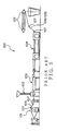
- the electric wire 106 has been manufactured by a wire manufacturing apparatus 100 shown in FIG.5 .
- the wire manufacturing apparatus 100 of FIG.5 has a supply unit 101, a pushing-covering unit 102, a cooling water tank 103, and a winding unit 104.
- the electric wire 106 or a core wire thereof is successively moved through the supply unit 101, the pushing-covering unit 102, the cooling water tank 103, and the winding unit 104.
- the wire manufacturing apparatus 100 has pulleys 107 for moving the core wire 105 or the electric wire 106.
- the supply unit 101 supplies the core wire 105.
- the pushing-covering unit 102 pushes the insulative synthetic resin out so that the covering portion is formed around the core wire 105 supplied from the supply unit 101.
- the cooling water tank 103 cools the covering portion.
- the winding unit 104 cuts off the electric wire 106 in a predetermined length and winds the electric wire 106 around a drum for shipment. Like this, the electric wire 106 is manufactured by the wire manufacturing apparatus 100.
- a connector has a conductive terminal fitting and an insulative connector housing.
- the terminal fitting is attached to an end portion of the electric wire 106 and is electrically-connected with the core wire 105 of the electric wire 106.
- the connector housing is formed in a box-shape and accommodates the terminal fittings.
- the electric wire 106 is firstly cut in a fixed length, and the terminal fitting is attached to the end portion of the electric wire 106.
- the electric wires 106 are connected as the need arises.
- the terminal fitting is inserted into the connector housing.
- the above-described wiring harness is manufactured or assembled.
- the thickness of the core wire 105, material (for example, from viewpoint of heat-resistance) of the covering portion, and service conditions should be distinguished.
- the service conditions mean systems such as an air-bag system, an antilock brake system, a vehicle-speed information system and a power transmission system in which the electric wires 106 are used.
- the electric wires 106 of the wiring harness are variously colored and marked for distinguishing the above systems. Then, in the wire manufacturing apparatus 100 shown in FIG.5 , a colorant is put in the synthetic resin to form the covering portion at the pushing-covering unit 102. The synthetic resin and the colorant are mixed in the pushing-covering unit 102, thereby coloring the synthetic resin with the colorant. The synthetic resin in the same color as that of the colorant is pushed out around the core wire 105. Like this, the covering portion of the electric wire 106 has been colored.
- the motor vehicle is expected to have various kinds of electronic equipment. Consequently, the wiring harness sometimes consists of not less than 100 kinds of the electric wires 106. Therefore, the wire manufacturing apparatus 100 is required to change the color of the covering portion of the electric wire.
- the pushing-covering unit 102 is once stopped in order to change the colorant to be mixed in the synthetic resin.
- the pushing-covering unit 102 has to be frequently stopped, which lowers the producibility of the electric wire 106. Consequently, the cost of the electric wire 106 is enhanced.
- the wire manufacturing apparatus 100 has been sometimes installed for each electric wire 106 having different color, thereby enhancing the cost of the electric wire 106.
- the colorants are required by the same number as that of the colors of the electric wires. Therefore, the trouble to order and stock-control the various kinds of colorants increases, and therefore the man-hour to manufacture the electric wire 106 increases. Further, the cost to convey and store the colorants increases. Therefore, the cost of the electric wire 106 is further enhanced.
- JP 07 065656 A discloses a coating resin color change control mechanism for an electric wire coating extruder. Based on a color change instruction from a control apparatus, a hopper is selected from a plurality of hoppers storing coating resins of different colors and is opened so that the coating resin stored in the selected hopper is supplied to a screw cylinder of a resin extruder. A color sensor is operated to detect the color of the insulator of an electric wire. When the data detected from the color sensor and the color data of the designated color coincide with each other it is detected that the color change is completed.
- DE 21 20 280 A discloses a dye to be applied to extruded plastic material leaving an extruder head, the dye being a mixture of fat or ester soluble colorants together with carriers dissolved in an organic solvent.
- an object of the present invention is to provide a wire coloring method and a wire coloring apparatus, wherein an electric wire in various colors can be easily manufactured, while reducing the cost of the electric wire.
- a wire coloring method according to claim 1 is provided.
- a wire coloring apparatus according to claim 3 is provided.
- a wire coloring method according to claim 5 is provided.
- a wire coloring apparatus according to claim 7 is provided.
- the non-colored electric wire has the covering portion of synthetic resin in which colorant is not put. That is, the covering portion of the non-colored electric wire has a color of synthetic resin itself.
- to color the electric wire means to color the outer surface of the covering portion of the electric wire with a coloring liquid or a paint.
- the coloring liquid the dye is dissolved or dispersed in the solvent.
- the paint the pigment is dispersed in the dispersion liquid. Therefore, when the outer surface of the covering portion is colored by the coloring liquid, the dye soaks into in the covering portion, and when the outer surface of the covering portion is colored by the paint, the pigment adheres to the outer surface without soaking into the covering portion.
- to color the outer surface of the electric wire in the present specification means to dye the outer surface of the covering portion of the electric wire with the dye and also to paint the pigment on the outer surface of the covering portion of the electric wire.
- to color the outer surface of the electric wire in this specification includes to color or dye a colorant-containing ultraviolet curing resin or the like.
- the solvent and the dispersion liquid should have an affinity for synthetic resin forming the covering portion of the electric wire so that the dye securely soaks into the covering portion of the electricwire and the pigment securely adheres to the outer surface of the covering portion of the electric wire.
- the colorant in this specification means the coloring liquid and the paint.
- the wire coloring apparatus 1 ( FIG.1 ) is an apparatus to color an electric wire 3 shown in FIG.2 .
- the electric wires 3 form a wiring harness to be arranged on a motor vehicle.
- the electric wire 3 has a conductive core wire 4 and an insulative covering portion 5 as shown in FIG.2 .
- the core wire 4 is formed by stranding or twisting conductors.
- the conductors forming the core wire 4 are made of conductive metal. Otherwise, the core wire 4 can be a single conductor.
- the covering portion 5 is made of synthetic resin such as polyvinylchloride (PVC) for example.
- PVC polyvinylchloride
- the covering portion 5 covers the core wire 4.
- An outer surface 5a of the covering portion 5 of the electric wire 3 is colored in a specified color Q.
- the electric wire 3 are bundled and connectors are attached to end portions thereof thereby to form the wiring harness.
- the connectors are connected with mating connectors of various electronic equipment of a motor vehicle for transmitting signals or electric powers.
- the wire coloring apparatus 1 colors the outer surface 5a of the non-colored electric wire 3 in a color Q which is different from a color P ( FIG.3A ) of synthetic resin forming the covering portion 5.
- non-colored means a state of synthetic resin to which the colorant is not mixed.
- the non-colored covering portion of the electric wire 3 has the color P of synthetic resin itself.
- to color the electric wire means to color the outer surface 5a of the covering portion 5 of the electric wire 3 with a coloring liquid or a paint.
- the coloring liquid the dye is dissolved or dispersed in the solvent.
- the paint the pigment is dispersed in the dispersion liquid.
- to color the outer surface of the electric wire in the present specification means to dye the outer surface of the covering portion of the electric wire with the dye and also to paint the pigment on the outer surface of the covering portion of the electric wire.
- to color the outer surface of the electric wire in this specification includes to color or dye a colorant-containing ultraviolet curing resin or the like.
- To color the covering portion 5 of the electric wire 3 includes to paint the covering portion 5 of the electric wire 3 and also to dye the covering portion 5 of the electric wire 3.
- the solvent and the dispersion liquid should have an affinity for synthetic resin forming the covering portion of the electric wire so that the dye securely soaks into the covering portion of the electric wire and the pigment securely adheres to the outer surface of the covering portion of the electric wire.
- the colorant means, or includes, the coloring liquid and the paint.
- the wire coloring apparatus 1 has a coloring portion 10 to color the outer surface 5a of the electric wire 3, a colorant-supplying portion 11 to supply the first to fourth colorants B,R,Y,BL (described later), and a control unit 12 as a controlling means, as shown in FIG. 1 .
- the coloring portion 10 has a coloring portion body 21, a pair of rollers 22, a mixing tank 23, sprayers 24 and driers 25.
- the pair of rollers 22 are arranged with an interval with each other so that the electric wire 3 can be moved therebetween in a longitudinal direction of the electric wire 3.
- the left side roller 22(22a) in FIG.1 is positioned upstream of a moving direction of the electric wire3.
- the rightside roller22(22b) in FIG. 1 is positioned downstream of the moving direction of the electric wire 3.
- the mixing tank 23 is formed in a box-shape and attached to the above coloring portion body 21.
- the first to fourth colorants B,R,Y,BL are supplied to the mixing tank 23 from the colorant-supplying portion 11.
- the mixing tank 23 receives the first to fourth colorants B,R, Y,BL and mixes them.
- the mixing tank 23 supplies the mixed colorant to the sprayer 24.
- a pair of sprayers 24 are provided.
- the sprayer 24 sprays the mixed colorant on the electric wire 3 traveling between rollers 22a,22b.
- the sprayers 24 color the outer surface 5a of the electric wire 3 with the paint or with the coloring liquid over the whole periphery of the electric wire 3. That is, the sprayers 24 color the outer surface 5a of the electric wire 3 with the colorant.
- the sprayers 24 color the outer surface 5a in the color Q, which is different from the color P of synthetic resin, over the whole periphery of the electric wire 3.
- the driers 25 are arranged downstream of the sprayers 24 in the moving direction of the electric wire 3.
- the drier 25 dries the paint or the coloring liquid sprayed on the outer surface 5a of the electric wire 3 by the sprayer 24.
- the colorant-supplying portion 11 has a first receiving tank 13 as a first receiving portion, a second receiving tank 14 as a second receiving portion, a third receiving tank 15 as a third receiving portion, a fourth receiving tank 16 as a fourth receiving portion, a first to fourth opening-and-closing valves 17,18,19,20, a first adjusting valve 26 as a first increasing-and-decreasing means, a second adjusting valve 27 as a second increasing-and-decreasing means, a third adjusting valve 28 as a third increasing-and-decreasing means, and a fourth adjusting valve 29 as a fourth increasing-and-decreasing means.
- the first receiving tank 13 is formed in a box-shape and receives the first colorant B of blue.
- the first colorant B is the above-described coloring liquid or the paint. That is, the first colorant B is made up of the solvent B2 and the blue dye B1 dissolved therein, or of the dispersion liquid B2 and the blue pigment B1 dispersed therein.
- the dye and the pigment are shown at the same reference B1, and the solvent and the dispersion liquid are shown at the same reference B2.
- the second receiving tank 14 is formed in a box-shape and receives the second colorant R of red.
- the second colorant R is the above-described coloring liquid or the paint. That is, the second colorant R is made up of the solvent R2 and the red dye R1 dissolved therein, or of the dispersion liquid R2 and the red pigment R1 dispersed therein.
- the dye and the pigment are shown at the same reference R1, and the solvent and the dispersion liquid are shown at the same reference R2.
- the third receiving tank 15 is formed in a box-shape and receives the third colorant Y of yellow.
- the third colorant Y is the above-described coloring liquid or the paint. That is, the third colorant Y is made up of the solvent Y2 and the yellow dye Y1 dissolved therein, or of the dispersion liquid Y2 and the yellow pigment Y1 dispersed therein.
- the dye and the pigment are shown at the same reference Y1
- the solvent and the dispersion liquid are shown at the same reference Y2.
- the fourth receiving tank 16 is formed in a box-shape and receives the fourth colorant BL of black.
- the fourth colorant BL is the above-described coloring liquid or the paint. That is, the fourth colorant BL is made up of the solvent BL2 and the black dye BL1 dissolved therein, or of the dispersion liquid BL2 and the black pigment BL1 dispersed therein.
- the dye and the pigment are shown at the same reference BL1
- the solvent and the dispersion liquid are shown at the same reference BL2.
- the first colorant B of blue in the present specification means that the hue is blue, regardless of the lightness or the chroma (brightness). That is, the first colorant B of blue in the present specification means that the hue is blue, regardless of light blue or dark blue, or bright blue or dim blue.
- the second colorant R of red in the present specification means that the hue is red, regardless of the lightness or the chroma (brightness). That is, the second colorant R of red in the present specification means that the hue is red, regardless of light red or dark red, or bright red or dim red.
- the third colorant Y of yellow in the present specification means that the hue is yellow, regardless of the lightness or the chroma (brightness). That is, the third colorant Y of yellow in the present specification means that the hue is yellow, regardless of light yellow or dark yellow, or bright yellow or dim yellow.
- the fourth colorant BL of black in the present specification means that the hue is black, regardless of the lightness. That is, the fourth colorant BL of black in the present specification means that the hue is black, regardless of light black or dark black.
- the above hue means the tinge or the tint.
- the lightness is the degree of luminosity.
- the chroma is the degree of brightness.
- a piping 30 is connected to the first to fourth receiving tanks 13,14,15,16.
- the piping 30 is also connected to the mixing tank 23.
- the piping 30 leads the first to fourth colorants B,R,Y,BL in the respective first to fourth receiving tanks 13,14,15,16 to the mixing tank 23.
- a non-shown solvent source is connected to the piping 30. This solvent source is connected to the mixing tank 23 through the piping 30.
- the solvent source supplies a solvent, which can remove the colorants B, R,Y,BL of the mixing tank 23, to the mixing tank 23.
- the first to fourth opening-and-closing valves 17,18,19,20 are attached to the piping 30.
- the first opening-and-closing valve 17 When the first opening-and-closing valve 17 is open, the first colorant B in the first receiving tank 13 is supplied to the mixing tank 23.
- the first opening-and-closing valve 17 When the first opening-and-closing valve 17 is closed, the supply of the first colorant B in the first receiving tank 13 to the mixing tank 23 stops.
- the second opening-and-closing valve 18 is open, the second colorant R in the second receiving tank 14 is supplied to the mixing tank 23.
- the second opening-and-closing valve 18 When the second opening-and-closing valve 18 is closed, the supply of the second colorant R in the second receiving tank 14 to the mixing tank 23 stops.
- the third opening-and-closing valve 19 When the third opening-and-closing valve 19 is open, the third colorant Y in the third receiving tank 15 is supplied to the mixing tank 23. When the third opening-and-closing valve 19 is closed, the supply of the third colorant Y in the third receiving tank 23 to the mixing tank 23 stops.
- the fourth opening-and-closing valve 20 When the fourth opening-and-closing valve 20 is open, the fourth colorant BL in the fourth receiving tank 16 is supplied to the mixing tank 23. When the fourth opening-and-closing valve 20 is closed, the supply of the fourth colorant BL in the fourth receiving tank 16 to the mixing tank 23 stops.
- the first to fourth adjusting valves 26,27,28,29 are attached to the piping 30.
- the first adjusting valve 26 increases and decreases a flow rate of the first colorant B from the first receiving tank 13 to the mixing tank 23 by changing its opening ratio.
- the flow rate i.e. the supply rate
- the second adjusting valve 27 increases and decreases a flow rate of the second colorant R from the second receiving tank 14 to the mixing tank 23 by changing its opening ratio.
- the flow rate i.e. the supply rate
- the third adjusting valve 28 increases and decreases a flow rate of the third colorant Y from the third receiving tank 15 to the mixing tank 23 by changing its opening ratio.
- the flow rate i.e. the supply rate
- the fourth adjusting valve 29 increases and decreases a flow rate of the fourth colorant BL from the fourth receiving tank 16 to the mixing tank 23 by changing its opening ratio.
- the flow rate i.e. the supply rate
- the control unit 12 is a computer having well-known RAM, ROM, and CPU.
- the control unit 12 is connected with the first to fourth opening-and-closing valves 17,18,19,20 and the first to fourth adjusting valves 26,27,28,29.
- the control unit 12 controls the opening ratios of the first to fourth adjusting valves 26,27,28,29 in order to increase and decrease the respective colorants B,R,Y,BL supplied to the coloring portion 10.
- the control unit 12 controls the whole wire coloring apparatus 1 by controlling the first to fourth opening-and-closing valves 17,18,19,20 and the first to fourth adjusting valves 26,27,28,29.
- the control unit 12 has data of the mixing ratio of the colorants B,R,Y,BL for each color for the electric wire 3. And also, the control unit 12 has data of the opening ratio of the adjusting valves 26,27,28,29 for each color for the electric wire 3.
- a non-shown input unit and the like are connected to the control unit 12.
- the operation condition of the wire coloring apparatus 1 can be set by the input unit. For example, the length and a specified color of the electric wire 3 are set by the input unit. Further, when the electric wire 3 is colored in a new color, the opening ratios of the respective adjusting valves 26,27,28,29 are given to the control unit 12 from the input unit.
- the operation condition e.g. the length and a specified color of the electric wire 3
- the operation condition e.g. the length and a specified color of the electric wire 3
- the electric wire 3 is set on the roller 22a.
- the wire coloring apparatus 1 is started.
- the rollers 22a,22b rotate, and the electric wire 3 is moved toward the roller 22b from the roller 22a side.
- the control unit opens the first to fourth opening-and-closing valves 17,18,19,20 on demand and controls the opening ratio of the first to fourth adjusting valves 26,27,28,29 according to the specified color of the outer surface 5a of the electric wire 3.
- the first to fourth colorants B,R,Y,BL are mixed in the mixing tank 23, and the mixed colorant is supplied to the sprayer 24.
- the coloring portion 10 of the wire coloring apparatus 1 colors the outer surface 5a (non-colored, i.e. in a color P as shown in FIG.3A ) of the electric wire 3 in the specified color Q over the whole periphery as shown with the hatching in FIGS. 1 and 3B .
- the spray of the mixed colorant from the sprayers is stopped.
- a solvent is firstly supplied to the mixing tank 23 from the solvent source, and the solvent is blown from the sprayers 24 so that the colorants B,R,Y,BL are removed from the mixing tank 23 and the sprayers 24.
- the control unit 12 changes the opening ratios of the adjusting valves 26,27,28,29 in order to change the mixing ratio of the colorants B,R,Y,BL to change the color for the outer surface 5a of the electric wire 3.
- the first colorant B of blue, the second colorant R of red, the third colorant Y of yellow, and the fourth colorant BL of black are mixed in the mixing tank 23.
- the control unit 12 changes the opening ratios of the adjusting valves 26,27,28,29 in order to change the mixing ratio of the colorants B,R,Y,BL.
- the color for the outer surface 5a of the electric wire 3 is changed.
- the outer surface 5a of the electric wire 3 can be colored in every color only by preparing the four colorants B,R,Y, BL. Therefore, the facilities cost for coloring the electric wire 3 can be reduced.
- the color for the outer surface 5a of the electric wire 3 can be easily changed only by changing the mixing ratio of the four colorants B,R,Y,BL. Therefore, the manufacturing efficiency of the electric wire 3 can be improved.
- the outer surface 5a of the electric wire 3 can be colored in every color only by preparing the four colorants B,R,Y,BL, the trouble to order and stock-control the colorants B,R,Y,BL can be reduced, and the cost to convey and store the colorants B,R,Y,BL can be reduced. Therefore, the outer surface 5a of the electric wire 3 can be variously colored easily, and the cost of the electric wire 3 can be reduced.
- the first colorant B of blue, the second colorant R of red, the third colorant Y of yellow, and the fourth colorant BL of black are used.
- a plurality of colorants having respective colors different from each other can be used, not limited to blue, red, yellow, and black.
- the colorants are received in the respective receiving tanks, and the flow rates of the colorants to the mixing tank 23 are adjusted by the increasing-and-decreasing means such as adjusting valves.
- the mixing ratio of the colorants is suitably changed in order to change the color for the outer surface 5a of the electric wire 3.
- a wire coloring method and a wire coloring apparatus are obtained as follows.
- a wire coloring method comprising the steps of: mixing colorants having respective colors different from each other; and coloring an outer surface of a non-colored electric wire, wherein a color for the outer surface of the electric wire is changed by changing a mixing ratio of the colorants.
- a wire coloring apparatus comprising: a coloring portion to color an outer surface of an electric wire; receiving portions to receive respective colorants having respective colors different from each other and to supply the colorants to the coloring portion; a plurality of increasing-and-decreasing means to increase and decrease the respective colorants supplied from the respective receiving portions to the coloring portion; and a controlling means to control the plurality of increasing-and-decreasing means so as to increase and decrease the respective colorants supplied to the coloring portion, wherein the coloring portion mixes the colorants and colors the outer surface of the non-colored electric wire, and the controlling means changes a color for the outer surface of the electric wire by changing a mixing ratio of the colorants.
- the wire coloring apparatus 31 is an apparatus which colors an outer surface 5a of an electric wire 3 in a specified color Q in a manner similar to the wire coloring apparatus 1 of the first embodiment.
- the wire coloring apparatus 31 has a pair of rollers 32, a first coloring unit 33 as a first coloring portion, a second coloring unit 34 as a second coloring portion, a third coloring unit 35 as a third coloring portion, a fourth coloring unit 36 as a fourth coloring portion, and a control unit 50 as a controlling means, as shown in FIG.4 .
- the pair of rollers 32 are arranged with an interval with each other so that the electric wire 3 can be moved therebetween in a longitudinal direction of the electric wire 3.
- the left side roller 32(32a) in FIG.4 is positioned upstream of a moving direction of the electric wire 3.
- the right side roller 32(32b) in FIG.4 is positioned downstream of the moving direction of the electric wire 3.
- the first coloring unit 33 has a coloring unit 37 and a coloring liquid supply portion 38.
- the coloring unit 37 has a unit body 37a, a receiver 37b, sprayers 37c and driers 37d.
- the unit body 37a is arranged between the rollers 32a,32b.
- the unit body 37a is arranged nearer the roller 32a.
- the receiver 37b is formed in a box-shape and attached to the unit body 37a.
- First coloring liquid Ba is supplied from the coloring liquid supply portion 38 to the receiver 37b through a piping 39.
- the receiver 37b receives the first coloring liquid Ba once.
- the receiver 37b supplies the first coloring liquid Ba to the sprayers 37c.
- a pair of sprayers 37c are provided.
- the sprayers 37c are attached to the unit body 37a.
- the sprayer 37c sprays the first coloring liquid Ba on the electric wire 3 traveling between rollers 32a,32b.
- the sprayers 37c dye (color) the outer surface 5a of the electric wire 3 with the first coloring liquid Ba over the whole periphery of the electric wire 3. That is, the sprayers 37c color the outer surface 5a of the electric wire 3 with a colorant.
- the sprayers 37c color the outer surface 5a in a color, which is different from a color P of synthetic resin, over the whole periphery of the electric wire 3.
- the driers 37d are attached to the unit body 37a and arranged downstream of the sprayers 37c in a moving direction of the electric wire 3.
- the drier 37d dries the coloring liquid sprayed on the outer surface 5a of the electric wire 3 by the sprayer 37c.
- the coloring liquid supply portion 38 has a receiving tank 38a, an opening-and-closing valve 38b, and a first adjusting valve 38c as a first increasing-and-decreasing means.
- the receiving tank 38a is formed in a box-shape and receives the first coloring liquid Ba of blue.
- a blue dye Ba1 is dissolved or dispersed in a solvent Ba2.
- the first coloring liquid Ba of blue in the present specification means that the hue is blue, regardless of the lightness or the chroma (brightness). That is, the first coloring liquid Ba of blue in the present specification means that the hue is blue, regardless of light blue or dark blue, or bright blue or dim blue.
- the above hue means the tinge or the tint.
- the lightness is the degree of luminosity.
- the chroma is the degree of brightness.
- the piping 39 is connected with the receiving tank 38a.
- the piping 39 is connected to the receiver 37b of the first coloring unit 33.
- the piping 39 leads the first coloring liquid Ba in the receiving tank 38a to the receiver 37b.
- the opening-and-closing valve 38b is attached to the piping 39. When the opening-and-closing valve 38b is open, the first coloring liquid Ba in the receiving tank 38a is supplied to the receiver 37b. When the opening-and-closing valve 38b is closed, the supply of the first coloring liquid Ba in the receiving tank 38a to the receiver 37b stops.
- the first adjusting valve 38c is attached to the piping 39.
- the first adjusting valve 38c increases and decreases a flow rate of the first coloring liquid Ba from the receiving tank 38a to the receiver 37b by changing its opening ratio. That is, the first adjusting valve 38c increases and decreases the flow rate of the first coloring liquid Ba with which the first coloring unit 33 dyes the outer surface 5a of the electric wire 3.
- the flow rate i.e. the supply rate
- the first coloring unit 33 dyes the outer surface 5a of the electric wire 3 with the first coloring liquid Ba.
- the second coloring unit 34 has a coloring unit 40 and a coloring liquid supply portion 41.
- the coloring unit 40 has a unit body 40a, a receiver 40b, sprayers 40c and driers 40d.
- the unit body 40a is arranged between the rollers 32a,32b.
- the unit body 40a is arranged next to the unit body 37a.
- the receiver 40b is formed in a box-shape and attached to the unit body 40a.
- Second coloring liquid Ra is supplied from the coloring liquid supply portion 41 to the receiver 40b through a piping 42.
- the receiver 40b receives the second coloring liquid Ra once.
- the receiver 40b supplies the second coloring liquid Ra to the sprayers 40c.
- a pair of sprayers 40c are provided.
- the sprayers 40c are attached to the unit body 40a.
- the sprayer 40c sprays the second coloring liquid Ra on the electric wire 3 traveling between rollers 32a,32b.
- the sprayers 40c dye (color) the outer surface 5a of the electric wire 3 with the second coloring liquid Ra over the whole periphery of the electric wire 3. That is, the sprayers 40c color the outer surface 5a of the electric wire 3 with a colorant.
- the sprayers 40c color the outer surface 5a in a color, which is different from a color P of synthetic resin, over the whole periphery of the electric wire 3.
- the driers 40d are attached to the unit body 40a and arranged downstream of the sprayers 40c in the moving direction of the electric wire 3.
- the drier 40d dries the coloring liquid sprayed on the outer surface 5a of the electric wire 3 by the sprayer 40c.
- the coloring liquid supply portion 41 has a receiving tank 41 a, an opening-and-closing valve 41 b, and a second adjusting valve 41c as a second increasing-and-decreasing means.
- the receiving tank 41a is formed in a box-shape and receives the second coloring liquid Ra of red.
- a red dye Ra1 is dissolved or dispersed in a solvent Ra2.
- the second coloring liquid Ra of red in the present specification means that the hue is red, regardless of the lightness or the chroma (brightness). That is, the second coloring liquid Ra of red in the present specification means that the hue is red, regardless of light red or dark red, or bright red or dim red.
- the piping 42 is connected with the receiving tank 41 a.
- the piping 42 is connected to the receiver 40b of the second coloring unit 34.
- the piping 42 leads the second coloring liquid Ra in the receiving tank 41 a to the receiver 40b.
- the opening-and-closing valve 41 b is attached to the piping 42. When the opening-and-closing valve 41 b is open, the second coloring liquid Ra in the receiving tank 41 a is supplied to the receiver 40b. When the opening-and-closing valve 41 b is closed, the supply of the second coloring liquid Ra in the receiving tank 41a to the receiver 40b stops.
- the second adjusting valve 41c is attached to the piping 42.
- the second adjusting valve 41 c increases and decreases a flow rate of the second coloring liquid Ra from the receiving tank 41a to the receiver 40b by changing its opening ratio. That is, the second adjusting valve 41 c increases and decreases the flow rate of the second coloring liquid Ra with which the second coloring unit 34 dyes the outer surface 5a of the electric wire 3.
- the flow rate i.e. the supply rate
- the second coloring unit 34 dyes the outer surface 5a of the electric wire 3 with the second coloring liquid Ra.
- the third coloring unit 35 has a coloring unit 43 and a coloring liquid supply portion 44.
- the coloring unit 43 has a unit body 43a, a receiver 43b, sprayers 43c and driers 43d.
- the unit body 43a is arranged between the rollers 32a,32b.
- the unit body 43a is arranged next to the unit body 40a.
- the receiver 43b is formed in a box-shape and attached to the unit body 43a.
- Third coloring liquid Ya is supplied from the coloring liquid supply portion 44 to the receiver 43b through a piping 45.
- the receiver 43b receives the third coloring liquid Ya once.
- the receiver 43b supplies the third coloring liquid Ya to the sprayers 43c.
- a pair of sprayers 43c are provided.
- the sprayers 43c are attached to the unit body 43a.
- the sprayer 43c sprays the third coloring liquid Ya on the electric wire 3 traveling between rollers 32a,32b.
- the sprayers 43c dye (color) the outer surface 5a of the electric wire 3 with the third coloring liquid Ya over the whole periphery of the electric wire 3. That is, the sprayers 43c color the outer surface 5a of the electric wire 3 with a colorant.
- the sprayers 43c color the outer surface 5a in a color, which is different from a color P of synthetic resin, over the whole periphery of the electric wire 3.
- the driers 43d are attached to the unit body 43a and arranged downstream of the sprayers 43c in the moving direction of the electric wire 3.
- the drier 43d dries the coloring liquid sprayed on the outer surface 5a of the electric wire 3 by the sprayer 43c.
- the coloring liquid supply portion 44 has a receiving tank 44a, an opening-and-closing valve 44b, and a third adjusting valve 44c as a third increasing-and-decreasing means.
- the receiving tank 44a is formed in a box-shape and receives the third coloring liquid Ya of yellow.
- a yellow dye Ya1 is dissolved or dispersed in a solvent Ya2.
- the third coloring liquid Ya of yellow in the present specification means that the hue is yellow, regardless of the lightness or the chroma (brightness). That is, the third coloring liquid Ya of yellow in the present specification means that the hue is yellow, regardless of light yellow or dark yellow, or bright yellow or dim yellow.
- the piping 45 is connected with the receiving tank 44a.
- the piping 45 is connected to the receiver 43b.
- the piping 45 leads the third coloring liquid Ya in the receiving tank 44a to the receiver 43b.
- the opening-and-closing valve 44b is attached to the piping 45. When the opening-and-closing valve 44b is open, the third coloring liquid Ya in the receiving tank 44a is supplied to the receiver 43b. When the opening-and-closing valve 44b is closed, the supply of the third coloring liquid Ya in the receiving tank 44a to the receiver 43b stops.
- the third adjusting valve 44c is attached to the piping 45.
- the third adjusting valve 44c increases and decreases a flow rate of the third coloring liquid Ya from the receiving tank 44a to the receiver 43b by changing its opening ratio. That is, the third adjusting valve 44c increases and decreases the flow rate of the third coloring liquid Ya with which the third coloring unit 35 dyes the outer surface 5a of the electric wire 3.
- the flow rate i.e. the supply rate
- the third coloring unit 35 dyes the outer surface 5a of the electric wire 3 with the third coloring liquid Ya.
- the fourth coloring unit 36 has a coloring unit 46 and a coloring liquid supply portion 47.
- the coloring unit 46 has a unit body 46a, a receiver 46b, sprayers 46c and driers 46d.
- the unit body 46a is arranged between the rollers 32a,32b.
- the unit body 46a is arranged next to the unit body 43a and near the roller 32b.
- the first to fourth coloring units 33,34,35,36 are lined up along the electric wire 3 from the upstream side to the downstream side thereof.
- the receiver 46b is formed in a box-shape and attached to the unit body 46a.
- Fourth coloring liquid BLa is supplied from the coloring liquid supply portion 47 to the receiver 46b through a piping 48.
- the receiver 46b receives the fourth coloring liquid BLa once.
- the receiver 46b supplies the fourth coloring liquid BLa to the sprayers 46c.
- a pair of sprayers 46c are provided.
- the sprayers 46c are attached to the unit body 46a.
- the sprayer 46c sprays the fourth coloring liquid BLa on the electric wire 3 traveling between rollers 32a,32b.
- the sprayers 46c dye (color) the outer surface 5a of the electric wire 3 with the fourth coloring liquid BLa over the whole periphery of the electric wire 3. That is, the sprayers 46c color the outer surface 5a of the electric wire 3 with a colorant.
- the sprayers 46c color the outer surface 5a in a color Q, which is different from a color P of synthetic resin, over the whole periphery of the electric wire 3.
- the driers 46d are attached to the unit body 46a and arranged downstream of the sprayers 46c in the moving direction of the electric wire 3.
- the drier 46d dries the coloring liquid sprayed on the outer surface 5a of the electric wire 3 by the sprayer 46c.
- the coloring liquid supply portion 47 has a receiving tank 47a, an opening-and-closing valve 47b, and a fourth adjusting valve 47c as a fourth increasing-and-decreasing means.
- the receiving tank 47a is formed in a box-shape and receives the fourth coloring liquid BLa of black.
- a black dye BLa1 is dissolved or dispersed in a solvent BLa2.
- the fourth coloring liquid BLa of black in the present specification means that the hue is black, regardless of the lightness. That is, the fourth coloring liquid BLa of black in the present specification means that the hue is black, regardless of light black or dark black.
- the piping 48 is connected with the receiving tank 47a.
- the piping 48 is connected to the receiver 46b.
- the piping 48 leads the fourth coloring liquid BLa in the receiving tank 47a to the receiver 46b.
- the opening-and-closing valve 47b is attached to the piping 48. When the opening-and-closing valve 47b is open, the fourth coloring liquid BLa in the receiving tank 47a is supplied to the receiver 46b. When the opening-and-closing valve 47b is closed, the supply of the fourth coloring liquid BLa in the receiving tank 47a to the receiver 46b stops.
- the fourth adjusting valve 47c is attached to the piping 48.
- the fourth adjusting valve 47c increases and decreases a flow rate of the fourth coloring liquid BLa from the receiving tank 47a to the receiver 46b by changing its opening ratio. That is, the fourth adjusting valve 47c increases and decreases the flow rate of the fourth coloring liquid BLa with which the fourth coloring unit 36 dyes the outer surface 5a of the electric wire 3.
- the flow rate i.e. the supply rate
- the fourth coloring unit 36 dyes the outer surface 5a of the electric wire 3 with the fourth coloring liquid BLa.
- the control unit 50 is a computer having well-known RAM, ROM, and CPU.
- the control unit 50 is connected with the first to fourth opening-and-closing valves 38b,41 b,44b,47b and the first to fourth adjusting valves 38c,41 c,44c,47c.
- the control unit 50 controls the opening ratios of the first to fourth adjusting valves 38c, 41 c,44c,47c in order to increase and decrease the respective coloring liquids Ba,Ra,Ya,BLa supplied to the respective receivers 37b,40b,43b,46b.
- the control unit 50 controls the whole wire coloring apparatus 31 by controlling the first to fourth opening-and-closing valves 38b,41 b,44b,47b and the first to fourth adjusting valves 38c,41 c,44c,47c.
- the control unit 50 has data of the amount of the coloring liquids Ba,Ra,Ya,BLa for each color for the electric wire 3. And also, the control unit 50 has data of the opening ratio of the adjusting valves 38c,41c,44c, 47c for each color for the electric wire 3.
- a non-shown input unit and the like are connected to the control unit 50.
- the operation condition of the wire coloring apparatus 31 can be set by the input unit. For example, the length and a specified color of the electric wire 3 are set by the input unit. Further, when the electric wire 3 is colored in a new coior, the opening ratios of the respective adjusting valves 38c,41c,44c, 47c are given to the control unit 50 from the input unit.
- the operation condition (e. g. the length and a specified color of the electric wire 3) is firstly set by the input unit.
- the electric wire 3 is set on the roller 32a.
- the wire coloring apparatus 31 is started.
- the rollers 32a,32b rotate, and the electric wire 3 is moved toward the roller 32b from the roller 32a side.
- the control unit opens the first to fourth opening-and-closing valves 38b,41b,44b,47b on demand and controls the opening ratio of the first to fourth adjusting valves 38c,41 c,44c,47c according to the specified color of the outer surface 5a of the electric wire 3.
- the outer surface 5a of the electric wire 3 is firstly dyed (colored) by the first coloring unit 33. That is, the first coloring unit 33 dyes the non-colored outer surface 5a (color P) of the electric wire 3 in blue B ( FIG.4 ).
- the second coloring unit 34 dyes the outer surface 5a (of color B) of the electric wire 3 with the second coloring liquid Ra of red in a color BR ( FIG. 4 ).
- the third coloring unit 35 dyes the outer surface 5a (of color BR) of the electric wire 3 with the third coloring liquid Ya of yellow in a color BRY ( FIG.4 ).
- the fourth coloring unit 36 dyes the outer surface 5a (of color BRY) of the electric wire 3 with the fourth coloring liquid BLa of black in the specified color Q ( FIG.4 ).
- the outer surface 5a of the electric wire 3 is dyed (colored) in turn, or successively, with the first coloring liquid Ba of blue, the second coloring liquid Ra of red, the third coloring liquid Ya of yellow, and the fourth coloring liquid BLa of black, while moving the electric wire 3.
- the color of the outer surface 5a of the electric wire 3 is changed by increasing and decreasing the amount of each of the coloring liquids Ba,Ra,Ya, BLa.
- the outer surface 5a of the electric wire 3 can be colored in every color only by preparing the four coloring liquids Ba, Ra, Ya, BLa. Therefore, the facilities cost for coloring the electric wire 3 can be reduced.
- the color for the outer surface 5a of the electric wire 3 can be easily changed only by changing the amount of each of the four coloring liquids B,R,Y,BL. Therefore, the manufacturing efficiency of the electric wire 3 can be improved.
- the outer surface 5a of the electric wire 3 can be colored in every color only by preparing the four coloring liquids Ba,Ra,Ya,BLa, the trouble to order and stock-control the coloring liquids Ba, Ra, Ya,BLa can be reduced, and the cost to convey and store the coloring liquids Ba,Ra,Ya,BLa can be reduced. Therefore, the outer surface 5a of the electric wire 3 can be variously colored easily, and the cost of the electric wire 3 can be reduced.
- the outer surface 5a of the electric wire 3 is dyed (colored) in turn with the first to fourth coloring liquids Ba,Ra,Ya,BLa. That is, it is not necessary to dye (color) the electric wire 3 in the specified color Q at a time. Therefore, the electric wire 3 can be dyed (colored) in the specified color Q by dying it with the coloring liquids Ba,Ra,Ya,BLa one by one with a time interval of, for example, several hours or several days. Therefore, limitation of the process for coloring the electric wire 3 can be relaxed, thereby increasing the degree of freedom of the coloring process.
- the first to fourth coloring units 33,34,35,36 are lined up along the moving direction of the electric wire 3. Therefore, the outer surface 5a of the electric wire 3 can be securely dyed successively with the first coloring liquid Ba of blue, the second coloring liquid Ra of red, the third coloring liquid Ya of yellow, and the fourth coloring liquid BLa of black. Therefore, the outer surface 5a of the electric wire 3 can be securely colored in every color.
- the first coloring liquid Ba of blue, the second coloring liquid Ra of red, the third coloring liquid Ya of yellow, and the fourth coloring liquid BLa of black are used.
- a plurality of coloring liquids having respective colors different from each other can be used, not limited to blue, red, yellow, and black.
- the coloring liquids are received in the respective receiving tanks, and the flow rates of the coloring liquids to the receivers are adjusted by the increasing-and-decreasing means such as adjusting valves.
- the amount of each coloring liquid is suitably changed in order to change the color for the outer surface 5a of the electric wire 3.
- a wire coloring method comprising the step of: coloring an outer surface of a non-colored electric wire by dyeing the outer surface of the electric wire in turn with coloring liquids having respective colors different from each other, wherein a color for the outer surface of the electric wire is changed by increasing and decreasing each of the coloring liquids.
- a wire coloring apparatus comprising: coloring portions to dye an outer surface of an electric wire with respective coloring liquids having respective colors different from each other; a plurality of increasing-and-decreasing means to increase and decrease the respective coloring liquids, to dye the outer surface of the electric wire, to the respective coloring portions; and a controlling means to control the plurality of increasing-and-decreasing means so as to increase and decrease the respective coloring liquids to the respective coloring portions, wherein an outer surface of a non-colored electric wire is colored by dyeing the outer surface of the electric wire in turn with the coloring liquids having respective colors different from each other, and a color for the outer surface of the electric wire is changed by increasing and decreasing each of the coloring liquids by the controlling means.
- the above-described embodiment is for the electric wire 3 forming the wiring harness arranged on a motor vehicle.
- the electric wire 3 manufactured by the inventive manufacturing method is not limited to a vehicle use and can be used for electronic equipment such as a portable computer and for various electric machines.
- various wire coloring means such as dipping, atomization, injection, printing, and transcription may be used.
- the coloring liquid or the paint such as acrylic paint, ink (dye series and pigment series), and the like may be used.
Landscapes
- Engineering & Computer Science (AREA)
- Manufacturing & Machinery (AREA)
- Manufacturing Of Electric Cables (AREA)
- Processes Specially Adapted For Manufacturing Cables (AREA)
Claims (9)
- Procédé de coloration de fil comprenant les étapes consistant à :fournir des colorants (B, R, Y, BL) qui présentent des couleurs différentes les unes des autres ;fournir les colorants (B, R, Y, BL) à une partie coloration (10) par l'intermédiaire de moyens d'augmentation et de diminution respectifs (26 à 29) capables d'augmenter et de diminuer le colorant respectif (B, R, Y, BL) fourni à la partie coloration (10) par une partie réception respective (13 à 16) ;mélanger les colorants (B, R, Y, BL) fournis à la partie coloration (10) ; etcolorer une surface extérieure (5a) d'un fil électrique non coloré (3) à l'aide des colorants mélangés (B, R, Y, BL) ;dans lequel le rapport d'ouverture des moyens d'augmentation et de diminution respectifs (26 à 29) est commandé selon une couleur spécifiée de la surface extérieure (5a) du fil électrique (3) ;et dans lequel la couleur de la surface extérieure (5a) du fil électrique (3) est modifiée en modifiant le rapport de mélange des colorants (B, R, Y, BL) en modifiant par conséquent le rapport d'ouverture des moyens d'augmentation et de diminution respectifs (26 à 29).
- Procédé de coloration de fil selon la revendication 1, dans lequel un premier colorant bleu (B), un deuxième colorant rouge (R), un troisième colorant jaune (Y) et un quatrième colorant noir (BL) sont utilisés.
- Appareil de coloration de fil (1) comprenant :une partie coloration (10) destinée à colorer une surface extérieure (5a) d'un fil électrique (3) ;des parties réceptions (13 à 16) destinées à recevoir un colorant respectif (B, R, Y, BL), les colorants (B, R, Y, BL) présentant des couleurs respectives différentes les unes des autres, et à fournir le colorant respectif (B, R, Y, BL) à la partie coloration (10) ;une pluralité de moyens d'augmentation et de diminution (26 à 29) destinés à augmenter et à diminuer le colorant respectif (B, R, Y, BL) fourni à la partie coloration (10) par la partie réception respective (13 à 16) ;dans lequel la partie coloration (10) comprend un réservoir de mélange (23) destiné à mélanger les colorants (B, R, Y, BL) fournis à la partie coloration (10) par les parties réceptions (13 à 16) ; etdes moyens de commande (12) adaptés pour commander la pluralité de moyens d'augmentation et de diminution (26 à 29), afin d'augmenter et diminuer le colorant respectif (B, R, Y, BL) fourni à la partie coloration (10) ;dans lequel les moyens de commande sont adaptés pour commander le rapport d'ouverture des moyens d'augmentation et de diminution respectifs (26 à 29) selon une couleur spécifiée de la surface extérieure (5a) du fil électrique (3), et pour modifier la couleur de la surface extérieure (5a) du fil électrique (3) en modifiant le rapport de mélange des colorants (B, R, Y, BL) en modifient le rapport d'ouverture des moyens d'augmentation et de diminution respectifs (26 à 29).
- Appareil de coloration de fil selon la revendication 3, dans lequel les parties réceptions (13 à 16) comprennent :une première partie réception (13) destinée à recevoir un premier colorant bleu (B) et à fournir le premier colorant (B) à la partie coloration (10) ;une deuxième partie réception (14) destinée à recevoir un deuxième colorant rouge (R) et à fournir le deuxième colorant (R) à la partie coloration (10) ;une troisième partie réception (15) destinée à recevoir un troisième colorant jaune (Y) et à fournir le troisième colorant (Y) à la partie coloration (10) ; etune quatrième partie réception (16) destinée à recevoir un quatrième colorant noir (BL) et à fournir le quatrième colorant (BL) à la partie coloration (10) ;et dans lequel la pluralité de moyens d'augmentation et de diminution (26 à 29) comprennent :des premiers moyens d'augmentation et de diminution (26) destinés à augmenter et à diminuer le premier colorant (B) fourni à la partie coloration (10) par la première partie réception (13) ;des deuxièmes moyens d'augmentation et de diminution (27) destinés à augmenter et à diminuer le deuxième colorant (R) fourni à la partie coloration (10) par la deuxième partie réception (14) ;des troisièmes moyens d'augmentation et de diminution (28) destinés à augmenter et à diminuer le troisième colorant (Y) fourni à la partie coloration (10) par la troisième partie réception (15) ; etdes quatrièmes moyens d'augmentation et de diminution (29) destinés à augmenter et à diminuer le quatrième colorant (BL) fourni à la partie coloration (10) par la quatrième partie réception (16).
- Procédé de coloration de fil comprenant les étapes consistant à :fournir des liquides colorants (Ba, Ra, Ya, BLa) qui présentent des couleurs différentes les unes des autres ;fournir le liquide colorant respectif (Ba, Ra, Ya, BLa) à une unité coloration respective (37, 40, 43, 46) par l'intermédiaire de moyens d'augmentation et de diminution respectifs (38c, 41c, 44c, 47c) capables d'augmenter et de diminuer le liquide colorant respectif (Ba, Ra, Ya, BLa) fourni à l'unité coloration respective (37, 40, 43, 46) ; etcolorer une surface extérieure (5a) d'un fil électrique non coloré (3) en colorant la surface extérieure (5a) du fil électrique (3) tour à tour avec le liquide colorant respectif (Ba, Ra, Ya, BLa) dans l'unité coloration respective (37, 40, 43, 46) ;dans lequel le rapport d'ouverture des moyens d'augmentation et de diminution respectifs (38c, 41c, 44c, 47c) est commandé selon une couleur spécifiée de la surface extérieure (5a) du fil électrique (3) ;et dans lequel la couleur de la surface extérieure (5a) du fil électrique (3) est modifiée en augmentant et en diminuant la quantité de liquide colorant respectif (Ba, Ra, Ya, BLa) fourni à l'unité coloration respective (37, 40, 43, 46).
- Procédé de coloration de fil selon la revendication 5, dans lequel un premier liquide colorant bleu (Ba), un deuxième liquide colorant rouge (Ra), un troisième liquide colorant jaune (Ya) et un quatrième liquide colorant noir (BLa) sont utilisés.
- Appareil de coloration de fil (31) comprenant :des parties colorations (33 à 36) agencées de façon à colorer une surface extérieure (5a) d'un fil électrique (3) tour à tour avec un liquide colorant respectif (Ba, Ra, Ya, BLa), les liquides colorants (Ba, Ra, Ya, BLa) présentant des couleurs respectives différentes les unes des autres ;les parties colorations (33 à 36) comprenant respectivement une unité coloration (37, 40, 43, 46) et une partie fourniture de liquide colorant (38, 41, 44, 47) ;dans lequel la partie fourniture de liquide colorant respective (38, 41, 44, 47) comprend des moyens d'augmentation et de diminution (38c, 41c, 44c, 47c) destinés à augmenter et à diminuer le liquide colorant respectif (Ba, Ra, Ya, BLa), afin de colorer la surface extérieure (5a) du fil électrique (3), fourni à l'unité coloration respective (37, 40, 43, 46) ; etdes moyens de commandes (50) adaptés pour commander la pluralité de moyens d'augmentation et de diminution (38c, 41c, 44c, 47c), afin d'augmenter et diminuer le liquide colorant respectif (Ba, Ra, Ya, BLa) fourni à l'unité coloration respective (37, 40, 43, 46), dans lequel les moyens de commande (50) sont adaptés de façon à commander le rapport d'ouverture des moyens d'augmentation et de diminution respectifs (38c, 41c, 44c, 47c) selon une couleur spécifiée de la surface extérieure (5a) du fil électrique (3) et à modifier la couleur de la surface extérieure (5a) du fil électrique (3) en augmentant et en diminuant la quantité de liquide colorant respectif (Ba, Ra, Ya, BLa) fourni à l'unité coloration respective (37, 40, 43, 46).
- Appareil de coloration de fil (31) selon la revendication 7, dans lequel les parties colorations (33 à 36) comprennent :une première partie coloration (33) destinée à colorer la surface extérieure (5a) du fil électrique (3) avec un premier liquide colorant bleu (Ba) ;une deuxième partie coloration (34) destinée à colorer la surface extérieure (5a) du fil électrique (3) avec un deuxième liquide colorant rouge (Ra) ;une troisième partie coloration (35) destinée à colorer la surface extérieure (5a) du fil électrique (3) avec un troisième liquide colorant jaune (Ya);une quatrième partie coloration (36) destinée à colorer la surface extérieure (5a) du fil électrique (3) avec un quatrième liquide colorant noir (BLa) ;et dans lequel les moyens d'augmentation et de diminution (38c, 41c, 44c, 47c) comprennent :des premiers moyens d'augmentation et de diminution (38c) destinés à augmenter et à diminuer le premier liquide colorant (Ba), afin de colorer la surface extérieure (5a) du fil électrique (3), fourni à la première unité coloration (37);des deuxièmes moyens d'augmentation et de diminution (41c) destinés à augmenter et à diminuer le deuxième liquide colorant (Ra), afin de colorer la surface extérieure (5a) du fil électrique (3), fourni à la deuxième unité coloration (40) ;des troisièmes moyens d'augmentation et de diminution (44c) destinés à augmenter et à diminuer le troisième liquide colorant (Ya), afin de colorer la surface extérieure (5a) du fil électrique (3), fourni à la troisième unité coloration (43) ;des quatrièmes moyens d'augmentation et de diminution (47c) destinés à augmenter et à diminuer le quatrième liquide colorant (BLa), afin de colorer la surface extérieure (5a) du fil électrique (3), fourni à la quatrième unité coloration (46).
- Appareil de coloration de fil (31) selon la revendication 8, dans lequel le fil électrique (3) est déplacé dans sa direction longitudinale, les quatre parties colorations (33 à 36) sont agencées dans la direction de déplacement du fil électrique (3), et les parties colorations (33 à 36) colorent la surface extérieure (5a) du fil électrique (3) et se déplacent tour à tour.
Applications Claiming Priority (2)
| Application Number | Priority Date | Filing Date | Title |
|---|---|---|---|
| JP2001400642A JP4263404B2 (ja) | 2001-12-28 | 2001-12-28 | 電線の着色方法 |
| JP2001400642 | 2001-12-28 |
Publications (3)
| Publication Number | Publication Date |
|---|---|
| EP1324355A2 EP1324355A2 (fr) | 2003-07-02 |
| EP1324355A3 EP1324355A3 (fr) | 2003-12-03 |
| EP1324355B1 true EP1324355B1 (fr) | 2012-05-09 |
Family
ID=19189646
Family Applications (1)
| Application Number | Title | Priority Date | Filing Date |
|---|---|---|---|
| EP02023686A Expired - Lifetime EP1324355B1 (fr) | 2001-12-28 | 2002-10-22 | Méthode de coloration de fils et appareil de coloration de fils |
Country Status (3)
| Country | Link |
|---|---|
| US (1) | US20030124253A1 (fr) |
| EP (1) | EP1324355B1 (fr) |
| JP (1) | JP4263404B2 (fr) |
Families Citing this family (8)
| Publication number | Priority date | Publication date | Assignee | Title |
|---|---|---|---|---|
| JP3971269B2 (ja) * | 2002-08-09 | 2007-09-05 | 矢崎総業株式会社 | 電線のコーティング方法及び装置 |
| JP4452036B2 (ja) * | 2003-06-24 | 2010-04-21 | 矢崎総業株式会社 | 電線の着色装置 |
| US7320553B1 (en) | 2005-11-03 | 2008-01-22 | Efrem Nunez | Electrical wire marker |
| JP5060761B2 (ja) * | 2006-10-16 | 2012-10-31 | 矢崎総業株式会社 | 着色ノズル及びその着色ノズルを有した着色ユニット |
| JP5997427B2 (ja) * | 2011-09-20 | 2016-09-28 | 矢崎エナジーシステム株式会社 | 耐候性電線 |
| WO2017193031A1 (fr) | 2016-05-06 | 2017-11-09 | RADCO Infusion Technologies, LLC | Infusion de substrat linéaire continue |
| US9718080B1 (en) | 2016-05-06 | 2017-08-01 | RADCO Infusion Technologies, LLC | Linear substrate infusion compartment |
| CN107618271B (zh) * | 2017-09-28 | 2019-04-09 | 江苏永鼎股份有限公司 | 一种表面印字装置 |
Family Cites Families (8)
| Publication number | Priority date | Publication date | Assignee | Title |
|---|---|---|---|---|
| US2981225A (en) * | 1959-01-22 | 1961-04-25 | Gamewell Co | Wire insulation coloring apparatus |
| DE2120280A1 (en) | 1970-12-03 | 1972-06-15 | Thaelmann Schwermaschbau Veb | Colouring extruded plastic - by dyestuff in an organic softening soln |
| US4376512A (en) * | 1980-11-20 | 1983-03-15 | Kenneth Kistner | Coating system |
| US4397422A (en) * | 1981-06-04 | 1983-08-09 | Gwyn Marion V | Full spectrum selective color producing and spraying device |
| US4457258A (en) * | 1983-01-04 | 1984-07-03 | Cocks Eric H | Marking apparatus for paints and inks |
| US4877645A (en) * | 1988-02-26 | 1989-10-31 | American Telephone & Telegraph At&T Technologies, Inc. | Methods of and apparatus for applying a coating material to elongated material |
| DE3942483A1 (de) * | 1989-12-22 | 1991-06-27 | Kabelmetal Electro Gmbh | Verfahren zur fortlaufenden kennzeichnung von langgestrecktem gut |
| JPH0765656A (ja) | 1993-08-25 | 1995-03-10 | Yazaki Corp | 電線被覆押出機の被覆樹脂色替え制御機構 |
-
2001
- 2001-12-28 JP JP2001400642A patent/JP4263404B2/ja not_active Expired - Fee Related
-
2002
- 2002-10-22 EP EP02023686A patent/EP1324355B1/fr not_active Expired - Lifetime
- 2002-10-28 US US10/281,258 patent/US20030124253A1/en not_active Abandoned
Also Published As
| Publication number | Publication date |
|---|---|
| EP1324355A3 (fr) | 2003-12-03 |
| JP4263404B2 (ja) | 2009-05-13 |
| JP2003203530A (ja) | 2003-07-18 |
| EP1324355A2 (fr) | 2003-07-02 |
| US20030124253A1 (en) | 2003-07-03 |
Similar Documents
| Publication | Publication Date | Title |
|---|---|---|
| US7875309B2 (en) | Method for coating electrical cable | |
| EP1324355B1 (fr) | Méthode de coloration de fils et appareil de coloration de fils | |
| US8017177B2 (en) | Method of automatically marking article and automatic marking device | |
| EP1441368B1 (fr) | Procede de fabrication de cable et appareil de fabrication de cable | |
| JP2008103191A (ja) | シールド電線及びシールド電線の識別方法 | |
| US7482539B2 (en) | Electric wire | |
| MXPA05004904A (es) | Alojamiento de conector electrico, un metodo para marcar el alojamiento de conector electrico y un metodo para insertar una terminal de metal en el alojamiento de conector electrico. | |
| US7504586B2 (en) | Cable and cable identificating method | |
| US20060118325A1 (en) | Electric wire and wire harness | |
| JP3887345B2 (ja) | 電線の着色装置及び電線の着色方法 | |
| EP1768134B1 (fr) | Dispositif de coloration de cable electrique et dispositif d'usinage de cable electrique | |
| US20060110527A1 (en) | Method and device for marking wire | |
| JP4611605B2 (ja) | 電線、ワイヤハーネスの受注生産方法及びこれらの受注生産システム | |
| US7361840B2 (en) | Wire recycling method | |
| US20040265485A1 (en) | Method and apparatus for coloring electric wire | |
| MXPA04008098A (es) | Cable electrico y aparato para colorear cable electrico. | |
| WO2004061869A1 (fr) | Procede de coloration d'un fil electrique |
Legal Events
| Date | Code | Title | Description |
|---|---|---|---|
| PUAI | Public reference made under article 153(3) epc to a published international application that has entered the european phase |
Free format text: ORIGINAL CODE: 0009012 |
|
| AK | Designated contracting states |
Designated state(s): AT BE BG CH CY CZ DE DK EE ES FI FR GB GR IE IT LI LU MC NL PT SE SK TR |
|
| AX | Request for extension of the european patent |
Extension state: AL LT LV MK RO SI |
|
| PUAL | Search report despatched |
Free format text: ORIGINAL CODE: 0009013 |
|
| AK | Designated contracting states |
Kind code of ref document: A3 Designated state(s): AT BE BG CH CY CZ DE DK EE ES FI FR GB GR IE IT LI LU MC NL PT SE SK TR |
|
| AX | Request for extension of the european patent |
Extension state: AL LT LV MK RO SI |
|
| 17P | Request for examination filed |
Effective date: 20040310 |
|
| AKX | Designation fees paid |
Designated state(s): AT BE BG |
|
| REG | Reference to a national code |
Ref country code: DE Ref legal event code: 8566 |
|
| RBV | Designated contracting states (corrected) |
Designated state(s): DE FR GB |
|
| RAP1 | Party data changed (applicant data changed or rights of an application transferred) |
Owner name: YAZAKI CORPORATION |
|
| 17Q | First examination report despatched |
Effective date: 20100205 |
|
| GRAP | Despatch of communication of intention to grant a patent |
Free format text: ORIGINAL CODE: EPIDOSNIGR1 |
|
| GRAS | Grant fee paid |
Free format text: ORIGINAL CODE: EPIDOSNIGR3 |
|
| GRAA | (expected) grant |
Free format text: ORIGINAL CODE: 0009210 |
|
| AK | Designated contracting states |
Kind code of ref document: B1 Designated state(s): DE FR GB |
|
| REG | Reference to a national code |
Ref country code: GB Ref legal event code: FG4D |
|
| REG | Reference to a national code |
Ref country code: DE Ref legal event code: R096 Ref document number: 60242849 Country of ref document: DE Effective date: 20120712 |
|
| PLBE | No opposition filed within time limit |
Free format text: ORIGINAL CODE: 0009261 |
|
| STAA | Information on the status of an ep patent application or granted ep patent |
Free format text: STATUS: NO OPPOSITION FILED WITHIN TIME LIMIT |
|
| 26N | No opposition filed |
Effective date: 20130212 |
|
| REG | Reference to a national code |
Ref country code: DE Ref legal event code: R097 Ref document number: 60242849 Country of ref document: DE Effective date: 20130212 |
|
| REG | Reference to a national code |
Ref country code: FR Ref legal event code: PLFP Year of fee payment: 15 |
|
| PGFP | Annual fee paid to national office [announced via postgrant information from national office to epo] |
Ref country code: FR Payment date: 20160919 Year of fee payment: 15 |
|
| PGFP | Annual fee paid to national office [announced via postgrant information from national office to epo] |
Ref country code: DE Payment date: 20161018 Year of fee payment: 15 Ref country code: GB Payment date: 20161019 Year of fee payment: 15 |
|
| REG | Reference to a national code |
Ref country code: DE Ref legal event code: R119 Ref document number: 60242849 Country of ref document: DE |
|
| GBPC | Gb: european patent ceased through non-payment of renewal fee |
Effective date: 20171022 |
|
| REG | Reference to a national code |
Ref country code: FR Ref legal event code: ST Effective date: 20180629 |
|
| PG25 | Lapsed in a contracting state [announced via postgrant information from national office to epo] |
Ref country code: GB Free format text: LAPSE BECAUSE OF NON-PAYMENT OF DUE FEES Effective date: 20171022 Ref country code: DE Free format text: LAPSE BECAUSE OF NON-PAYMENT OF DUE FEES Effective date: 20180501 |
|
| PG25 | Lapsed in a contracting state [announced via postgrant information from national office to epo] |
Ref country code: FR Free format text: LAPSE BECAUSE OF NON-PAYMENT OF DUE FEES Effective date: 20171031 |