EP1324233A2 - System zum Berechnen einer Gitter-Konvergenzlösung - Google Patents
System zum Berechnen einer Gitter-Konvergenzlösung Download PDFInfo
- Publication number
- EP1324233A2 EP1324233A2 EP02029022A EP02029022A EP1324233A2 EP 1324233 A2 EP1324233 A2 EP 1324233A2 EP 02029022 A EP02029022 A EP 02029022A EP 02029022 A EP02029022 A EP 02029022A EP 1324233 A2 EP1324233 A2 EP 1324233A2
- Authority
- EP
- European Patent Office
- Prior art keywords
- grid
- convergence solution
- order accuracy
- computed value
- grid convergence
- Prior art date
- Legal status (The legal status is an assumption and is not a legal conclusion. Google has not performed a legal analysis and makes no representation as to the accuracy of the status listed.)
- Withdrawn
Links
Images



Classifications
-
- G—PHYSICS
- G06—COMPUTING OR CALCULATING; COUNTING
- G06F—ELECTRIC DIGITAL DATA PROCESSING
- G06F30/00—Computer-aided design [CAD]
- G06F30/20—Design optimisation, verification or simulation
- G06F30/23—Design optimisation, verification or simulation using finite element methods [FEM] or finite difference methods [FDM]
-
- G—PHYSICS
- G06—COMPUTING OR CALCULATING; COUNTING
- G06F—ELECTRIC DIGITAL DATA PROCESSING
- G06F30/00—Computer-aided design [CAD]
- G06F30/10—Geometric CAD
- G06F30/15—Vehicle, aircraft or watercraft design
-
- G—PHYSICS
- G06—COMPUTING OR CALCULATING; COUNTING
- G06F—ELECTRIC DIGITAL DATA PROCESSING
- G06F2111/00—Details relating to CAD techniques
- G06F2111/10—Numerical modelling
Definitions
- the present invention relates to a system for grid convergence solution computation and a method for the same, and, more specifically, to grid convergence solution computation system and method capable of being effectively used for determining the airfoil cross section of, for example, a rotor blade for a rotary-wing aircraft.
- CFD Computational fluid dynamics
- Fig. 8 is a graph showing the relation between the number of grids and drag coefficient for a typical two-dimensional cross section of a middle part of an airfoil determined through CFD analysis.
- the drag coefficient CD varies in an asymptotic curve gradually approaching a predicted grid convergence solution represented by a line L1 with increase of the number of grids.
- a grid convergence solution corresponds to a solution obtained when the meshes of grid are reduced to a limit.
- the smaller the meshes of a computation grid the smaller is the error in the computed convergence solution.
- computers have a limited processing ability and, in many cases, are unable to deal with a necessary and sufficient number of computation grids and are unable to achieve computation in a satisfactorily high computational accuracy.
- Fig. 9 is a pictorial view of a coarse numerical grid for the computation of airfoil flows displayed on a screen 1 of a display.
- Fig. 10 is a pictorial view of a fine numerical grid for the computation of airfoil flows displayed on a screen 1 of a display.
- Fig. 11 is a flow chart of a conventional computation system of computing a grid convergence solution and errors. A practically applied conventional computation system uses a coarse grid and a fine grid, and predicts the grid convergence solution from computed values obtained through computations using the numerical grids.
- the computation system generates a coarse grid in step s1, executes computations using the coarse grid in step s2, provides a computed value A c in step s3, and then goes to step s7.
- the computation system generates a fine grid in step s4, executes computations using the fine grid in step s5, provides a computed value A f in step s6, and then goes to step s7.
- step s7 a query is made to see if the absolute value of the difference between the computed values A c and A f is sufficiently small. If the response in step s7 is affirmative, the computed value A c is decided to be sufficiently approximate to a grid convergence solution in step s8.
- step s7 If the response in step s7 is negative, it is considered that the absolute value of the difference between the computed values A c and A f is a predicted error. Then, in step s9, a grid convergence solution is predicted on the basis of the predicted error and the computed values A c and A f .
- This conventional computation system needs much work time for generating the plurality of types of grids, i.e., the coarse grid and the fine grid, for a computational space of a complicated shape.
- the conventional computation system is unable to use a very fine grid because there is a limit to the processing ability of the computer.
- the use of an excessively coarse grid reduces computation accuracy extremely.
- mesh sizes of practically usable grids are in a relatively narrow range. Therefore, the conventional computation system has a practical difficulty in accurately predicting a grid convergence solution and there is a limit to the conventional computation system in dealing with computational spaces having complicated shapes.
- a grid convergence solution computation system for dividing a computational space by a finite number of grid points and computing a grid convergence solution of a difference equation produced by discretizing a partial differential equation dominating a fluid motion, comprises: means for computing a computed value of high-order accuracy by a computational method of high-order accuracy using a single grid, means for computing a computed value of low-order accuracy by a computational method of low-order accuracy using said single grid which is also used in saidmeans for computing said computed value of high-order accuracy, and means for computing a grid convergence solution based on a relation between said computed value of high-order accuracy and said computed value of low-order accuracy on an assumption that a relation between said computed value of high-order accuracy, said computed value of low-order accuracy, and said grid convergence solution is substantially constant regardless of a degree of fineness or coarseness of said grid.
- the grid convergence solution computation system further comprises means for displaying said grid convergence solution obtained by said means for computing said grid convergence solution.
- said computed value of high-order accuracy is made to approach said grid convergence solution more rapidly than said computed value of low-order accuracy.
- Said grid convergence solution is obtained by subtracting said computed value of low-order accuracy from said computed value of high-order accuracy to obtain a difference therebetween, multiplying said difference by a first constant determined beforehand for a computational method to obtain a product, and adding said computed value of high-order accuracy to said product.
- the grid convergence solution computation system further comprises means for displaying said grid convergence solution obtained by said means for computing said grid convergence solution.
- a predicted error in said grid convergence solution is obtained by computing an absolute value of a difference between said computed value of high-order accuracy and said computed value of low-order accuracy, and multiplying said absolute value by a second constant determined beforehand for a computational method.
- the grid convergence solution computation system further comprises means for displaying said predicted error.
- a grid convergence solution computation method for dividing a computational space by a finite number of grid points and computing said grid convergence solution of a difference equation produced by discretizing a partial differential equation dominating a fluid motion, comprises: computing a computed value of high-order accuracy by a computational method of high-order accuracy using a single grid, computing a computed value of low-order accuracy by a computational method of low-order accuracy using said single grid which is also used in said computing said computed value of high-order accuracy, and computing a grid convergence solution based on a relation between said computed value of high-order accuracy and said computed value of low-order accuracy on an assumption that a relation between said computed value of high-order accuracy, said computed value of low-order accuracy, and said grid convergence solution is substantially constant regardless of a degree of fineness or coarseness of said grid.
- the grid convergence solution computation method further comprises displaying said grid convergence solution obtained by said computing said grid convergence solution.
- said computed value of high-order accuracy is made to approach said grid convergence solution more rapidly than said computed value of low-order accuracy.
- Said grid convergence solution is obtained by subtracting said computed value of low-order accuracy from said computed value of high-order accuracy to obtain a difference therebetween, multiplying said difference by a first constant determined beforehand for a computational method to obtain a product, and adding said computed value of high-order accuracy to said product.
- the grid convergence solution computation method further comprises displaying said grid convergence solution obtained by said computing said grid convergence solution.
- a predicted error in said grid convergence solution is obtained by computing an absolute value of a difference between said computed value of high-order accuracy and said computed value of low-order accuracy, and multiplying said absolute value by a second constant determined beforehand for a computational method.
- the grid convergence solution computation method further comprises displaying said predicted error.
- the grid convergence solution computation system or method of the present invention is capable of computing the highly accurate grid convergence solution using the number of computational grids far less than that of computational grids needed by the conventional computation system, does not need to generating a plurality of types grids respectively having different meshes for a computational space of a complicated shape and does not need much work time for generating a plurality of types of grids.
- a grid convergence solution computation system in a preferred embodiment according to the present invention is a computer system for computing data on airfoil sections of, for example, a rotor blade for a rotary-wing aircraft.
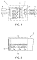
- the grid convergence solution computing system 2 includes, as principal components, a controller 3, a keyboard 4, a mouse 5, a display 6, and a printer 7.
- the controller 3 includes a microcomputer comprising a CPU 8, a ROM 9 and a RAM 10, a bus 11, an input/output interface (I/O interface) 12, drive circuits 13 and 14.
- the bus 11 connects the CPU 8, the ROM 9 and the RAM 10 to the I/O interface 12.
- the keyboard 4 and the mouse 5 are connected to the I/O interface 12.
- the display 6 and the printer 7 are connected through the drive circuits 13 and 14, respectively, to the I/O interface 12.
- a grid convergence solution computation program 15 shown in Fig. 2 is loaded from a magnetic medium, not shown, to the ROM 9. Input data is entered by operating the keyboard 4 and the mouse 5, the grid convergence computation program 15 (processing operation) is executed, and computed data obtained through the execution of the grid convergence computation program 15 is displayed by the display 6 or is printed out by the printer 7.
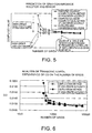
- Fig. 2 is a view of assistance in explaining the grid convergence solution computation program 15
- Fig. 3 is a diagram of a grid K generated by executing a grid-generating program 16 by the grid convergence computation system 2 and displayed on the screen of the display 6.
- the grid convergence computation program 15 includes the grid generation program 16 and a flow analysis program 17.
- the flow analysis program 17 includes a unit 17a for computing a computed value of high-order accuracy using a single grid, a unit 17b for computing a computed value of low-order accuracy using the same single grid, and a unit 17c for computing a grid convergence solution based on a relation between the computed value of high-order accuracy and the computed value of low-order accuracy.
- the number of grids corresponding to the processing ability of the CPU 8, and airfoil profile data are entered into the CPU 8 by operating the keyboard 4 and the mouse 5, and the grid generation program 16 is executed to generate the desired grid K.
- the grid K has a substantially rectangular shape and is defined by a plurality of radial lines L h , and a plurality of annular lines L k .
- the plurality of radial lines L h extend radially outward in directions perpendicular to the outline of the section of the airfoil, respectively.
- the plurality of annular lines L k are arranged radially outward at predetermined intervals around the outline.
- the plurality of radial lines L h intersect the plurality of annular lines L k .
- Data including conditions specifying flows including a lift coefficient is entered by operating the keyboard 4 and the mouse 5, and then the flow analysis program 17 is executed using the grid generated by carrying out the grid generation program 16 to analyze the drag coefficient CD of a typical two-dimensional section of, for example, a middle part of the airfoil.
- the flow analysis program 17 discretizes the Navier-Stokes equation expressing the flow of a viscous fluid by a partial differential equation by a difference calculus, and computes the grid convergence solution, such as a desired drag coefficient CD, of the discretized difference equation. Predictive computations are executed for a two-dimensional airfoil in a computational space for the grid convergence solution computation system 2.
- Fig. 4 is a flow chart of a computation method of computing a grid convergence solution
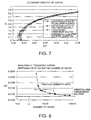
- Fig. 5 is a diagram showing the relation between a computed value of high-order accuracy computed by a computation method of high-order accuracy, a computed value of low-order accuracy computed by a computation method of low-order accuracy, and a grid convergence solution.
- the computation method of high-order accuracy is, for example, a third-order computation method accurate to the third-order term of the Taylor series development of a differential equation.
- the computation method of law order accuracy is, for example, a second-order computation method accurate to the second-order term.
- a single practical grid is generated in step s10, and then steps s11 and s13 are executed by parallel processing using the units 17a and 17b of the flow analysis program 17 shown in Fig. 2.
- the computation method of low-order accuracy is executed in step s11 using the unit 17b, a computed value A low of low-order accuracy is obtained in step s12, and then the computation method goes to step s15.
- the computation method of high-order accuracy is executed in step s13 using the unit 17a, a computed value A high of high-order accuracy is obtained in step s14, and then, the computation method goes to step s15.
- a grid convergence solution A conv and a predicted error E RR are computed by the unit 17c with using expressions (1) and (2).
- a conv A high + ⁇ (A high - A low )
- E RR ⁇ A high - A low
- ⁇ is a first constant determined for the computation method and meeting 0.1 ⁇ ⁇ ⁇ 10.0
- ⁇ is a second constant determined for the computation method and meeting 0.1 ⁇ ⁇ ⁇ 10.0.
- the first constant ⁇ and the second constant ⁇ are determined beforehand by processing the results of computations using some grids by statistical operations using the method of least squares and the method of calculating standard deviation.
- the first constant ⁇ can be determined by using Expression (3), which is a standard equation for the method of least squares. N types of grids respectively of different mesh sizes are prepared for a model problem, and computations of high-order accuracy and low-order accuracy are performed for the i-th grid (1 ⁇ i ⁇ N).
- a high (i) is a computed value obtained by the computation of high-order accuracy using the unit 17a
- a low (i) is a computed value obtained by the computation of low-order accuracy using the unit 17b.
- the linear simultaneous equations are solved for the first constant ⁇ and the variable A f .
- the second constant ⁇ is a standard deviation calculated by using Expression (4).
- the second constant ⁇ is multiplied by a constant in the range of 0.1 to 10 selected according to the allowable range of errors.
- Expression (1) for computing the grid convergence solution A conv the relation between the computed value A high of high-order accuracy, the computed value A low of low-order accuracy and the grid convergence solution A conv is substantially constant regardless of a degree of fineness or coarseness of the grid, i.e., for a single grid. Therefore, the ratio A high : A low : A conv is substantially constant for all the grids. Since the computed value A high of high-order accuracy approaches the grid convergence solution A conv than the computed value A low of low-order accuracy, the relation expressed by Expression (1) is realized necessarily.
- the grid convergence solution A conv can be computed by subtracting the computed value A low of low-order accuracy from the computed value A high of high-order accuracy to obtain a difference therebetween, multiplying the difference by the first constant ⁇ to obtain a product, and adding the computed value A high of high-order accuracy to the product.
- the grid convergence solution A conv thus computed is sent through the I/O interface 12 and the drive circuit 13 to the display 6 for displaying or through the I/O interface 12 and the drive circuit 14 to the printer 7 for printing.
- the grid convergence solution A conv is stored in the work memory, not shown, of the RAM 10. When necessary, the grid convergence solution A conv is read from the work memory and is give to the display 6 for displaying or to the printer 7 for printing.
- a predicted error ERR in the grid convergence solution A conv is computed by using Expression (2); the absolute value of the difference between the computed value A high of high-order accuracy and the computed value A low of low-order accuracy is computed, and the absolute value is multiplied by the second constant ⁇ to provide the predicted error ERR.
- the predicted error ERR is sent through the I/O interface 12 and the drive circuit 13 to the display 6 for displaying or through the I/O interface 12 and the drive circuit 14 to the printer 7 for printing.
- Fig. 6 is a graph showing the relation between the number of grids and drag coefficient CD for the typical two-dimensional section of a middle part of an airfoil, determined by computation.
- the first constant ⁇ and the second constant ⁇ are determined beforehand, the practical number of grids corresponding to the processing ability of the CPU 8, and data on the NACA 0012 airfoil are entered by operating the keyboard 4 and the mouse 5, and the grid generation program 16 is executed to generate a desired grid.
- the thus computed grid convergence solution at the drag coefficient CD is sent through the I/O interface 12 and the drive circuit 13 to the display 6 for displaying or through the I/O interface 12 and the drive circuit 14 to the printer 7 for printing.
- the convergence solution is stored in the work memory of the RAM 10 and is read from the work memory and sent to the display 6 or the printer 7 when necessary.
- a wind tunnel test model is formed on the basis of the grid convergence solution at the drag coefficient CD and other grid convergence solutions, the computed grid convergence solution and the results of wind tunnel tests are compared to see if the grid convergence solution obtained by the grid convergence solution computation system agrees satisfactorily with experimental results.
- the grid convergence solution computation system for computing the grid convergence solution A conv computes the computed value A high of high-order accuracy by the computational method of high-order accuracy using the unit 17a with the single grid, computes the computed value A low of low-order accuracy by the computational method of low-order accuracy using the unit 17b with the single grid, computes the grid convergence solution A conv on the basis of the relation between the computed value A high of high-order accuracy and the computed value A low of low-order accuracy on an assumption that the relation between the computed value A high of high-order accuracy, the computed value A low of low-order accuracy, and the grid convergence solution A conv is substantially constant regardless of a degree of fineness or coarseness of the grid, and displays the grid convergence solution A conv .
- the grid convergence solution computation system of the preferred embodiment according to the present invention is capable of computing the highly accurate grid convergence solution A conv using the number of computational grids far less than that of computational grids needed by the conventional computation system, does not need to generating a plurality of types grids respectively having different meshes for a computational space of a complicated shape and does not need much work time for generating a plurality of types of grids. More concretely, the grid convergence solution computation system of the preferred embodiment according to the present invention is capable of computing the highly accurate grid convergence solution A conv in a small fraction of time required by the conventional computation system. Thus, the grid convergence solution computation system of the present invention reduces greatly time necessary for designing and developing.
- the grid convergence solution computation system of the preferred embodiment according to the present invention subtracts the computed value A low of low-order accuracy from the computed value A high of high-order accuracy to obtain a difference therebetween, multiplies the difference by the first constant ⁇ to obtain a product, adds the computed value A high of high-order accuracy to the product to obtain the grid convergence solution A conv , and sends the grid convergence solution A conv to the display 6 for displaying or to the printer 7 for printing.
- the grid convergence solution computation system of the preferred embodiment according to the present invention determines the second constant ⁇ beforehand, computes the absolute value of the difference between the computed value A high of high-order accuracy and the computed value A low of low-order accuracy, multiplies the absolute value by the second constant ⁇ to compute the predicted error ERR, and sends the predicted error ERR to the display 6 for displaying or to the printer 7 for printing.
- Fig. 7 is a graph comparatively showing data on the lift/drag characteristic of an airfoil for an aircraft obtained by computation by the grid convergence solution computation methods and experiments.
- the grid convergence solution A conv and experimental values are shown for comparison.
- the grid convergence solution computation system of the present invention is applied to the prediction of the lift/drag characteristic of an airfoil for an aircraft. Since computed values and experimental values differ from each other in the condition of laminar-flow-to-turbulence transition, the experimental values are corrected by transition correction. In a medium lift range corresponding to a lift coefficient CL range of about 0.2 to 0.6, computed values of third-order accuracy is closer than computed values of second-order accuracy to the experimental values. It is known that the grid convergence solution computed by the grid convergence solution computing system agree substantially with the experimental value in the medium lift range.
- the grid convergence solution computation program 15 may be stored in a controller included in a supercomputer, a plurality of computers may be connected to the supercomputer, the computation program 15 may be executed using input data represented by input signals provided by the computers, and a grid convergence solution may be displayed by displays connected to the computers or printed out by printers connected to the computers.
Landscapes
- Engineering & Computer Science (AREA)
- Physics & Mathematics (AREA)
- Theoretical Computer Science (AREA)
- Geometry (AREA)
- General Physics & Mathematics (AREA)
- General Engineering & Computer Science (AREA)
- Computer Hardware Design (AREA)
- Evolutionary Computation (AREA)
- Computational Mathematics (AREA)
- Mathematical Analysis (AREA)
- Mathematical Optimization (AREA)
- Pure & Applied Mathematics (AREA)
- Aviation & Aerospace Engineering (AREA)
- Automation & Control Theory (AREA)
- Complex Calculations (AREA)
- Management, Administration, Business Operations System, And Electronic Commerce (AREA)
Applications Claiming Priority (2)
| Application Number | Priority Date | Filing Date | Title |
|---|---|---|---|
| JP2001401130A JP3621378B2 (ja) | 2001-12-28 | 2001-12-28 | 格子収束解の算出システム |
| JP2001401130 | 2001-12-28 |
Publications (2)
| Publication Number | Publication Date |
|---|---|
| EP1324233A2 true EP1324233A2 (de) | 2003-07-02 |
| EP1324233A3 EP1324233A3 (de) | 2005-05-25 |
Family
ID=19189732
Family Applications (1)
| Application Number | Title | Priority Date | Filing Date |
|---|---|---|---|
| EP02029022A Withdrawn EP1324233A3 (de) | 2001-12-28 | 2002-12-27 | System zum Berechnen einer Gitter-Konvergenzlösung |
Country Status (3)
| Country | Link |
|---|---|
| US (1) | US7069199B2 (de) |
| EP (1) | EP1324233A3 (de) |
| JP (1) | JP3621378B2 (de) |
Families Citing this family (4)
| Publication number | Priority date | Publication date | Assignee | Title |
|---|---|---|---|---|
| US6873946B1 (en) * | 1999-12-01 | 2005-03-29 | The United States Of America As Represented By The Secretary Of The Navy | Zeus code tool a method for implementing same and storage medium storing computer readable instructions for instantiating the zeus code tool |
| US20080004838A1 (en) * | 2005-12-08 | 2008-01-03 | The Johns Hopkins University | Air-Speed Wind Tunnel Data Analysis Suite |
| ES2351411B1 (es) * | 2008-09-03 | 2011-12-16 | Airbus Operations, S.L. | Métodos y sistemas para adaptar la topología de una malla estructurada multi-bloque de un objeto a una modificación de su geometría. |
| US20130218538A1 (en) * | 2012-02-20 | 2013-08-22 | Schlumberger Technology Corporation | Simulation model optimization |
Family Cites Families (8)
| Publication number | Priority date | Publication date | Assignee | Title |
|---|---|---|---|---|
| US4843563A (en) * | 1985-03-25 | 1989-06-27 | Canon Kabushiki Kaisha | Step-and-repeat alignment and exposure method and apparatus |
| US4809202A (en) * | 1985-12-27 | 1989-02-28 | Thinking Machines Corporation | Method and apparatus for simulating systems described by partial differential equations |
| JP2635617B2 (ja) * | 1987-09-29 | 1997-07-30 | 株式会社東芝 | 半導体素子特性評価用の直交格子点の発生方法 |
| JP3522408B2 (ja) * | 1995-09-18 | 2004-04-26 | 富士通株式会社 | 数値流体解析結果の誤差見積方法、数値流体解析結果の誤差見積装置、数値流体解析方法、及び数値流体解析装置 |
| US5729451A (en) * | 1995-12-01 | 1998-03-17 | Coleman Research Corporation | Apparatus and method for fusing diverse data |
| US5923329A (en) * | 1996-06-24 | 1999-07-13 | National Research Council Of Canada | Method of grid generation about or within a 3 dimensional object |
| US6014343A (en) * | 1996-10-31 | 2000-01-11 | Geoquest | Automatic non-artificially extended fault surface based horizon modeling system |
| US6356860B1 (en) * | 1998-10-08 | 2002-03-12 | Sandia Corporation | Method of grid generation |
-
2001
- 2001-12-28 JP JP2001401130A patent/JP3621378B2/ja not_active Expired - Fee Related
-
2002
- 2002-12-26 US US10/327,967 patent/US7069199B2/en not_active Expired - Lifetime
- 2002-12-27 EP EP02029022A patent/EP1324233A3/de not_active Withdrawn
Non-Patent Citations (4)
| Title |
|---|
| DE STERCK H ET AL: "Stationary two-dimensional magnetohydrodynamic flows with shocks: characteristic analysis and grid convergence study" JOURNAL OF COMPUTATIONAL PHYSICS ACADEMIC PRESS USA, vol. 166, no. 1, 1 January 2001 (2001-01-01), pages 28-62, XP002322734 ISSN: 0021-9991 * |
| ROACHE P J: "Perspective: a method for uniform reporting of grid refinement studies" TRANSACTIONS OF THE ASME. JOURNAL OF FLUIDS ENGINEERING USA, vol. 116, no. 3, September 1994 (1994-09), pages 405-413, XP008044971 ISSN: 0098-2202 * |
| ZHANG X D ET AL: "Numerical assessment of error estimators for Euler equations" AIAA JOURNAL AIAA USA, vol. 39, no. 9, September 2001 (2001-09), pages 1706-1715, XP008044968 ISSN: 0001-1452 * |
| ZINGG D W ET AL: "Comparison of several spatial discretizations for the Navier-Stokes equations" JOURNAL OF COMPUTATIONAL PHYSICS ACADEMIC PRESS USA, vol. 160, no. 2, 20 May 2000 (2000-05-20), pages 683-704, XP002322735 ISSN: 0021-9991 * |
Also Published As
| Publication number | Publication date |
|---|---|
| US20030139915A1 (en) | 2003-07-24 |
| JP3621378B2 (ja) | 2005-02-16 |
| JP2003196325A (ja) | 2003-07-11 |
| EP1324233A3 (de) | 2005-05-25 |
| US7069199B2 (en) | 2006-06-27 |
Similar Documents
| Publication | Publication Date | Title |
|---|---|---|
| US8452423B2 (en) | Methods and systems for the design and implementation of optimal multivariable model predictive controllers for fast-sampling constrained dynamic systems | |
| Strzodka et al. | Pipelined mixed precision algorithms on FPGAs for fast and accurate PDE solvers from low precision components | |
| EP2360606B1 (de) | Kostenoptimiertes verfahren für computerunterstützte berechnung der aerodynamischen kräfte in einem flugzeug | |
| Biancolini et al. | Glider fuselage-wing junction optimization using CFD and RBF mesh morphing | |
| US8239173B2 (en) | System for the computed-aided design of technical devices | |
| US20130226530A1 (en) | Mesh generation system | |
| Gumbert et al. | Effect of random geometric uncertainty on the computational design of a 3D flexible wing | |
| Giles | Monte Carlo evaluation of sensitivities in computational finance. | |
| Gauger et al. | Automatic differentiation of an entire design chain for aerodynamic shape optimization | |
| US9558301B1 (en) | Model-to-data and data-to-model traceability | |
| US7069199B2 (en) | Grid convergence solution computation system | |
| Munteanu et al. | Reduced-order-model approach for aeroelastic analysis involving aerodynamic and structural nonlinearities | |
| Bieterman et al. | An adaptive grid method for analysis of 3D aircraft configurations | |
| Baker et al. | An introduction to TITAN2 | |
| Sheshanarayana et al. | Efficient methods to build structural performance envelopes in characteristic load space | |
| US11106987B2 (en) | Forecasting systems | |
| US8483999B2 (en) | Method and system for simplifying models | |
| Roos | Generation of flexible aircraft LFT models for robustness analysis | |
| JPH08305735A (ja) | 部品コスト見積り方法および部品コスト見積り装置 | |
| Hristov et al. | How to Exploit What We Know About Input and Model: A Trans-probabilistic Approach to the 2022 AIAA UQ Challenge | |
| KR102878304B1 (ko) | 유도탄에 대한 유동 해석의 전처리, 해석 및 후처리 자동화 방법 | |
| US7058553B1 (en) | Method and system for pre-processing | |
| Gimeno et al. | Using automatic differentiation to compute periodic orbits of delay differential equations | |
| US20050165563A1 (en) | Methods and systems for predicting fuel sensor performance within a tank during motion | |
| Banga et al. | Direct calculation of likelihood-based benchmark dose levels for quantitative responses |
Legal Events
| Date | Code | Title | Description |
|---|---|---|---|
| PUAI | Public reference made under article 153(3) epc to a published international application that has entered the european phase |
Free format text: ORIGINAL CODE: 0009012 |
|
| 17P | Request for examination filed |
Effective date: 20021227 |
|
| AK | Designated contracting states |
Designated state(s): AT BE BG CH CY CZ DE DK EE ES FI FR GB GR IE IT LI LU MC NL PT SE SI SK TR |
|
| AX | Request for extension of the european patent |
Extension state: AL LT LV MK RO |
|
| PUAL | Search report despatched |
Free format text: ORIGINAL CODE: 0009013 |
|
| AK | Designated contracting states |
Kind code of ref document: A3 Designated state(s): AT BE BG CH CY CZ DE DK EE ES FI FR GB GR IE IT LI LU MC NL PT SE SI SK TR |
|
| AX | Request for extension of the european patent |
Extension state: AL LT LV MK RO |
|
| AKX | Designation fees paid |
Designated state(s): DE FR GB |
|
| STAA | Information on the status of an ep patent application or granted ep patent |
Free format text: STATUS: THE APPLICATION HAS BEEN WITHDRAWN |
|
| 18W | Application withdrawn |
Effective date: 20080226 |