EP1323223B1 - Moto-reducteur commute sur un signal de position absolu - Google Patents
Moto-reducteur commute sur un signal de position absolu Download PDFInfo
- Publication number
- EP1323223B1 EP1323223B1 EP01976367A EP01976367A EP1323223B1 EP 1323223 B1 EP1323223 B1 EP 1323223B1 EP 01976367 A EP01976367 A EP 01976367A EP 01976367 A EP01976367 A EP 01976367A EP 1323223 B1 EP1323223 B1 EP 1323223B1
- Authority
- EP
- European Patent Office
- Prior art keywords
- output shaft
- electric actuator
- actuator according
- motor
- rotor
- Prior art date
- Legal status (The legal status is an assumption and is not a legal conclusion. Google has not performed a legal analysis and makes no representation as to the accuracy of the status listed.)
- Expired - Lifetime
Links
- 230000001360 synchronised effect Effects 0.000 claims abstract description 7
- 239000003638 chemical reducing agent Substances 0.000 claims description 23
- 230000010363 phase shift Effects 0.000 claims description 5
- 238000001514 detection method Methods 0.000 claims description 3
- 239000000523 sample Substances 0.000 description 17
- 244000007853 Sarothamnus scoparius Species 0.000 description 5
- 239000000243 solution Substances 0.000 description 5
- 230000005355 Hall effect Effects 0.000 description 2
- 238000010586 diagram Methods 0.000 description 2
- 230000000694 effects Effects 0.000 description 2
- 210000000056 organ Anatomy 0.000 description 2
- 238000004378 air conditioning Methods 0.000 description 1
- 238000004364 calculation method Methods 0.000 description 1
- 230000001939 inductive effect Effects 0.000 description 1
- 238000011423 initialization method Methods 0.000 description 1
- 238000002347 injection Methods 0.000 description 1
- 239000007924 injection Substances 0.000 description 1
- 230000010354 integration Effects 0.000 description 1
- 238000000034 method Methods 0.000 description 1
- 235000001954 papillon Nutrition 0.000 description 1
- 244000229285 papillon Species 0.000 description 1
- 230000003252 repetitive effect Effects 0.000 description 1
- 238000004804 winding Methods 0.000 description 1
Images




Classifications
-
- F—MECHANICAL ENGINEERING; LIGHTING; HEATING; WEAPONS; BLASTING
- F02—COMBUSTION ENGINES; HOT-GAS OR COMBUSTION-PRODUCT ENGINE PLANTS
- F02D—CONTROLLING COMBUSTION ENGINES
- F02D11/00—Arrangements for, or adaptations to, non-automatic engine control initiation means, e.g. operator initiated
- F02D11/06—Arrangements for, or adaptations to, non-automatic engine control initiation means, e.g. operator initiated characterised by non-mechanical control linkages, e.g. fluid control linkages or by control linkages with power drive or assistance
- F02D11/10—Arrangements for, or adaptations to, non-automatic engine control initiation means, e.g. operator initiated characterised by non-mechanical control linkages, e.g. fluid control linkages or by control linkages with power drive or assistance of the electric type
-
- H—ELECTRICITY
- H02—GENERATION; CONVERSION OR DISTRIBUTION OF ELECTRIC POWER
- H02K—DYNAMO-ELECTRIC MACHINES
- H02K29/00—Motors or generators having non-mechanical commutating devices, e.g. discharge tubes or semiconductor devices
- H02K29/06—Motors or generators having non-mechanical commutating devices, e.g. discharge tubes or semiconductor devices with position sensing devices
- H02K29/08—Motors or generators having non-mechanical commutating devices, e.g. discharge tubes or semiconductor devices with position sensing devices using magnetic effect devices, e.g. Hall-plates, magneto-resistors
-
- H—ELECTRICITY
- H02—GENERATION; CONVERSION OR DISTRIBUTION OF ELECTRIC POWER
- H02K—DYNAMO-ELECTRIC MACHINES
- H02K7/00—Arrangements for handling mechanical energy structurally associated with dynamo-electric machines, e.g. structural association with mechanical driving motors or auxiliary dynamo-electric machines
- H02K7/10—Structural association with clutches, brakes, gears, pulleys or mechanical starters
- H02K7/116—Structural association with clutches, brakes, gears, pulleys or mechanical starters with gears
-
- F—MECHANICAL ENGINEERING; LIGHTING; HEATING; WEAPONS; BLASTING
- F02—COMBUSTION ENGINES; HOT-GAS OR COMBUSTION-PRODUCT ENGINE PLANTS
- F02D—CONTROLLING COMBUSTION ENGINES
- F02D11/00—Arrangements for, or adaptations to, non-automatic engine control initiation means, e.g. operator initiated
- F02D11/06—Arrangements for, or adaptations to, non-automatic engine control initiation means, e.g. operator initiated characterised by non-mechanical control linkages, e.g. fluid control linkages or by control linkages with power drive or assistance
- F02D11/10—Arrangements for, or adaptations to, non-automatic engine control initiation means, e.g. operator initiated characterised by non-mechanical control linkages, e.g. fluid control linkages or by control linkages with power drive or assistance of the electric type
- F02D2011/101—Arrangements for, or adaptations to, non-automatic engine control initiation means, e.g. operator initiated characterised by non-mechanical control linkages, e.g. fluid control linkages or by control linkages with power drive or assistance of the electric type characterised by the means for actuating the throttles
- F02D2011/102—Arrangements for, or adaptations to, non-automatic engine control initiation means, e.g. operator initiated characterised by non-mechanical control linkages, e.g. fluid control linkages or by control linkages with power drive or assistance of the electric type characterised by the means for actuating the throttles at least one throttle being moved only by an electric actuator
Definitions
- the present invention relates to the field of actuators with geared motors, comprising an engine electric coupled to a gear reduction mechanism.
- Actuator means a means in rotation of an organ, whose stroke is less than 360 °.
- the function of an actuator is to ensure accurate angular positioning and repetitive, under the control of a control circuit. he differs from an engine whose function is to make rotate an organ at a given speed of rotation, under form of n turns per minute without angular limit.
- the sensor described in this art document provides two sinusoidal signals out of phase by 90 °, which are relative position signals and not absolute.
- Brushless DC motors (brushless motors) are known in the state of the art since many years, in polyphase variants various, and we will find in Figure 1 a view of such three-phase motor (100) described in US Pat. No. 5,880,551 to the plaintiff.
- Figure 1 a view of such three-phase motor (100) described in US Pat. No. 5,880,551 to the plaintiff.
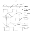
- the position of the 3 Hall effect probes (1), (2), (3) placed at the inside of the toothing (18), which will deliver, as indicated in fig. 2, 3 phase-shifted signals of 120 ° ((4), (5), (6)) as well as the phase shift of these probe signals versus torque constants ((7), (8), (9)) of the 3 phases ((19), (20), (21)) of FIG.
- Such sets require a circuit control electronics receiving on the one hand a signal input from the position feedback sensor angular of the output shaft, and other by the signals input from each of the Hall probes.
- US-A-5 452 697 discloses an electric actuator corresponding to the preamble of claim 1.
- the object of the present invention is to avoid both the disadvantages of the broom motor actuators, and brushless motor actuators, by offering a actuator comprising a brushless motor not requiring that a reduced number of wiring wires.
- Such an actuator according to the invention exploits the presence of the potentiometric sensor, or contactless, of copy of the output shaft position to deduce the rotor position of the synchronous motor brushless, and allows thus to reduce the number of probes and thus of connections required.
- the auto-switching of the brushless motor does not does more by position information taken directly on the rotor of the engine but by position information indirect output of the application.
- the invention more general an electric actuator consisting of at least a brushless synchronous motor autocommuted at P phases, P being an integer between 1 and 6, and N pairs of rotor poles, where N is a whole number greater than or equal to to 1, the actuator comprising a position sensor whose output signal controls an electronic circuit of engine control, the rotor of said engine driving a ratio reduction mechanism R, the travel of the output shaft of the speed reducer being less than 360 °, characterized in that that said absolute position sensor is coupled [no not to the rotor but] to the output shaft of the gearbox for measure the absolute angular position of the output shaft of the reducer, the electronic circuit comprising a circuit sequential control of the current of each of the phases performing an automatic sequence switching supply phase according to position absolute of the output shaft of the gearbox.
- absolute position sensor we mean a position sensor comprising reference means ensuring an invariable reference position, providing a information never taking twice the same value on the race, unlike an incremental sensor.
- the sensor implemented by the invention is a sensor providing a signal corresponding to a function injective of the angular position, that is to say a sensor whose any output signal value is the image of at most an angular position value on the stroke of the tree output of the reducer.
- This reference means may be constituted by means for returning the output shaft ensuring a clearing the game
- the sensor driven by the output shaft of the reducer delivers a signal corresponding to a function injective of the angular position of said output shaft.
- the reference means is constituted by an additional position sensor driven directly by the motor rotor. This sensor additional position delivers a synchronization signal of the motor control circuit.
- said speed reducer mechanics has a reduction ratio R greater than 2.
- the means of reminder of the shaft is constituted by a spiral spring of which one of the ends is integral with the output shaft and the other end is secured to a fixed point.
- the mechanical speed reducer has a lower clearance at 180 / (N.P.R)
- the position sensor presents a resolution r less than 180 / (N.P.R) degrees.
- the circuit electronics has an input to receive the signal delivered by the absolute position sensor of the shaft of output of the reducer, and P outputs each delivering one pilot signal of one of the P phases of the engine, with a phase shift of 360 / P between two consecutive phases, N designating the number of pairs of motor poles.
- the electronic circuit further comprises an input of resetting receiving a signal delivered by a sensor additional position driven directly by the rotor.
- the electronic circuit further comprises an input for receiving a signal of reference corresponding to the desired angular position, the electronic circuit performing a first loop of servo acting on the intensity of the engine torque and a second auto-switching loop controlling the current states in the motor phases.
- the electronics of phase control consists of a power stage with transistors driven by a logic control stage imposing the feeding sequence and the amplitude of the current of the P phases.
- the logic control stage is consisting of a microcontroller having at least P outputs of the PWM type to independently adjust the current of each of the P phases.
- the phase control electronics has a sequence initialization, on power up, on a position reference defined by the return spring.
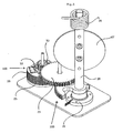
- the invention described by way of example in this following includes a three-phase motor (100) with 5 pairs of poles such as the one shown in Figure 1. It includes known manner a stator (25) having three stator blooms excited by coils electric (19).
- the rotor (22) has 5 pairs of poles and has an alternation of thin magnetic magnets radially, in alternating directions. He drives a wheel toothed (50) driving the speed reducer (200) consisting of a gear train.
- the output shaft (28) of the geared motor supports in the example described a butterfly valve (27).
- a return spring (34) constituted by a spiral spring acts on the output shaft (28).
- the race of the output shaft (28) is less than 360 °.
- the output shaft drives directly a position sensor (24) shown in detail in FIG.
- This position sensor is constituted by a stator (60) and a rotor (61) comprising two thin magnets (62, 63) of semi-tubular shape, magnetized radially in opposite directions.
- the stator (60) presents in the example described two gaps (64, 65) in which two probes of Hall (66, 67).
- This sensor (24) delivers signals representative of the actual angular position of the tree output (28) of the gear motor.
- the signal delivered by such a sensor absolute position is equivalent to that of a sensor potentiometric and is an analog signal constituted by a voltage substantially proportional to the position angular, with a resolution less than 0.1 °.
- the absolute position sensor delivers 2 signals redundant (25, 26) (fig.10).
- the engine control (100) requires a change of state every 12 ° for a three-phase motor at 5 pairs of poles, which corresponds to a condition of change of state every 180 / (N.P) degrees for the auto-switching of a P-phase motor and N pairs of poles to the rotor.
- the sensor 24 supplies an injective function signal of the angular position of the motor (100). If we neglect the clearance j of the gearbox, a position increment ( ⁇ - ⁇ 0 ) on the output shaft corresponds to a position increment R. ( ⁇ - ⁇ 0 ) to the rotor of the motor. In order to be able to perform the auto-switch with an actuator according to the example described, it is necessary for a change of state to occur for each increment of rotor position equal to 12 °.
- the reduction ratio R is worth substantially 20. So the resolution r required at the sensor will be 0.6 °. It is important to know that the resolutions typical of these sensors are of the order of 0.15 °.
- Figure 7 shows a first variant of the invention, where the output signal of the sensor (24) is converted, using the digital analog converter (29) into a digital signal.
- This digital signal is then processed by a decoder responsible for providing 3 tracks SA, SB, SC (30), (31), (32) signals (4), (5), (6) equivalent to those of the probes (1), (2), (3) of Figures 1 and 2.
- Switching electronics provides the rotor position information to the control logic for auto-switching. We see the advantage of this solution that removes the 3 wires from the probes, and to not have to go out in the direction of electronics switching logic, which is often remote, 3 signals probes that are sensitive to disturbances electromagnetic.
- Figure 8 shows a second variant of the invention, more efficient, whose purpose is always remove the 3 Hall effect probes ((1), (2), (3)), but without having to recreate information identical to these 3 probe signals.
- the angle ⁇ (t) is the desired position for the output shaft (28) of the application described in FIG. 5 consisting of a three-phase motor with N pairs of poles, a ratio reducer R and a potentiometer, when one feeds the 3 phases with the voltages Ua, Ub, Uc.
- N.R. ⁇ (t) referred to within a period 360 ° electric current according to currents Ia, Ib and Ic through each of the phases (19), (20, (21), the constant pairs of each phase being spaced from 120 ° electric.
- the position ⁇ (t) of the output shaft is therefore can be controlled by the 3 signals PWMa, PWMb, PWMc, using a double loop of auto-switching and position control.
- FIG. 12 represents a view of a variant of the control circuit, comprising a detection element addition (51) placed in the engine and delivering a digital signal synchronization function of the position direct from the rotor.
- the engine (40) has a sensor additional (51) driven directly by the rotor and delivering a reference signal in addition to the signal of position provided by the absolute position sensor (50) driven by the output shaft (52).
- the output tree is biased by a return spring (53) compensating the game of the gear train.
- the additional sensor (51) is constituted by a Hall probe delivering a signal depending on the direct position of the motor shaft (45).
- the motor shaft rotates 5 turns for a rotation of the output shaft of the gearbox by 90 °.
- the output signal of the additional sensor (51) provides a timing signal (56) to the microcontroller (54) for recalibrating the signal (55) supplied by the absolute position sensor (50).
- the synchronization is performed in the example described 10 times per turn.
Landscapes
- Engineering & Computer Science (AREA)
- Power Engineering (AREA)
- Chemical & Material Sciences (AREA)
- Combustion & Propulsion (AREA)
- Mechanical Engineering (AREA)
- General Engineering & Computer Science (AREA)
- Control Of Motors That Do Not Use Commutators (AREA)
- Connection Of Motors, Electrical Generators, Mechanical Devices, And The Like (AREA)
- Transmission And Conversion Of Sensor Element Output (AREA)
- Steering Devices For Bicycles And Motorcycles (AREA)
Description
- un moteur synchrone sans balai (100) polyphasé possédant P phases et N paires de pôles au rotor (22)
- un réducteur de vitesse mécanique (23) à engrenages de rapport 1/R et de jeu angulaire j
- un ressort de rappel (34) sur une position de référence de l'arbre de sortie (28) appelée 0
- un capteur de position absolu (24) fournissant une
information de position exprimée en mV/°, ou dans le
cas de sorties PWM pouvant être traitée en mV/°, de
résolution r exprimée en degrés.
et est particulièrement adaptée au contrôle de vannes à course limitée dans le domaine automobile. On trouvera à la figure 5 un descriptif de l'application type pour une vanne papillon d'admission d'air (27).
- N désigne le nombre de paires de pôles au rotor
- P désigne le nombre de phases du rotor
- R désigne le rapport de réduction
- la figure 1 représente une vue schématique d'un actionneur selon l'art antérieur,
- la figure 2 représente les signaux électriques correspondant à un actionneur de l'art antérieur,
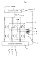
- les figures 3 et 4 représentent une vue du circuit de commande d'un actionneur selon l'art antérieur,
- la figure 5 représente une vue schématique d'un actionneur selon l'invention,
- la figure 6 représente une vue en détail du capteur de position entraíné par l'arbre de sortie,
- les figures 7 à 9 représentent une vue du circuit de commande d'un actionneur selon l'invention,
- la figure 10 représente les signaux de sortie du capteur de position,
- la figure 11 représente un diagramme électrique vectoriel d'un actionneur selon l'invention, pour une position visée (en l'occurrence 150° sur la figure),
- la figure 12 représente une vue d'une variante du circuit de commande, comportant un élément de détection additionnel (51) placé dans le moteur et délivrant un signal digital de synchronisation fonction de la position directe du rotor.
- N désigne le nombre de paires de pôles au rotor
- P désigne le nombre de phases du rotor
- R désigne le rapport de réduction.
- la boucle d'asservissement de position classique identique à celle d'un moteur à courant continu, chargée de créer un effet sur l'intensité du couple moteur disponible et sur son signe
- la boucle d'autocommutation autorisant le passage d'un état de courant dans les phases P du moteur à l'état suivant, avec une avance de phase réglable comme expliqué plus loin à la figure 11.
- un sens de rotation du rotor défini par la séquence d'alimentation des phases et un réglage de l'intensité du courant dans chacune des phases (mode asservissement de position).
- La détermination en fonction de la position du rotor du prochain état de courant dans les phases, avec un déphasage position actuelle/position visée réglable en fonction de la vitesse de rotation du rotor (mode autocommutation).
- Ua = U cos N.R.(t) pour la phase A
- Ub = U cos (N.R.(t) + 120°) pour la phase B
- Uc = U cos (N.R.(t) + 240°) pour la phase C
- Ua = U cos α(t) pour la phase A
- Ub = U cos α(t) +120° pour la phase B
- Uc = U cos α(t) + 240°) pour la phase C,
- à aimant permanent
- hybride
- à réluctance variable
Claims (13)
- Actionneur électrique constitué d'au moins un moteur synchrone sans balais autocommuté à P phases, P étant un nombre entier compris entre 1 et 6, et N paires de pôles au rotor, N étant un nombre entier supérieur ou égal à 1, l'actionneur comprenant un capteur de position dont le signal de sortie commande un circuit électronique de pilotage séquentiel du courant de chacune des phases, le rotor dudit moteur entraínant un mécanisme réducteur de vitesse de rapport R, la course de l'arbre de sortie du réducteur de vitesse étant inférieure à 360° caractérisé en ce que ledit capteur de position absolu est accouplé [non pas au rotor mais] à l'arbre de sortie du réducteur pour mesurer la position angulaire absolue de l'arbre de sortie du réducteur, le susdit circuit électronique de pilotage réalisant une commutation automatique des séquences d'alimentation des phases en fonction de la position absolue de l'arbre de sortie du réducteur.
- Actionneur électrique selon la revendication 1 caractérisé en ce qu'il comporte un élément de détection additionnel (51), délivrant un signal de synchronisation fonction de la position directe du rotor.
- Actionneur électrique selon la revendication 1 ou 2 caractérisé en ce que le capteur entraíné par l'arbre de sortie du réducteur délivre un signal correspondant à une fonction injective de la position angulaire dudit arbre de sortie.
- Actionneur électrique selon la revendication 1, 2 ou 3 caractérisé en ce que ledit réducteur de vitesse comporte un moyen de rappel de l'arbre de sortie dans une position angulaire de référence.
- Actionneur électrique selon la revendication 4 caractérisé en ce que le moyen de rappel de l'arbre est constitué par un ressort spiral dont l'une des extrémités est solidaire de l'arbre de sortie et l'autre extrémité est solidaire d'un point fixe.
- Actionneur électrique selon la revendication 1, 2 ou 3 caractérisé en ce que le réducteur mécanique de vitesse présente un jeu inférieur à 180/(N.P.R).
- Actionneur électrique selon l'une quelconque des revendications précédentes caractérisé en ce que le capteur de position présente une résolution r inférieure à 180/(N.P.R) degrés.
- Actionneur électrique selon l'une quelconque des revendications précédentes caractérisé en ce que le circuit électronique comporte une entrée pour recevoir le signal délivré par le capteur de position absolue de l'arbre de sortie du réducteur, et P sorties délivrant chacune un signal de pilotage de l'une des P phases du moteur, avec un déphasage de 360/P entre deux phases consécutives.
- Actionneur électrique selon la revendication 8 caractérisé en ce que le circuit électronique comporte en outre une entrée pour recevoir un signal de référence correspondant à la position angulaire désirée, le circuit électronique réalisant une première boucle d'asservissement agissant sur l'intensité du couple moteur et une deuxième boucle d'autocommutation commandant les états de courant dans les phases du moteur.
- Actionneur électrique selon l'une quelconque des revendications précédentes caractérisé en ce que l'électronique de pilotage des phases est constitué d'un étage de puissance à transistors pilotés par un étage de contrôle logique imposant la séquence d'alimentation et l'amplitude du courant des P phases.
- Actionneur électrique selon l'une quelconque des revendications précédentes caractérisé en ce que l'étage de contrôle logique est constitué d'un microcontrôleur possédant au moins P sorties du type PWM permettant de régler de façon indépendante le courant de chacune des P phases.
- Actionneur électrique selon l'une quelconque des revendications précédentes caractérisé en ce que l'électronique de pilotage des phases possède une séquence d'initialisation, à la mise sous tension, sur une position de référence définie par le ressort de rappel.
- Actionneur électrique selon l'une quelconque des revendications précédentes, caractérisé en ce que ledit réducteur de vitesse mécanique présente un rapport de réduction R supérieur à 2.
Applications Claiming Priority (3)
| Application Number | Priority Date | Filing Date | Title |
|---|---|---|---|
| FR0012829 | 2000-10-06 | ||
| FR0012829A FR2815189B1 (fr) | 2000-10-06 | 2000-10-06 | Moto-reducteur electrique sans balai autocommute sur un signal de position absolu |
| PCT/FR2001/003081 WO2002029959A1 (fr) | 2000-10-06 | 2001-10-05 | Moto-reducteur commute sur un signal de position absolu |
Publications (2)
| Publication Number | Publication Date |
|---|---|
| EP1323223A1 EP1323223A1 (fr) | 2003-07-02 |
| EP1323223B1 true EP1323223B1 (fr) | 2005-07-27 |
Family
ID=8855098
Family Applications (1)
| Application Number | Title | Priority Date | Filing Date |
|---|---|---|---|
| EP01976367A Expired - Lifetime EP1323223B1 (fr) | 2000-10-06 | 2001-10-05 | Moto-reducteur commute sur un signal de position absolu |
Country Status (7)
| Country | Link |
|---|---|
| US (1) | US7304450B2 (fr) |
| EP (1) | EP1323223B1 (fr) |
| JP (1) | JP2004515187A (fr) |
| AT (1) | ATE300803T1 (fr) |
| DE (1) | DE60112316T2 (fr) |
| FR (1) | FR2815189B1 (fr) |
| WO (1) | WO2002029959A1 (fr) |
Families Citing this family (30)
| Publication number | Priority date | Publication date | Assignee | Title |
|---|---|---|---|---|
| DE10204199A1 (de) * | 2002-02-01 | 2003-08-07 | Pierburg Gmbh | Steuereinrichtung für einen Motor zur Verstellung eines Stellorgans |
| DK1751845T3 (en) * | 2004-06-04 | 2016-02-15 | Belimo Holding Ag | Brushless dc motor |
| KR101397210B1 (ko) * | 2005-06-28 | 2014-05-21 | 스트리커 코포레이션 | 모터 로터의 상태를 모니터링하는 센서를 포함하는 동력이 있는 수술 도구용 제어 어셈블리 |
| EP1911951A1 (fr) * | 2006-10-10 | 2008-04-16 | Magneti Marelli Powertrain S.p.A. | Papillon des gaz avec moteur sans balai triphasé pour moteur à combustion interne |
| FR2919441B1 (fr) | 2007-07-24 | 2010-01-29 | Moving Magnet Tech Mmt | Moto-reducteur comportant un moteur electrique polyphase compact |
| DE502008000945D1 (de) * | 2008-05-09 | 2010-08-26 | Micronas Gmbh | Integrierte Schaltung zum Ansteuern eines Elektromotors |
| DE102008030005A1 (de) * | 2008-06-24 | 2009-12-31 | Mahle International Gmbh | Aktuator |
| DE102008031620A1 (de) | 2008-07-07 | 2010-01-14 | Continental Automotive Gmbh | Verfahren und Vorrichtung zur Ansteuerung von bürstenlosen (EC)-Elektromotoren |
| WO2010027447A2 (fr) * | 2008-09-08 | 2010-03-11 | Cts Corporation | Actionneur à courant continu sans balais |
| FR2936307B1 (fr) | 2008-09-24 | 2010-09-17 | Moving Magnet Tech Mmt | Capteur de position lineaire ou rotatifa aimant permanent pour la detection d'une cible ferromagnetique |
| FR2937722B1 (fr) | 2008-10-24 | 2010-11-26 | Moving Magnet Tech Mmt | Capteur de position magnetique a mesure de direction de champ et a collecteur de flux |
| FR2945388B1 (fr) | 2009-05-11 | 2013-04-12 | Moving Magnet Technologies M M T | Moteur electrique triphase a faible couple de detente |
| US8680727B2 (en) * | 2009-05-27 | 2014-03-25 | Cts Corporation | Brushless direct current actuator with clip for retaining bobbins |
| FR2947902B1 (fr) | 2009-07-07 | 2011-07-22 | Moving Magnet Technologies M M T | Capteur de position absolue et multi-periodique |
| FR2952430B1 (fr) | 2009-11-06 | 2012-04-27 | Moving Magnet Technologies M M T | Capteur de position magnetique bidirectionnel a rotation de champ |
| US8525460B2 (en) * | 2010-02-02 | 2013-09-03 | GM Global Technology Operations LLC | Architecture for robust force and impedance control of series elastic actuators |
| US20110203769A1 (en) * | 2010-02-24 | 2011-08-25 | Douglas Edward Cors | Cooling System for Actuator |
| FR2965347B1 (fr) | 2010-09-29 | 2015-04-03 | Moving Magnet Tech | Capteur de position ameliore |
| FR2999825B1 (fr) | 2012-12-13 | 2015-01-02 | Moving Magnet Tech | Ensemble mecatronique pour l'entrainement d'un organe exterieur utilisant un moteur sans balai et un ensemble simple de composants electroniques |
| US9803731B2 (en) * | 2014-04-24 | 2017-10-31 | American Axle & Manufacturing, Inc. | Actuator device having cam and follower and controller configured to employ rate-based methodology to identify positioning of follower on cam at predetermined location |
| FR3021819B1 (fr) * | 2014-06-03 | 2016-06-03 | Mmt Sa | Actionneur lineaire reversible auto commute a commande bifilaire |
| FR3022414B1 (fr) * | 2014-06-12 | 2016-07-01 | Mmt Sa | Ensemble mecatronique pour l'entrainement d'un organe exterieur utilisant un moteur sans balai et un ensemble simple de composants electroniques. |
| FR3029037B1 (fr) * | 2014-11-20 | 2019-01-25 | Mmt Sa | Ensemble mecatronique pilote par un signal de couple et direction distinct du signal de puissance. |
| DE102015105526A1 (de) * | 2015-04-10 | 2016-10-13 | Wittenstein Ag | Antrieb und Verfahren zum Betreiben eines Antriebs |
| DE102015210648A1 (de) * | 2015-06-10 | 2016-12-15 | Siemens Schweiz Ag | Stellantrieb |
| FR3060892B1 (fr) * | 2016-12-21 | 2021-01-22 | Mmt ag | Actionneur mecatronique |
| FR3062701B1 (fr) | 2017-02-06 | 2019-06-07 | Mmt ag | Vanne motorisee a boisseau |
| CN111034012B (zh) * | 2017-08-31 | 2023-09-19 | 三菱电机株式会社 | 致动器的控制装置及控制方法 |
| FR3079983B1 (fr) * | 2018-04-09 | 2020-04-10 | Moving Magnet Technologies | Procede de commande d’un moteur polyphase |
| EP4346071A1 (fr) | 2022-09-28 | 2024-04-03 | Ratier-Figeac SAS | Système de moteur électrique |
Family Cites Families (23)
| Publication number | Priority date | Publication date | Assignee | Title |
|---|---|---|---|---|
| DE3039090A1 (de) * | 1980-10-16 | 1982-07-15 | Reinhard Ing.(grad.) 8000 München Krämer | Luft-steuerorgan fuer brennkraftmaschine |
| US4692674A (en) * | 1985-04-26 | 1987-09-08 | The United States Of America As Represented By The Administrator Of The National Aeronautics And Space Administration | Brushless DC motor control system responsive to control signals generated by a computer or the like |
| JP2845884B2 (ja) * | 1988-03-30 | 1999-01-13 | 株式会社日立製作所 | スロツトルセンサとその温度補償方法 |
| EP0414941B1 (fr) * | 1989-08-30 | 1993-07-28 | Siemens Aktiengesellschaft | Dispositif de commande de la position d'un équipement |
| US5334898A (en) * | 1991-09-30 | 1994-08-02 | Dymytro Skybyk | Polyphase brushless DC and AC synchronous machines |
| US6198275B1 (en) * | 1995-06-07 | 2001-03-06 | American Electronic Components | Electronic circuit for automatic DC offset compensation for a linear displacement sensor |
| JP2859049B2 (ja) * | 1992-09-17 | 1999-02-17 | 株式会社日立製作所 | 内燃機関の絞り弁制御装置 |
| US5493191A (en) * | 1994-09-19 | 1996-02-20 | Eaton Corporation | B-type actuator with time out |
| DE19608756C2 (de) * | 1995-03-06 | 1998-07-02 | Hitachi Ltd | Ventilsteuervorrichtung für ein Kraftfahrzeug |
| DE19513692C1 (de) * | 1995-04-11 | 1996-07-18 | Stegmann Max Antriebstech | Drehwinkelmeßsystem |
| JP3498455B2 (ja) * | 1995-12-08 | 2004-02-16 | 日産自動車株式会社 | スロットルバルブの位置決め制御装置 |
| JPH09322584A (ja) * | 1996-05-27 | 1997-12-12 | Matsushita Electric Ind Co Ltd | 減速機付きモータおよびその制御装置 |
| US5992383A (en) * | 1996-05-28 | 1999-11-30 | U.S. Philips Corporation | Control unit having a disturbance predictor, a system controlled by such a control unit, an electrical actuator controlled by such a control unit, and throttle device provided with such an actuator |
| JP3543896B2 (ja) * | 1996-06-20 | 2004-07-21 | 三菱電機株式会社 | エンジンの吸入空気量制御装置 |
| US5829115A (en) * | 1996-09-09 | 1998-11-03 | General Electro Mechanical Corp | Apparatus and method for actuating tooling |
| JPH10225190A (ja) * | 1997-02-04 | 1998-08-21 | Sanden Corp | 回転駆動装置 |
| US5847530A (en) * | 1997-08-28 | 1998-12-08 | Barber Colman | Systems and methods for torque control of actuator and brushless DC motor therein |
| US6194856B1 (en) * | 1999-01-25 | 2001-02-27 | Hitachi, Ltd. | Motor driving apparatus including a modularized current control circuit and method of controlling the same |
| US6288534B1 (en) * | 1999-02-10 | 2001-09-11 | Cts Corporation | Non-contacting throttle valve position sensor |
| JP3929665B2 (ja) * | 1999-12-28 | 2007-06-13 | 三菱電機株式会社 | エンジンの吸入空気量制御装置 |
| US6398330B1 (en) * | 2000-01-04 | 2002-06-04 | Hewlett-Packard Company | Apparatus for controlling pen-to-print medium spacing |
| FR2829986B1 (fr) * | 2001-09-26 | 2003-12-26 | Roulements Soc Nouvelle | Systeme de direction assistee electrique commande par impulsions |
| FI113108B (fi) * | 2002-03-07 | 2004-02-27 | Abb Oy | Menetelmä ja laitteisto puhallinmoottorin ohjaamiseksi |
-
2000
- 2000-10-06 FR FR0012829A patent/FR2815189B1/fr not_active Expired - Fee Related
-
2001
- 2001-10-05 US US10/381,739 patent/US7304450B2/en not_active Expired - Lifetime
- 2001-10-05 EP EP01976367A patent/EP1323223B1/fr not_active Expired - Lifetime
- 2001-10-05 DE DE60112316T patent/DE60112316T2/de not_active Expired - Lifetime
- 2001-10-05 AT AT01976367T patent/ATE300803T1/de not_active IP Right Cessation
- 2001-10-05 JP JP2002533461A patent/JP2004515187A/ja active Pending
- 2001-10-05 WO PCT/FR2001/003081 patent/WO2002029959A1/fr not_active Ceased
Also Published As
| Publication number | Publication date |
|---|---|
| JP2004515187A (ja) | 2004-05-20 |
| FR2815189A1 (fr) | 2002-04-12 |
| US20040085041A1 (en) | 2004-05-06 |
| US7304450B2 (en) | 2007-12-04 |
| FR2815189B1 (fr) | 2003-01-03 |
| DE60112316T2 (de) | 2006-05-24 |
| EP1323223A1 (fr) | 2003-07-02 |
| ATE300803T1 (de) | 2005-08-15 |
| WO2002029959A1 (fr) | 2002-04-11 |
| DE60112316D1 (de) | 2005-09-01 |
Similar Documents
| Publication | Publication Date | Title |
|---|---|---|
| WO2002029959A1 (fr) | Moto-reducteur commute sur un signal de position absolu | |
| FR2811824A1 (fr) | Moteur electrique a deux modes de communication d'alimentation | |
| EP1298785B1 (fr) | Dispositif de commande d'un moteur à commutation électronique | |
| EP1408603B1 (fr) | Dispositif de pilotage d'un moteur à commutation electronique au moyen d'un signal de position | |
| EP3516764B1 (fr) | Moto-réducteur, système d'essuyage et proédé de commande associés | |
| EP3542450A1 (fr) | Moto-reducteur, systeme d'essuyage et procede de commande associes | |
| FR2829986A1 (fr) | Systeme de direction assistee electrique commande par impulsions | |
| FR2999825A1 (fr) | Ensemble mecatronique pour l'entrainement d'un organe exterieur utilisant un moteur sans balai et un ensemble simple de composants electroniques | |
| EP1407528B1 (fr) | Moteur polyphase | |
| US6741048B2 (en) | Pulse-controlled electronically commutated motor | |
| EP3155717A2 (fr) | Ensemble mécatronique pour l'entraînement d'un organe extérieur utilisant un moteur sans balai et un ensemble simple de composants électroniques | |
| WO2017089697A1 (fr) | Procédé de commande d'une machine synchrone à aimants permanents, et dispositif correspondant | |
| US7146944B2 (en) | Valve timing controller | |
| EP1776593A2 (fr) | Dispositif de commande d'une machine electrique tournante | |
| FR2724789A1 (fr) | Dispositif de commande d'un moteur synchrone | |
| WO2017153664A1 (fr) | Système de transmission magnétique | |
| EP0549429A1 (fr) | Rotor à aimants permanents doté d'une indication de sa position angulaire instantanée et machine magnéto-dynamique, comme un moteur sans collecteur, équipée d'un tel rotor | |
| EP3815239B1 (fr) | Moteur electrique a courant continu sans balai et procede de commande associe | |
| FR2843248A1 (fr) | Procede de commande de fonctionnement synchronise d'au moins deux moteurs electriques polyphases | |
| EP3394978B1 (fr) | Procédé de commande pseudo-sinusoïdale d'un moteur électrique synchrone | |
| FR3100505A1 (fr) | Actionneur electrique d’un systeme de freinage d’un vehicule routier | |
| EP2416490A2 (fr) | Chaîne de traction pour un véhicule de transport, notamment ferroviaire, et procédé de commande d'une telle chaîne | |
| FR2743957A1 (fr) | Moteur electrique pas a pas reversible |
Legal Events
| Date | Code | Title | Description |
|---|---|---|---|
| PUAI | Public reference made under article 153(3) epc to a published international application that has entered the european phase |
Free format text: ORIGINAL CODE: 0009012 |
|
| 17P | Request for examination filed |
Effective date: 20030404 |
|
| AK | Designated contracting states |
Designated state(s): AT BE CH CY DE DK ES FI FR GB GR IE IT LI LU MC NL PT SE TR |
|
| GRAP | Despatch of communication of intention to grant a patent |
Free format text: ORIGINAL CODE: EPIDOSNIGR1 |
|
| GRAS | Grant fee paid |
Free format text: ORIGINAL CODE: EPIDOSNIGR3 |
|
| GRAA | (expected) grant |
Free format text: ORIGINAL CODE: 0009210 |
|
| AK | Designated contracting states |
Kind code of ref document: B1 Designated state(s): AT BE CH CY DE DK ES FI FR GB GR IE IT LI LU MC NL PT SE TR |
|
| PG25 | Lapsed in a contracting state [announced via postgrant information from national office to epo] |
Ref country code: IT Free format text: LAPSE BECAUSE OF FAILURE TO SUBMIT A TRANSLATION OF THE DESCRIPTION OR TO PAY THE FEE WITHIN THE PRESCRIBED TIME-LIMIT;WARNING: LAPSES OF ITALIAN PATENTS WITH EFFECTIVE DATE BEFORE 2007 MAY HAVE OCCURRED AT ANY TIME BEFORE 2007. THE CORRECT EFFECTIVE DATE MAY BE DIFFERENT FROM THE ONE RECORDED. Effective date: 20050727 Ref country code: TR Free format text: LAPSE BECAUSE OF FAILURE TO SUBMIT A TRANSLATION OF THE DESCRIPTION OR TO PAY THE FEE WITHIN THE PRESCRIBED TIME-LIMIT Effective date: 20050727 Ref country code: AT Free format text: LAPSE BECAUSE OF FAILURE TO SUBMIT A TRANSLATION OF THE DESCRIPTION OR TO PAY THE FEE WITHIN THE PRESCRIBED TIME-LIMIT Effective date: 20050727 Ref country code: FI Free format text: LAPSE BECAUSE OF FAILURE TO SUBMIT A TRANSLATION OF THE DESCRIPTION OR TO PAY THE FEE WITHIN THE PRESCRIBED TIME-LIMIT Effective date: 20050727 Ref country code: IE Free format text: LAPSE BECAUSE OF FAILURE TO SUBMIT A TRANSLATION OF THE DESCRIPTION OR TO PAY THE FEE WITHIN THE PRESCRIBED TIME-LIMIT Effective date: 20050727 Ref country code: NL Free format text: LAPSE BECAUSE OF FAILURE TO SUBMIT A TRANSLATION OF THE DESCRIPTION OR TO PAY THE FEE WITHIN THE PRESCRIBED TIME-LIMIT Effective date: 20050727 Ref country code: GB Free format text: LAPSE BECAUSE OF FAILURE TO SUBMIT A TRANSLATION OF THE DESCRIPTION OR TO PAY THE FEE WITHIN THE PRESCRIBED TIME-LIMIT Effective date: 20050727 |
|
| REG | Reference to a national code |
Ref country code: GB Ref legal event code: FG4D Free format text: NOT ENGLISH |
|
| REG | Reference to a national code |
Ref country code: CH Ref legal event code: EP |
|
| REG | Reference to a national code |
Ref country code: IE Ref legal event code: FG4D Free format text: LANGUAGE OF EP DOCUMENT: FRENCH |
|
| REF | Corresponds to: |
Ref document number: 60112316 Country of ref document: DE Date of ref document: 20050901 Kind code of ref document: P |
|
| PG25 | Lapsed in a contracting state [announced via postgrant information from national office to epo] |
Ref country code: CY Free format text: LAPSE BECAUSE OF FAILURE TO SUBMIT A TRANSLATION OF THE DESCRIPTION OR TO PAY THE FEE WITHIN THE PRESCRIBED TIME-LIMIT Effective date: 20051005 |
|
| PG25 | Lapsed in a contracting state [announced via postgrant information from national office to epo] |
Ref country code: DK Free format text: LAPSE BECAUSE OF FAILURE TO SUBMIT A TRANSLATION OF THE DESCRIPTION OR TO PAY THE FEE WITHIN THE PRESCRIBED TIME-LIMIT Effective date: 20051027 Ref country code: GR Free format text: LAPSE BECAUSE OF FAILURE TO SUBMIT A TRANSLATION OF THE DESCRIPTION OR TO PAY THE FEE WITHIN THE PRESCRIBED TIME-LIMIT Effective date: 20051027 Ref country code: SE Free format text: LAPSE BECAUSE OF FAILURE TO SUBMIT A TRANSLATION OF THE DESCRIPTION OR TO PAY THE FEE WITHIN THE PRESCRIBED TIME-LIMIT Effective date: 20051027 |
|
| PG25 | Lapsed in a contracting state [announced via postgrant information from national office to epo] |
Ref country code: MC Free format text: LAPSE BECAUSE OF NON-PAYMENT OF DUE FEES Effective date: 20051031 Ref country code: LU Free format text: LAPSE BECAUSE OF NON-PAYMENT OF DUE FEES Effective date: 20051031 Ref country code: BE Free format text: LAPSE BECAUSE OF NON-PAYMENT OF DUE FEES Effective date: 20051031 |
|
| PG25 | Lapsed in a contracting state [announced via postgrant information from national office to epo] |
Ref country code: ES Free format text: LAPSE BECAUSE OF FAILURE TO SUBMIT A TRANSLATION OF THE DESCRIPTION OR TO PAY THE FEE WITHIN THE PRESCRIBED TIME-LIMIT Effective date: 20051107 |
|
| REG | Reference to a national code |
Ref country code: CH Ref legal event code: NV Representative=s name: ABREMA AGENCE BREVETS ET MARQUES GANGUILLET & HUMP |
|
| PG25 | Lapsed in a contracting state [announced via postgrant information from national office to epo] |
Ref country code: PT Free format text: LAPSE BECAUSE OF FAILURE TO SUBMIT A TRANSLATION OF THE DESCRIPTION OR TO PAY THE FEE WITHIN THE PRESCRIBED TIME-LIMIT Effective date: 20051227 |
|
| NLV1 | Nl: lapsed or annulled due to failure to fulfill the requirements of art. 29p and 29m of the patents act | ||
| GBV | Gb: ep patent (uk) treated as always having been void in accordance with gb section 77(7)/1977 [no translation filed] |
Effective date: 20050727 |
|
| REG | Reference to a national code |
Ref country code: IE Ref legal event code: FD4D |
|
| PLBE | No opposition filed within time limit |
Free format text: ORIGINAL CODE: 0009261 |
|
| STAA | Information on the status of an ep patent application or granted ep patent |
Free format text: STATUS: NO OPPOSITION FILED WITHIN TIME LIMIT |
|
| 26N | No opposition filed |
Effective date: 20060428 |
|
| BERE | Be: lapsed |
Owner name: MOVING MAGNET TECHNOLOGIES Effective date: 20051031 |
|
| REG | Reference to a national code |
Ref country code: FR Ref legal event code: PLFP Year of fee payment: 15 |
|
| REG | Reference to a national code |
Ref country code: FR Ref legal event code: PLFP Year of fee payment: 16 |
|
| PGFP | Annual fee paid to national office [announced via postgrant information from national office to epo] |
Ref country code: CH Payment date: 20160927 Year of fee payment: 16 |
|
| REG | Reference to a national code |
Ref country code: FR Ref legal event code: PLFP Year of fee payment: 17 |
|
| REG | Reference to a national code |
Ref country code: CH Ref legal event code: PL |
|
| PG25 | Lapsed in a contracting state [announced via postgrant information from national office to epo] |
Ref country code: CH Free format text: LAPSE BECAUSE OF NON-PAYMENT OF DUE FEES Effective date: 20171031 Ref country code: LI Free format text: LAPSE BECAUSE OF NON-PAYMENT OF DUE FEES Effective date: 20171031 |
|
| REG | Reference to a national code |
Ref country code: FR Ref legal event code: PLFP Year of fee payment: 18 |
|
| PGFP | Annual fee paid to national office [announced via postgrant information from national office to epo] |
Ref country code: FR Payment date: 20200917 Year of fee payment: 20 |
|
| PGFP | Annual fee paid to national office [announced via postgrant information from national office to epo] |
Ref country code: DE Payment date: 20200917 Year of fee payment: 20 |
|
| REG | Reference to a national code |
Ref country code: DE Ref legal event code: R071 Ref document number: 60112316 Country of ref document: DE |