EP1322974B1 - Pulse shifted array - Google Patents
Pulse shifted array Download PDFInfo
- Publication number
- EP1322974B1 EP1322974B1 EP01972268A EP01972268A EP1322974B1 EP 1322974 B1 EP1322974 B1 EP 1322974B1 EP 01972268 A EP01972268 A EP 01972268A EP 01972268 A EP01972268 A EP 01972268A EP 1322974 B1 EP1322974 B1 EP 1322974B1
- Authority
- EP
- European Patent Office
- Prior art keywords
- laser
- electromagnetic radiation
- fibre
- array
- radar receiver
- Prior art date
- Legal status (The legal status is an assumption and is not a legal conclusion. Google has not performed a legal analysis and makes no representation as to the accuracy of the status listed.)
- Expired - Lifetime
Links
Images

Classifications
-
- G—PHYSICS
- G01—MEASURING; TESTING
- G01S—RADIO DIRECTION-FINDING; RADIO NAVIGATION; DETERMINING DISTANCE OR VELOCITY BY USE OF RADIO WAVES; LOCATING OR PRESENCE-DETECTING BY USE OF THE REFLECTION OR RERADIATION OF RADIO WAVES; ANALOGOUS ARRANGEMENTS USING OTHER WAVES
- G01S17/00—Systems using the reflection or reradiation of electromagnetic waves other than radio waves, e.g. lidar systems
- G01S17/88—Lidar systems specially adapted for specific applications
- G01S17/89—Lidar systems specially adapted for specific applications for mapping or imaging
-
- G—PHYSICS
- G01—MEASURING; TESTING
- G01S—RADIO DIRECTION-FINDING; RADIO NAVIGATION; DETERMINING DISTANCE OR VELOCITY BY USE OF RADIO WAVES; LOCATING OR PRESENCE-DETECTING BY USE OF THE REFLECTION OR RERADIATION OF RADIO WAVES; ANALOGOUS ARRANGEMENTS USING OTHER WAVES
- G01S7/00—Details of systems according to groups G01S13/00, G01S15/00, G01S17/00
- G01S7/48—Details of systems according to groups G01S13/00, G01S15/00, G01S17/00 of systems according to group G01S17/00
- G01S7/481—Constructional features, e.g. arrangements of optical elements
- G01S7/4818—Constructional features, e.g. arrangements of optical elements using optical fibres
-
- G—PHYSICS
- G01—MEASURING; TESTING
- G01S—RADIO DIRECTION-FINDING; RADIO NAVIGATION; DETERMINING DISTANCE OR VELOCITY BY USE OF RADIO WAVES; LOCATING OR PRESENCE-DETECTING BY USE OF THE REFLECTION OR RERADIATION OF RADIO WAVES; ANALOGOUS ARRANGEMENTS USING OTHER WAVES
- G01S7/00—Details of systems according to groups G01S13/00, G01S15/00, G01S17/00
- G01S7/48—Details of systems according to groups G01S13/00, G01S15/00, G01S17/00 of systems according to group G01S17/00
- G01S7/483—Details of pulse systems
- G01S7/486—Receivers
Definitions
- This invention relates to the field of laser-radar imaging and related sensor technology.
- Conventional active laser-radar imaging systems provide an array of sensor elements which combine optically to capture an image of a body or target.
- the use of an active or pulsed light source such as a laser to illuminate the body or target generally provides an improved optical return, thereby allowing a three dimensional image of a scene to be captured.
- Such images comprise information relating to azimuth, elevation and range.
- a laser is used as the active or pulsed light source to produce the required optical returns
- the use of such lasers helps achieve a greater range resolution.
- APD Avalanche Photo-Diodes
- the receiver as presented in the paper consisted of a focal plane array, formed of end polished multi-mode fibres. Each fibre acts as a light bucket, thereby capturing optical signals and relaying said signals to a series of detector elements. An array of APDs (APDs) was then utilised to detect and process light captured by the pixels formed by each end polished fibre-optic.
- APDs APDs
- each pixel in the fibre-optic array has an associated APD detector. It therefore follows that, for example, a 24 x 24 array of pixel elements would require a total of 576 APD detector and processing elements. This makes any such a receiver comparatively large, and expensive in terms of the number of APDs and the associated electronics. In addition to the physical size and cost of developing such a system, the APD detection and processing electronics will remain largely dormant when a typical pulse repetition rate of 1 kHz is used. This follows because the detector is required to respond to pulses of a few nanoseconds duration, thereafter lying dormant for the remainder of the one millisecond pulse duration.
- the invention provides for an imaging laser-radar receiver which requires substantially fewer detectors (and associated processing electronics) by utilising fibre-optic delay lines to supply time shifted pulses into each detector.
- the reduction in the number of detectors can provide for a physically smaller and more compact receiver system along with a corresponding reduction in the costs associated with the number of APDs required.
- the invention provides flexibility in relation to the physical location of both detectors and associated electronics, thereby providing for further benefits in terms of packaging volume and the use of otherwise redundant space in host containers and vehicles.
- a laser-radar receiver for receiving pulsed electromagnetic radiation, comprising a plurality of optical fibres each having an input end and an output end, the input ends being arranged as an array to receive the electromagnetic radiation, the output ends of the optical fibres being connected to the same electromagnetic radiation detector means, each of the optical fibres having differing physical characteristics which result in known and differing delays in the transmission time of a pulse of electromagnetic radiation from each of the input ends of the optical fibres to the electromagnetic radiation detector means, wherein each of the optical fibres is adapted to present, along at least a part of its length, a first path and a second path for the electromagnetic radiation, each pulse of electromagnetic radiation being split between the first path and the second path, whereby the first path has a different physical characteristic from the second path with the result that the time taken for a pulse of radiation to travel along the first path is different from the time taken for a pulse of radiation to travel along the second path.
- a laser-radar receiver for receiving pulsed electromagnetic radiation comprising a plurality n of optical fibres each having an input and an output end, the input ends being arranged as an array to receive the electromagnetic radiation, wherein the optical fibres are connected in series to an electromagnetic radiation detector means, the output end of the first optical fibre being optically connected to the second optical fibre adjacent its input end, the output end of the second optical fibre being optically connected to the third optical fibre adjacent its input end, and so on such that the (n-1)th optical fibre is optically connected to the nth optical fibre adjacent its input end and the nth optical fibre is connected to an electromagnetic radiation detector means such that the transmission of electromagnetic radiation from each of the input ends to the detector means will be subject to a different time delay.
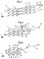
- Figure 1 shows an array of nine fibre-optic cable end faces (pixels) 4 each having a fibre-optic transmission path 6 for carrying optical signals to a corresponding array of APD's 8.
- pixels fibre-optic transmission path 6 for carrying optical signals to a corresponding array of APD's 8.
- APD optical detection and processing of the light source 1
- each APD 8 provides the means for optical detection and processing of the light source 1, each having a corresponding output transmission line 9 for supplying the light information on to a further processing means 10 via input terminals 12.
- the further processing means 10 is then utilised to construct a three-dimensional image of the body illuminated by the light source.
- Each of the fibre-optic transmission lines 6 are of substantially equal length, thereby providing all light source information 1 falling on any of the pixels 4 in phase to the APD's 8.
- FIG. 2 shows an imaging laser-radar having an identical number of pixels 4 to that described in the example shown in figure 1, but distinguished therefrom in that each of said fibre-optic transmission lines 14 carry light source information 1 to a single APD 18.
- the receiver shown in Figure 2 utilises delays 16 in the fibre-optic transmission lines 14 to provide time shifted pulses to the APD 18.
- all nine pixels feed one APD 18.
- the centre pixel 24 has the shortest fibre-optic transmission line 26 for transmitting light source information 1 to the APD 18.
- Each of the remaining surrounding pixels are connected to the APD 18 by fibre-optic transmission lines 14, each having corresponding delays 16, each delay (d1, d2, d3 ... d8) being different and each delay being provided in this example by a different length of fibre.
- This arrangement provides for the light source data 1 from the nine pixels to be multiplexed into the APD 18.
- any one pixel could equally be selected to be that with the shortest time transmission path.
- the 3x3 example in figure 2 provides an arrangement which requires eight less APDs in order to provide the same light source data 1 to an APD for onward processing by the processor unit 20.
- This principle can be scaled to suit various arrays of pixels retaining the same benefits. For example in a 5x5 array it would be possible to utilise one centre pixel surrounded by twenty four further pixels, each utilising delays 16 in their respective optical transmission lines.
- a comparable system in accordance with the receiver as described by figure 2 would use twenty four fewer APD elements.
- Another type of range ambiguity occurs when not all of the pixels in the array capture an optical signal. This may occur for example, when the array is directed towards the edge of the body or target and not all of the pixels receive a reflected pulse.
- the APD 18 will see the pulse from the centre pixel followed by eight sequential pulses from the surrounding pixels. Each pulse will occur at or about 200ns intervals depending on the physical relationship between the plane of the array of pixels and the angle to the light source. Hence, the train of nine pulses will have been detected within about 1.6 ⁇ s (i.e. 8 x 200ns). Assuming a typical imaging at frame rate of 1kHz it will be evident that many more surrounding pixel pulses could be detected in the example given above, where a 1 kHz repetition rate implies a window of 1 millisecond (1000 ⁇ s). The range to an object, regardless of whether it is the centre or a surrounding pixel, can therefore be determined for each pixel and a 3 dimensional image of the illuminated object constructed.
- a further aspect to be taken into account when considering the example in figure 2, is the total length of fibre-optic cable required.
- the first surrounding pixel has an associated 40m fibre, and the last (i.e. 8th) has a 320m fibre.
- the length of fibre required for each 3x3 array using the receiver as described in figure 2 is 1.44 km. If this figure is now applied to a scaled up and representative array size of 24x24 pixels, then utilising one APD per nine pixels results in a requirement for sixty four 3x3 arrangements. Accordingly, the total length of fibre-optic cable required for a 24x24 pixel array would equal 92 km. Using fibres with an outside diameter of 100 ⁇ m and assuming a packing density of 78% (i.e. ⁇ /4), this would result in a fibre-optic volume requirement of 900cc.
- This volume can be further reduced by a factor of four if 50 ⁇ m diameter fibre was utilised. Further reductions in the fibre volume requirement could also be achieved by the use of mirrored end fibres to produce 2-pass 'stub' delay lines. The introduction of such 2-pass stub delay lines could effectively halve the physical length of the fibre-optic transmission lines 14.
- a range ambiguity such as those described above does exist, this may be addressed by using a known range finder.
- the invention may be used to eliminate range ambiguities. This might be done by identifying which pixel transmits which signal to the ADP. This could be done in a variety of different ways, including that described below with respect to Figure 3.
- FIG 3 shows an imaging laser-radar receiver similar to that of Figure 2, but only the fibre-optic transmission cables 14 from three of the pixels are shown for reasons of clarity.
- Each pixel has a fibre-optic cable 14 for carrying light source information to a single APD 18.
- Each of the fibre-optic transmission cables 14 are of a different length as described with respect of Figure 2, but differ from those shown in Figure 2 in that they each have an alternative path 14a.
- the alternative path is a fibre-optic transmission cable having the same or similar characteristics to the original fibre-optic transmission cable 14.
- the alternative path 14a joins up with the original fibre-optic transmission cable 14 prior to arrival at the APD18.
- the alternative path 14a is of a different length to the corresponding portion 14b of the original fibre-optic transmission cable 14.
- the difference in arrival times ⁇ d of the two light pulses from any one pixel at the APD 18 is preferably very small in comparison to the difference in arrival times of light pulses from the different pixels. (e.g. the difference between d1 and d8).
- Each pixel has an alternate path of different length from those of other pixels, so that the difference ⁇ d is different for the two light pulses being carried from each of the pixels. This allows the processor unit 20 to identify which pixel received the reflected light.
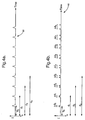
- Figures 4a and 4b help to explain how range ambiguities can be eliminated using the apparatus described with respect to figure 3.
- the range is a function of the time taken for the light pulse to travel to the body or target and back plus the time for the light pulse to travel along the fibre-optic transmission cable 14.
- the pulse train 50 is that which might be received by the APD 18 when the apparatus of Figure 2 is used.
- Time T o is the time at which the first light source data 1 is received by a pixel.
- the delay in the signals reaching the ADP is different for each pixel due to the difference in cable length.
- the pulse train 50 would occur. Any range ambiguity would result in the pulses either being in a different order than expected, or in fewer than a full set of pulses (in this example nine) being received, and the processor will not know which pixels received the light source data and therefore the processor will not know the cable length for those pixels and hence the range of the object.
- the resulting pulse train 52 would occur.
- the difference between signals received from one pixel ⁇ d is different for each pixel ( ⁇ d1, ⁇ d2, etc.) and so each pixel receiving light source data can be identified by the processor. Any range ambiguity resulting in fewer than a full set of pulses being received would not hamper range calculations, as the processor is able to identify the pixel receiving the light source data, and therefore the processor will know the cable length for the pixel and the range of the object can be calculated.
- fibre-optic cables 14a having different characteristics could be used instead for each pixel.
- Figure 5 shows a second embodiment of the invention wherein a different arrangement of fibre-optic delay lines 30, 32, 34, 36, 38, 40, 42 and 44 is provided.
- a pixel 24 hereinafter referred to as a 'master' pixel is connected to an APD 18 via fibre-optic transmission line 28 in a similar manner to that described in figure 2.
- the delay line 30 emanating from 'slave' pixel f1 is connected into the delay line 28 of the master pixel 24.
- Each of the remaining 'slave' pixels f2, f3, Vietnamese,f8 are similarly connected in series, with delay line 32 from pixel f2 being connected into the delay line 30 of pixel f1, and onwards into optical fibre transmission line 28.
- the sequence of connecting the fibre-optic delay line from each associated pixel into its neighbour provides for a delay line structure where for example light signals 1 incident on pixel f8 travel through fibre-optic delay line 44, on through fibre-optic delay line 42 associated with pixel f7, and similarly on through fibre-optic delay line 40 associated with pixel f6 until the signal is finally transmitted to the APD 18 via the master pixel optical fibre transmission line 28.
- Alternative methods by which the delay may be introduced into the optical transmission lines of any of the laser-radar receivers described above in accordance with the present invention also include, but are not limited to, variations in the refractive index of the optical fibre material, and the use of optical fibres of differing materials.
- cut ends 4 of the optical fibres 2 could be coated or covered with or by materials which act as filters, such as but not limited to band pass, high pass or low pass filters, thereby providing for the system to be designed to be responsive to particular ranges of electromagnetic energy wavelengths.
- the invention as described above could alternatively comprise a focal plane array assembly.
- arrays of pixel elements formed into regular square elements i.e. 3x3, 4x4, 5x5 etc.
- This feature should not be construed as limiting the invention to array patterns of regular shapes.
- Arrays in accordance with the invention may comprise pixels formed into regular or irregular or random layouts, be they planar or non-planar (i.e. 2 or 3 dimensional).
- Arrays may also be conformal, in that their application is such that they are required to be integrated into the outer surface such of a vehicle or body.
- array size is not limited to one cluster of pixels. Any number of clusters may be combined to produce an overall array in accordance with the invention. Larger arrays may comprise clusters of pixels of any of the forms described by figures 1, 2 or 3, or in any combination thereof.
- the APD would experience a current which exhibited a step increase each time the APD received an optical signal from a pixel.
- the quality of information obtained from utilising the present invention can be tailored for individual applications, by adjustment to the number of pulses within a given time period, and the duration of those pulses.
Landscapes
- Engineering & Computer Science (AREA)
- Physics & Mathematics (AREA)
- Computer Networks & Wireless Communication (AREA)
- General Physics & Mathematics (AREA)
- Radar, Positioning & Navigation (AREA)
- Remote Sensing (AREA)
- Electromagnetism (AREA)
- Optical Radar Systems And Details Thereof (AREA)
- Investigating Or Analyzing Materials By The Use Of Ultrasonic Waves (AREA)
- Investigating Or Analysing Materials By Optical Means (AREA)
- Burglar Alarm Systems (AREA)
Applications Claiming Priority (3)
| Application Number | Priority Date | Filing Date | Title |
|---|---|---|---|
| GB0024587 | 2000-10-05 | ||
| GBGB0024587.8A GB0024587D0 (en) | 2000-10-05 | 2000-10-05 | Pulse shifted array |
| PCT/GB2001/004375 WO2002029436A1 (en) | 2000-10-05 | 2001-10-01 | Pulse shifted array |
Publications (2)
| Publication Number | Publication Date |
|---|---|
| EP1322974A1 EP1322974A1 (en) | 2003-07-02 |
| EP1322974B1 true EP1322974B1 (en) | 2007-11-07 |
Family
ID=9900844
Family Applications (1)
| Application Number | Title | Priority Date | Filing Date |
|---|---|---|---|
| EP01972268A Expired - Lifetime EP1322974B1 (en) | 2000-10-05 | 2001-10-01 | Pulse shifted array |
Country Status (10)
| Country | Link |
|---|---|
| US (2) | US7095489B2 (enExample) |
| EP (1) | EP1322974B1 (enExample) |
| JP (1) | JP4044435B2 (enExample) |
| AT (1) | ATE377769T1 (enExample) |
| AU (2) | AU9204801A (enExample) |
| CA (1) | CA2424678C (enExample) |
| DE (1) | DE60131289T2 (enExample) |
| ES (1) | ES2294031T3 (enExample) |
| GB (1) | GB0024587D0 (enExample) |
| WO (1) | WO2002029436A1 (enExample) |
Families Citing this family (15)
| Publication number | Priority date | Publication date | Assignee | Title |
|---|---|---|---|---|
| IL155113A0 (en) | 2003-03-27 | 2004-06-20 | Elop Electrooptics Ind Ltd | A method and a system for ranging a scene |
| ES2555124T3 (es) * | 2003-09-26 | 2015-12-29 | Mbda Uk Limited | Sistema óptico de formación de imágenes con líneas ópticas de retardo |
| GB0325785D0 (en) | 2003-11-05 | 2004-08-04 | Mbda Uk Ltd | Detection of an electromagnetic signal |
| WO2005052632A1 (en) | 2003-11-20 | 2005-06-09 | Mbda Uk Limited | Signal processing system |
| US7079228B2 (en) * | 2004-04-15 | 2006-07-18 | Rosemount Aerospace Inc. | Combined laser altimeter and ground velocity measurement apparatus |
| US7633670B2 (en) | 2004-07-16 | 2009-12-15 | The Ohio State University | Methods, systems, and devices for steering optical beams |
| US7430347B2 (en) | 2004-07-16 | 2008-09-30 | The Ohio State University | Methods, systems, and apparatuses for optically generating time delays in signals |
| US20060034567A1 (en) | 2004-07-16 | 2006-02-16 | Anderson Betty L | Optical beam combiner |
| US7375804B2 (en) * | 2005-03-01 | 2008-05-20 | Lockheed Martin Corporation | Single detector receiver for multi-beam LADAR systems |
| US7630598B2 (en) | 2006-05-10 | 2009-12-08 | The Ohio State University | Apparatus and method for providing an optical cross-connect |
| US7911671B2 (en) | 2006-05-10 | 2011-03-22 | The Ohio State University | Apparatus and method for providing true time delay in optical signals using a Fourier cell |
| EP2228619A1 (en) * | 2009-03-12 | 2010-09-15 | MBDA UK Limited | Optical proximity fuze |
| EP2318803B1 (en) * | 2008-08-08 | 2012-10-31 | MBDA UK Limited | Optical proximity fuze |
| JP2018524043A (ja) * | 2015-05-19 | 2018-08-30 | プロトンブイディーエー インコーポレイテッド | 陽子療法の最適化のための陽子撮像システム |
| CN109458957A (zh) * | 2018-12-27 | 2019-03-12 | 中国电子科技集团公司第三十四研究所 | 一种阵列光纤光镊光纤芯间平行度测试方法 |
Family Cites Families (15)
| Publication number | Priority date | Publication date | Assignee | Title |
|---|---|---|---|---|
| US3991318A (en) * | 1973-09-28 | 1976-11-09 | Bell Telephone Laboratories, Incorporated | Optical detection systems utilizing organ arrays of optical fibers |
| GB1525463A (en) | 1975-11-10 | 1978-09-20 | Emi Ltd | Radiographic apparatus |
| US4164373A (en) * | 1978-01-12 | 1979-08-14 | The United States Of America As Represented By The United States Department Of Energy | Spectrometer employing optical fiber time delays for frequency resolution |
| FR2476326A1 (fr) * | 1980-02-20 | 1981-08-21 | Cilas | Dispositif pour determiner la position angulaire d'une cible eclairee par des impulsions lumineuses |
| US4380391A (en) * | 1980-09-30 | 1983-04-19 | The United States Of America As Represented By The Secretary Of The Army | Short pulse CO2 laser for ranging and target identification |
| GB2112244B (en) | 1981-12-18 | 1985-06-19 | Pilkington Perkin Elmer Ltd | Improvements in or relating to monitoring apparatus |
| EP0283538B1 (de) | 1987-03-26 | 1990-08-16 | Messerschmitt-Bölkow-Blohm Gesellschaft mit beschränkter Haftung | Detektorvorrichtung |
| DE3833634A1 (de) * | 1988-10-04 | 1990-04-12 | Messerschmitt Boelkow Blohm | Laserwarnsensor |
| JPH04348258A (ja) | 1991-05-27 | 1992-12-03 | Kowa Co | 多チャンネル光学測定装置 |
| US5760852A (en) * | 1995-11-03 | 1998-06-02 | Hughes Electronics Corporation | Laser-hardened eye protection goggles |
| US5953110A (en) * | 1998-04-23 | 1999-09-14 | H.N. Burns Engineering Corporation | Multichannel laser radar |
| US6163372A (en) | 1999-02-09 | 2000-12-19 | Marconi Aerospace Defense Systems Inc. | Fiber optic laser detection and ranging system |
| US6246822B1 (en) | 1999-05-18 | 2001-06-12 | The Boeing Company | Fiber-coupled receiver and associated method |
| JP2001201573A (ja) * | 2000-01-20 | 2001-07-27 | Mitsubishi Electric Corp | コヒーレントレーザレーダ装置および目標測定方法 |
| IL136036A (en) | 2000-05-09 | 2004-07-25 | Elop Electrooptics Ind Ltd | Method and system for visualizing multiple elements of an image |
-
2000
- 2000-10-05 GB GBGB0024587.8A patent/GB0024587D0/en not_active Ceased
-
2001
- 2001-10-01 EP EP01972268A patent/EP1322974B1/en not_active Expired - Lifetime
- 2001-10-01 ES ES01972268T patent/ES2294031T3/es not_active Expired - Lifetime
- 2001-10-01 DE DE60131289T patent/DE60131289T2/de not_active Expired - Lifetime
- 2001-10-01 AT AT01972268T patent/ATE377769T1/de not_active IP Right Cessation
- 2001-10-01 AU AU9204801A patent/AU9204801A/xx active Pending
- 2001-10-01 CA CA2424678A patent/CA2424678C/en not_active Expired - Fee Related
- 2001-10-01 WO PCT/GB2001/004375 patent/WO2002029436A1/en not_active Ceased
- 2001-10-01 US US10/381,139 patent/US7095489B2/en not_active Expired - Fee Related
- 2001-10-01 AU AU2001292048A patent/AU2001292048B2/en not_active Ceased
- 2001-10-01 JP JP2002532958A patent/JP4044435B2/ja not_active Expired - Fee Related
-
2005
- 2005-10-26 US US11/258,243 patent/US7126675B2/en not_active Expired - Fee Related
Also Published As
| Publication number | Publication date |
|---|---|
| CA2424678A1 (en) | 2002-04-11 |
| US7126675B2 (en) | 2006-10-24 |
| JP2004510988A (ja) | 2004-04-08 |
| CA2424678C (en) | 2011-09-20 |
| US20030179367A1 (en) | 2003-09-25 |
| ES2294031T3 (es) | 2008-04-01 |
| DE60131289T2 (de) | 2008-11-27 |
| AU9204801A (en) | 2002-04-15 |
| DE60131289D1 (de) | 2007-12-20 |
| EP1322974A1 (en) | 2003-07-02 |
| JP4044435B2 (ja) | 2008-02-06 |
| GB0024587D0 (en) | 2001-08-15 |
| ATE377769T1 (de) | 2007-11-15 |
| AU2001292048B2 (en) | 2006-01-19 |
| WO2002029436A1 (en) | 2002-04-11 |
| US7095489B2 (en) | 2006-08-22 |
| US20060082757A1 (en) | 2006-04-20 |
Similar Documents
| Publication | Publication Date | Title |
|---|---|---|
| EP1322974B1 (en) | Pulse shifted array | |
| AU2001292048A1 (en) | Pulse shifted array | |
| CN112292608B (zh) | 用于lidar系统的二维操纵系统 | |
| EP1680687B1 (en) | Detection of an electromagnetic signal | |
| US4634272A (en) | Optical radar system with an array of photoelectric sensors | |
| US4949074A (en) | Method of intrusion detection | |
| US9429651B2 (en) | Method of monitoring an area | |
| US9048609B2 (en) | Laser emitter module and laser detecting system to which the laser emitter module is applied | |
| US5953110A (en) | Multichannel laser radar | |
| US4903009A (en) | Intrusion detection device | |
| US20060197936A1 (en) | Single detector receiver for multi-beam LADAR systems | |
| US20230135132A1 (en) | Methods and Systems for Dithering Active Sensor Pulse Emissions | |
| CN113272676A (zh) | 用于映射回射器的方法和系统 | |
| US20150268332A1 (en) | Object detection device and remote sensing apparatus | |
| WO2023018945A1 (en) | Coaxial lidar system using a diffractive waveguide | |
| EP0867018B1 (fr) | Dispositif de detection de presence et de sens de passage de mobiles et de personnes en vue du comptage | |
| EP1154639A1 (en) | A method and system for multi-pixel imaging | |
| US7087886B2 (en) | Method and a system for multi-pixel ranging of a scene | |
| US11914076B2 (en) | Solid state pulse steering in LiDAR systems | |
| JPH06317656A (ja) | 2次元受光回路素子及び光情報入力処理装置 | |
| EP4375702A1 (en) | Device for scanning fmcw lidar range measurement | |
| Krill et al. | Multifunction array lidar network for intruder detection, tracking, and identification | |
| WO2004086088A1 (en) | A method and a system for ranging a scene | |
| CN117214865A (zh) | 一种镜头阵列激光雷达 |
Legal Events
| Date | Code | Title | Description |
|---|---|---|---|
| PUAI | Public reference made under article 153(3) epc to a published international application that has entered the european phase |
Free format text: ORIGINAL CODE: 0009012 |
|
| 17P | Request for examination filed |
Effective date: 20030320 |
|
| AK | Designated contracting states |
Designated state(s): AT BE CH CY DE DK ES FI FR GB GR IE IT LI LU MC NL PT SE TR |
|
| AX | Request for extension of the european patent |
Extension state: AL LT LV MK RO SI |
|
| GRAP | Despatch of communication of intention to grant a patent |
Free format text: ORIGINAL CODE: EPIDOSNIGR1 |
|
| GRAS | Grant fee paid |
Free format text: ORIGINAL CODE: EPIDOSNIGR3 |
|
| 17Q | First examination report despatched |
Effective date: 20040826 |
|
| GRAJ | Information related to disapproval of communication of intention to grant by the applicant or resumption of examination proceedings by the epo deleted |
Free format text: ORIGINAL CODE: EPIDOSDIGR1 |
|
| GRAP | Despatch of communication of intention to grant a patent |
Free format text: ORIGINAL CODE: EPIDOSNIGR1 |
|
| GRAS | Grant fee paid |
Free format text: ORIGINAL CODE: EPIDOSNIGR3 |
|
| GRAA | (expected) grant |
Free format text: ORIGINAL CODE: 0009210 |
|
| AK | Designated contracting states |
Kind code of ref document: B1 Designated state(s): AT BE CH CY DE DK ES FI FR GB GR IE IT LI LU MC NL PT SE TR |
|
| REG | Reference to a national code |
Ref country code: GB Ref legal event code: FG4D |
|
| REG | Reference to a national code |
Ref country code: IE Ref legal event code: FG4D |
|
| REG | Reference to a national code |
Ref country code: CH Ref legal event code: EP |
|
| REF | Corresponds to: |
Ref document number: 60131289 Country of ref document: DE Date of ref document: 20071220 Kind code of ref document: P |
|
| REG | Reference to a national code |
Ref country code: SE Ref legal event code: TRGR |
|
| REG | Reference to a national code |
Ref country code: ES Ref legal event code: FG2A Ref document number: 2294031 Country of ref document: ES Kind code of ref document: T3 |
|
| ET | Fr: translation filed | ||
| PG25 | Lapsed in a contracting state [announced via postgrant information from national office to epo] |
Ref country code: AT Free format text: LAPSE BECAUSE OF FAILURE TO SUBMIT A TRANSLATION OF THE DESCRIPTION OR TO PAY THE FEE WITHIN THE PRESCRIBED TIME-LIMIT Effective date: 20071107 |
|
| PG25 | Lapsed in a contracting state [announced via postgrant information from national office to epo] |
Ref country code: DK Free format text: LAPSE BECAUSE OF FAILURE TO SUBMIT A TRANSLATION OF THE DESCRIPTION OR TO PAY THE FEE WITHIN THE PRESCRIBED TIME-LIMIT Effective date: 20071107 |
|
| PG25 | Lapsed in a contracting state [announced via postgrant information from national office to epo] |
Ref country code: BE Free format text: LAPSE BECAUSE OF FAILURE TO SUBMIT A TRANSLATION OF THE DESCRIPTION OR TO PAY THE FEE WITHIN THE PRESCRIBED TIME-LIMIT Effective date: 20071107 |
|
| PLBE | No opposition filed within time limit |
Free format text: ORIGINAL CODE: 0009261 |
|
| STAA | Information on the status of an ep patent application or granted ep patent |
Free format text: STATUS: NO OPPOSITION FILED WITHIN TIME LIMIT |
|
| PG25 | Lapsed in a contracting state [announced via postgrant information from national office to epo] |
Ref country code: PT Free format text: LAPSE BECAUSE OF FAILURE TO SUBMIT A TRANSLATION OF THE DESCRIPTION OR TO PAY THE FEE WITHIN THE PRESCRIBED TIME-LIMIT Effective date: 20080407 |
|
| 26N | No opposition filed |
Effective date: 20080808 |
|
| PG25 | Lapsed in a contracting state [announced via postgrant information from national office to epo] |
Ref country code: GR Free format text: LAPSE BECAUSE OF FAILURE TO SUBMIT A TRANSLATION OF THE DESCRIPTION OR TO PAY THE FEE WITHIN THE PRESCRIBED TIME-LIMIT Effective date: 20080208 |
|
| PG25 | Lapsed in a contracting state [announced via postgrant information from national office to epo] |
Ref country code: FI Free format text: LAPSE BECAUSE OF FAILURE TO SUBMIT A TRANSLATION OF THE DESCRIPTION OR TO PAY THE FEE WITHIN THE PRESCRIBED TIME-LIMIT Effective date: 20071107 |
|
| PG25 | Lapsed in a contracting state [announced via postgrant information from national office to epo] |
Ref country code: MC Free format text: LAPSE BECAUSE OF NON-PAYMENT OF DUE FEES Effective date: 20081031 |
|
| PG25 | Lapsed in a contracting state [announced via postgrant information from national office to epo] |
Ref country code: CY Free format text: LAPSE BECAUSE OF FAILURE TO SUBMIT A TRANSLATION OF THE DESCRIPTION OR TO PAY THE FEE WITHIN THE PRESCRIBED TIME-LIMIT Effective date: 20071107 |
|
| PG25 | Lapsed in a contracting state [announced via postgrant information from national office to epo] |
Ref country code: IE Free format text: LAPSE BECAUSE OF NON-PAYMENT OF DUE FEES Effective date: 20081001 |
|
| PG25 | Lapsed in a contracting state [announced via postgrant information from national office to epo] |
Ref country code: LU Free format text: LAPSE BECAUSE OF NON-PAYMENT OF DUE FEES Effective date: 20081001 |
|
| PG25 | Lapsed in a contracting state [announced via postgrant information from national office to epo] |
Ref country code: TR Free format text: LAPSE BECAUSE OF FAILURE TO SUBMIT A TRANSLATION OF THE DESCRIPTION OR TO PAY THE FEE WITHIN THE PRESCRIBED TIME-LIMIT Effective date: 20071107 |
|
| REG | Reference to a national code |
Ref country code: FR Ref legal event code: PLFP Year of fee payment: 15 |
|
| REG | Reference to a national code |
Ref country code: FR Ref legal event code: PLFP Year of fee payment: 16 |
|
| PGFP | Annual fee paid to national office [announced via postgrant information from national office to epo] |
Ref country code: FR Payment date: 20161020 Year of fee payment: 16 Ref country code: CH Payment date: 20161020 Year of fee payment: 16 Ref country code: NL Payment date: 20161019 Year of fee payment: 16 Ref country code: GB Payment date: 20161020 Year of fee payment: 16 Ref country code: DE Payment date: 20161020 Year of fee payment: 16 |
|
| PGFP | Annual fee paid to national office [announced via postgrant information from national office to epo] |
Ref country code: SE Payment date: 20161019 Year of fee payment: 16 Ref country code: ES Payment date: 20161011 Year of fee payment: 16 |
|
| PGFP | Annual fee paid to national office [announced via postgrant information from national office to epo] |
Ref country code: IT Payment date: 20171025 Year of fee payment: 17 |
|
| REG | Reference to a national code |
Ref country code: DE Ref legal event code: R119 Ref document number: 60131289 Country of ref document: DE |
|
| REG | Reference to a national code |
Ref country code: SE Ref legal event code: EUG |
|
| REG | Reference to a national code |
Ref country code: CH Ref legal event code: PL |
|
| REG | Reference to a national code |
Ref country code: NL Ref legal event code: MM Effective date: 20171101 |
|
| GBPC | Gb: european patent ceased through non-payment of renewal fee |
Effective date: 20171001 |
|
| REG | Reference to a national code |
Ref country code: FR Ref legal event code: ST Effective date: 20180629 |
|
| PG25 | Lapsed in a contracting state [announced via postgrant information from national office to epo] |
Ref country code: LI Free format text: LAPSE BECAUSE OF NON-PAYMENT OF DUE FEES Effective date: 20171031 Ref country code: NL Free format text: LAPSE BECAUSE OF NON-PAYMENT OF DUE FEES Effective date: 20171101 Ref country code: CH Free format text: LAPSE BECAUSE OF NON-PAYMENT OF DUE FEES Effective date: 20171031 Ref country code: DE Free format text: LAPSE BECAUSE OF NON-PAYMENT OF DUE FEES Effective date: 20180501 Ref country code: GB Free format text: LAPSE BECAUSE OF NON-PAYMENT OF DUE FEES Effective date: 20171001 |
|
| PG25 | Lapsed in a contracting state [announced via postgrant information from national office to epo] |
Ref country code: SE Free format text: LAPSE BECAUSE OF NON-PAYMENT OF DUE FEES Effective date: 20171002 Ref country code: FR Free format text: LAPSE BECAUSE OF NON-PAYMENT OF DUE FEES Effective date: 20171031 |
|
| REG | Reference to a national code |
Ref country code: ES Ref legal event code: FD2A Effective date: 20181017 |
|
| PG25 | Lapsed in a contracting state [announced via postgrant information from national office to epo] |
Ref country code: ES Free format text: LAPSE BECAUSE OF NON-PAYMENT OF DUE FEES Effective date: 20171002 |
|
| PG25 | Lapsed in a contracting state [announced via postgrant information from national office to epo] |
Ref country code: IT Free format text: LAPSE BECAUSE OF NON-PAYMENT OF DUE FEES Effective date: 20181001 |