EP1322470B1 - Vorrichtung zur verarbeitung von substraten mit aufeinandergepressten vorratsrollen - Google Patents
Vorrichtung zur verarbeitung von substraten mit aufeinandergepressten vorratsrollen Download PDFInfo
- Publication number
- EP1322470B1 EP1322470B1 EP01975615A EP01975615A EP1322470B1 EP 1322470 B1 EP1322470 B1 EP 1322470B1 EP 01975615 A EP01975615 A EP 01975615A EP 01975615 A EP01975615 A EP 01975615A EP 1322470 B1 EP1322470 B1 EP 1322470B1
- Authority
- EP
- European Patent Office
- Prior art keywords
- supply
- substrate
- supply roll
- processing apparatus
- rolls
- Prior art date
- Legal status (The legal status is an assumption and is not a legal conclusion. Google has not performed a legal analysis and makes no representation as to the accuracy of the status listed.)
- Expired - Lifetime
Links
Images


Classifications
-
- B—PERFORMING OPERATIONS; TRANSPORTING
- B32—LAYERED PRODUCTS
- B32B—LAYERED PRODUCTS, i.e. PRODUCTS BUILT-UP OF STRATA OF FLAT OR NON-FLAT, e.g. CELLULAR OR HONEYCOMB, FORM
- B32B37/00—Methods or apparatus for laminating, e.g. by curing or by ultrasonic bonding
- B32B37/14—Methods or apparatus for laminating, e.g. by curing or by ultrasonic bonding characterised by the properties of the layers
- B32B37/16—Methods or apparatus for laminating, e.g. by curing or by ultrasonic bonding characterised by the properties of the layers with all layers existing as coherent layers before laminating
- B32B37/22—Methods or apparatus for laminating, e.g. by curing or by ultrasonic bonding characterised by the properties of the layers with all layers existing as coherent layers before laminating involving the assembly of both discrete and continuous layers
- B32B37/223—One or more of the layers being plastic
- B32B37/226—Laminating sheets, panels or inserts between two continuous plastic layers
-
- B—PERFORMING OPERATIONS; TRANSPORTING
- B32—LAYERED PRODUCTS
- B32B—LAYERED PRODUCTS, i.e. PRODUCTS BUILT-UP OF STRATA OF FLAT OR NON-FLAT, e.g. CELLULAR OR HONEYCOMB, FORM
- B32B2307/00—Properties of the layers or laminate
- B32B2307/20—Properties of the layers or laminate having particular electrical or magnetic properties, e.g. piezoelectric
- B32B2307/208—Magnetic, paramagnetic
-
- Y—GENERAL TAGGING OF NEW TECHNOLOGICAL DEVELOPMENTS; GENERAL TAGGING OF CROSS-SECTIONAL TECHNOLOGIES SPANNING OVER SEVERAL SECTIONS OF THE IPC; TECHNICAL SUBJECTS COVERED BY FORMER USPC CROSS-REFERENCE ART COLLECTIONS [XRACs] AND DIGESTS
- Y10—TECHNICAL SUBJECTS COVERED BY FORMER USPC
- Y10T—TECHNICAL SUBJECTS COVERED BY FORMER US CLASSIFICATION
- Y10T156/00—Adhesive bonding and miscellaneous chemical manufacture
- Y10T156/10—Methods of surface bonding and/or assembly therefor
- Y10T156/1089—Methods of surface bonding and/or assembly therefor of discrete laminae to single face of additional lamina
- Y10T156/1092—All laminae planar and face to face
- Y10T156/1093—All laminae planar and face to face with covering of discrete laminae with additional lamina
- Y10T156/1095—Opposed laminae are running length webs
-
- Y—GENERAL TAGGING OF NEW TECHNOLOGICAL DEVELOPMENTS; GENERAL TAGGING OF CROSS-SECTIONAL TECHNOLOGIES SPANNING OVER SEVERAL SECTIONS OF THE IPC; TECHNICAL SUBJECTS COVERED BY FORMER USPC CROSS-REFERENCE ART COLLECTIONS [XRACs] AND DIGESTS
- Y10—TECHNICAL SUBJECTS COVERED BY FORMER USPC
- Y10T—TECHNICAL SUBJECTS COVERED BY FORMER US CLASSIFICATION
- Y10T156/00—Adhesive bonding and miscellaneous chemical manufacture
- Y10T156/17—Surface bonding means and/or assemblymeans with work feeding or handling means
- Y10T156/1702—For plural parts or plural areas of single part
- Y10T156/1712—Indefinite or running length work
- Y10T156/1741—Progressive continuous bonding press [e.g., roll couples]
Definitions
- the present invention relates to a substrate processing apparatus for performing a processing operation on a selected substrate. More specifically, the present invention relates to a substrate processing apparatus that has a pair of pressed together supply rolls for applying pressure to perform the processing operation.
- US Patent No. 5,961,779 discloses a laminating and adhesive transfer apparatus.
- the apparatus has a frame and first and second supply rolls.
- the first and second supply rolls are rotatively secured in a cartridge.
- First and second nip rollers are provided to apply pressure to the master and stock material to perform lamination or adhesive transfer.
- nip rollers are used to apply the pressure required to perform a master processing operation. More specifically, the devices disclosed in these prior art patents are designed to apply pressure with their nip rollers to adhere pressure-sensitive adhesive from one or both of the supply materials to the selected substrate being processed.
- the processing operations disclosed in these patents may include an adhesive transfer operation wherein the adhesive is transferred to only one side of the selected substrate to create a label or sticker; a laminating operation wherein each supply material has a layer of adhesive and the supply materials are adhered to both sides of selected substrate; or a combination laminating/adhesive transfer operation wherein one of the supply materials is adhesively bonded to one side of the selected substrate and the adhesive on the other supply material is transferred to the other side of the selected substrate.
- nip rollers in the types of devices shown in these prior art patents is well-known for applying the requisite pressure to bond the pressure-sensitive adhesive on one or both of the supply materials to the substrate being processed.
- the nip rollers represent a significant amount of both the cost and weight of the device.
- the nip rollers add to the overall size and manufacturing complexity of the device. The nip rollers must be pressed together with the correct amount of force and also must be properly aligned to ensure a smooth, efficient processing operation.
- the apparatus comprises a frame and a first supply roll rotatably mounted to the frame, the first supply roll comprising a first supply substrate having a first surface and a second surface.
- the first supply substrate is wound about the first supply roll such that the first surface thereof faces radially outward with respect to the first supply roll.
- a second supply roll is rotatably mounted to the frame.
- the second supply roll comprises a second supply substrate having a first surface and a second surface, the second supply substrate being wound about the second supply roll such that the first surface thereof faces radially outward with respect to the second supply roll.
- the first and second supply rolls are relatively movable toward one another to engage the first surfaces of the first and second supply substrates with one another.
- At least the first surface of the first supply substrate has a layer of pressure-sensitive adhesive disposed thereon.
- the first surface of the second supply substrate may also have a layer of adhesive disposed thereon, depending on the type of processing operation to be performed.
- the apparatus of the invention may be configured for the processing operation to be a laminating operation as the processing operation, wherein the first supply substrate and the second supply substrate are both transparent laminating films and wherein the first surface of the second supply substrate also has a layer of adhesive disposed thereon.
- the apparatus may also be configured for the processing operation to be an adhesive transfer operation wherein the first supply substrate is a release liner and wherein the second supply substrate is a mask substrate devoid of adhesive.
- the apparatus according to the invention may be configured for the processing operation to be a combination laminating/adhesive transfer operation as wherein the first supply substrate is a release liner and wherein the second supply substrate is a transparent laminating film having a layer of adhesive disposed on the first surface thereof.
- the apparatus of the invention may be configured for the processing operation to be a magnet making operation wherein the first supply substrate is a flexible magnet substrate and wherein the second supply substrate is a mask substrate devoid of adhesive while wound on the second supply roll.
- the mask substrate will cover any excess portions of the adhesive on the release liner exposed around a periphery of the selected substrate during the processing operation. It is to be understood that these specific types of processing operations are intended to be illustrative and non-limiting. The invention is intended to encompass any and all types of processing operations wherein adhesive bonding is affected between some or all of the substrates being processed.
- the apparatus of the invention further comprises biasing structure biasing the first and second supply rolls towards one another such that the first surfaces of the first and second supply substrates are pressed into engagement with one another to enable performance of a processing operation wherein (a) the selected substrate is advanced in a feeding direction between the first and second supply rolls so that the pressed engagement of the supply rolls presses the first surfaces of the first and second supply substrates against opposing sides of the selected substrate so as to affect adhesive bonding between the substrates, and (b) the portions of the first and second supply substrates pressed against the selected substrate are unwound from the first and second supply rolls and advanced together with the selected substrate.
- the biasing structure continues to bias the first and second supply rolls towards one another as the first and second supply substrates are depleted from the supply rolls thereby maintain the pressed engagement of the supply rolls.
- the component and manufacturing costs associated with nip rollers are eliminated, thereby reducing the overall cost of the apparatus. Also, the weight and overall size of the processing apparatus may be reduced, if desired, by the elimination of the nip rollers.
- the method comprises: providing a rotatable first supply roll and providing a rotatable second supply roll.
- the first supply roll comprises a first supply substrate having a first surface and a second surface.
- the first surface has a layer of pressure-sensitive adhesive disposed thereon and the first supply substrate is wound about the first supply roll such that the first surface thereof and the adhesive layer face radially outward with respect to the first supply roll.
- the second supply roll comprises a second supply substrate having a first surface and a second surface.
- the second supply substrate is wound about the second supply roll such that the first surface thereof faces radially outward with respect to the second supply roll.
- the method further comprises pressing the first and second supply rolls together such that the first surfaces of the first and second supply substrates are pressed into engagement with one another. While the first and second supply rolls are pressed together, the selected substrate is advanced between the supply rolls so that (a) the pressed engagement of the supply rolls presses the first surfaces against the first and second supply substrates against the opposite sides of the selected substrate so as to cause said adhesive to bond to the selected substrate and (b) the portion of the first and second supply substrates pressed against the selected substrate and advanced together with the selected substrate.
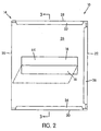
- Fig. 1 shows a substrate processing apparatus, generally indicated at 10, for performing a processing operation on a selected substrate 12.
- the selected substrate 12 may be any type of substrate desired to be processed, including but not limited to photographs, business cards, label stock, price tags, magazine cut-outs, name tags, etc.
- the apparatus 10 may be of any suitable size.
- the apparatus 10 illustrated is of a hand-held size that can be manually grasped and handled in one hand.
- the apparatus 10 comprises a frame 14, a first supply roll 16, a second supply roll 18, and biasing structure, generally indicated at 19.
- the frame 14 in the illustrated embodiment is constructed of cardboard folded into a box shape having two sidewalls 20, 22, a feed sidewall 24, a discharge sidewall 26, a top wall 28, and a bottom wall 30.
- the top wall 28, the bottom wall 30, and the sidewall 22 each have a flap 32, 34, 36, respectively, at the free ends thereof. These flaps 32, 34, 36 are folded around and adhered, stapled or otherwise fixed to the discharge sidewall 26 to secure the frame 14 together.
- the frame 14 may be formed from a single piece of plastic with living hinges.
- the plastic frame would be folded about the living hinges in a manner similar to the cardboard and heat-staked, glued, snap fit or otherwise fixed together for security.
- both the cardboard and the plastic constitute a foldable material.
- the broad principles of the present invention are not limited to the use of a frame 14 made from foldable material.
- the principles of the present invention may be practiced in a frame made of molded rigid plastic or metal.
- the foldable frame is preferred for cost savings purposes.
- the first supply roll 16 comprises a core 38 and a first supply substrate 40 wound on the core 38.
- a pair of plastic supply roll supports 42, 44 are received inside the frame 14 adjacent the bottom wall 30 and sidewalls 20, 22 on opposite sides of the first supply roll 16.
- Each of the supports 42, 44 has a semi-circular recess 46, 48 and the opposing ends of the core 38 are cradled within these recesses 46, 48 to hold the supply roll 16.
- These supply roll supports 42, 44 comprise a first supply roll support structure.
- the second supply roll 18 comprises a core 50 and a second supply substrate 52 wound about the core 50.
- a pair of second supply roll supports are secured by adhesive or threading to the opposing ends of the core 50.
- the supports 54, 56 may be loosely received on the ends of the core 50.
- the supply roll 18 and supports 54, 56 are disposed within the frame 14 with the laterally outer surfaces of the supports 54, 56 slidably engaging the interior surfaces of sidewalls 20, 22, respectively.
- These supply roll supports 54, 56 comprise a second supply roll support structure.
- the cores 38, 50 and supply roll supports 42, 44, 54, 56 may be eliminated in the practice of the invention. These features are preferred to ensure that the supply rolls 16, 18 remain aligned and do not become displaced with respect to one another in the direction extending between the feed and discharge sidewalls 24, 26.
- first supply roll support structure i.e. supply roll supports 42, 44
- second supply roll support structure i.e. supply roll supports 54, 56
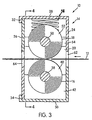
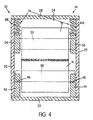
- the biasing structure 19 in the embodiment illustrated in Figs. 3 and 4 is in the form of a pair of ellipsoid coil springs 58, 60. These springs 58, 60 are positioned between the top wall 28 of the frame 14 and the second supply roll supports 54, 56, respectively.
- This biasing structure 19 biases the second supply roll 18 towards the first supply roll 16 so that the radially outermost portions of the supply substrates 40, 52 are pressed into engagement with one another in a manner similar to conventional nip rollers. Further, the biasing structure 19 continues to bias the supply rolls 16, 18 towards one another as the supply substrates 40, 52 are depleted therefrom to thereby maintain the pressed engagement of the supply rolls 16, 18. This keeps the supply rolls 16, 18 pressed together as their diameters are reduced due to depletion of the supply substrates 40, 52.
- any suitable biasing structure may be used for biasing the supply rolls 16, 18 into pressed engagement with one another.
- a single spring may be used, a plurality of springs engaged between the frame walls and each of the supply rolls 16, 18 may be used, or springs engaged between the two supply rolls 16, 18 without engaging the frame 14 may be used.
- resilient material such as resilient rubber members, may be used in place of the spring(s).
- elastic rubber bands connected between the ends of the two cores 38, 50 may be used to bias the supply rolls 16, 18 together into pressed engagement.
- Each of the supply substrates 40, 52 has a first surface and a second surface opposite the first surface. These supply substrates 40, 52 are wound about their respective cores 38, 50 so that the first surfaces thereof face radially outwardly with respect to their supply rolls 16, 18 and the second surfaces face radially inwardly with respect to their supply rolls 16, 18.
- the first surface of the first supply substrate 40 is coated with a layer of pressure-sensitive adhesive. Because the first surface of the first supply substrate 40 faces radially outwardly, the adhesive will likewise face radially outwardly.
- both the supply substrates 40, 52 would be transparent films and the second supply substrate 52 would also have its first surface coated with a pressure-sensitive adhesive and its second surface treated with a release material, such as silicone or wax.
- the second surface of the first supply substrate 40 also has its second surface coated with a release material.
- the adhesive on the second supply substrate's first surface faces radially outwardly.
- the release material on the second surfaces of the supply substrates 40, 52 prevents that adhesive from bonding thereto while wound on the supply rolls 16, 18.
- a release liner could be wound up with both of the supply substrates 40, 52 to prevent the adhesive on the first surface of each substrate 40, 52 from sticking to the second surface.
- the first supply substrate 40 would be a differential release liner coated with release material on both its first and second surfaces.
- the release material on the second surface will prevent the adhesive from bonding thereto and the release material on the first surface will allow the pressure-sensitive adhesive thereon to transfer to the selected substrate without remaining bonded to the first surface.
- the second supply substrate 52 would be a mask substrate that carries no adhesive.
- the first surface of the mask substrate may be left untreated or, alternatively, it may be treated with a release material to prevent adherence of the adhesive on the first supply substrate 40 thereto. The role of the mask substrate will be explained hereinbelow with respect to the operation of the apparatus 10.
- the first supply substrate 40 would be a differential release liner as described above for a normal adhesive transfer operation.
- the second supply substrate 52 would be a transparent film having its first surface coated with a pressure-sensitive adhesive and its second surface coated with a release material as described above for a normal laminating operation.
- the second supply substrate 52 (the transparent film) is adhered to one surface of the selected substrate, and the pressure sensitive adhesive on the first supply substrate 40 (the release liner) is adhered to the other surface of the selected substrate 12.
- the supply substrates 40, 52 are trimmed around the periphery of the selected substrate 12 and the release liner is peeled back to expose the adhesive, thus providing a selected substrate 12 that is adherable like a label, but protected on one side by a laminating film.
- the first supply substrate 40 would be made from a magnetized material, as in U.S. Published Application No. 2030165652.
- the second supply substrate 52 would be a mask substrate as discussed above with respect to the normal adhesive transfer operation.
- Fig. 5 shows another embodiment of the substrate processing apparatus 10.
- the apparatus 10 includes a frame 100 and first and second supply rolls 102,104.
- the supply rolls 102, 104 are mounted between first and second supply roll supports 106, 108.
- the first and second supply roll supports 106, 108 are upstanding and situated at respective opposite ends of the supply rolls 102, 104.
- the supply rolls 102,104 are positioned parallel and adjacent one another and are retained in this orientation by the supply roll supports 106, 108.
- First and second supply rolls 102, 104 include respective first and second supply substrates 110,112, which are similar to supply substrates 40, 52 described above.
- each of the first and second supply roll supports 106, 108 includes an longitudinally extending (relative to the supply rolls 102, 104) elongated opening 114.
- the openings 114 are elongate in a pressing direction, parallel to a plane containing longitudinal axes of both supply rolls 102, 104.
- the pressing direction is generally vertical, however it is contemplated that the pressing direction may be other than vertical, as will be discussed in further detail below.
- a portion of the supply roll supports 106, 108 may be formed to provide a support surface engaging structure 115. As shown in Fig. 5, a lower portion of the supply roll supports 106, 108 may extend laterally outwardly (relative to the supply roll supports 106, 108) to provide the support surface engaging structure 115. With this configuration, the apparatus 10 may stably engage the support surface, provided, for example, by a table or desk.
- the first and second supply rolls 102, 104 include respective cores 116, 118 on which the first and second supply substrates 110, 112 may be wound. As shown, it is preferable for the cores 116, 118 to extend past the longitudinal extent of the wound supply substrates 110, 112. In other words, opposite longitudinal end portions of each supply roll 102, 104 are formed by respective end portions of associated cores 116, 118. As shown in Fig, 5, end portions I20, 122 of cores 116, 118, respectively, extend through the opening 114 in the first supply roll support 106, while end portions 124, 126 of cores 116, 118, respectively, extend through the opening 114 in the second supply roll support 108.
- a width of the openings 114 may be generally equal to or slightly larger than a diameter of the cores 116, 118. As such, each of the cores 116, 118 is slidable within the openings 114 of the supply roll supports 106, 108.
- a biasing structure serves to bias the first and second supply rolls 102, 104 toward each other.
- the biasing structure 130 may be in the form of a pair of coiled extension springs 132 connectable between respective end portions (120-126) of cores 116, 118. It is noted that the biasing structure 130 may be in the form of other resilient elements, including other types of springs and elastomeric members. It is also noted that the biasing structure 130 may bias each of the cores 116, 118 toward an opposite end of the supply roll supports 106, 108, thereby pressing the supply rolls 102, 104 together, as shown in Fig. 5.
- the biasing structure 130 also includes core mounting structures 134, one of which is disposed on each end portion 120, 122, 124, and 126 of each core 116, 118.
- the core mounting structures 134 are rotatably mounted to the respective end portions (122-126), so that as the supply rolls 102, 104 rotate, the core mounting structures 134 are able to maintain a generally constant rotational orientation relative to the supply rolls 102, 104.
- each of the core mounting structures 134 includes a connecting portion 136 extending radially outwardly therefrom.
- the connecting portions 136 include connecting structures 138, which are connectable with respective ends of springs 132. Shown in Fig. 5, the connecting structures 138 may be provided by openings within respective connecting portions 136.
- Each end of the springs 132 form an engaging portion 140, which is connectable with the associated connecting structure 138.
- the core mounting structures 134 mounted to each spring 132 and, therefore the supply rolls 102, 104, are biased toward each other by the springs 132 in the pressing direction corresponding to a direction of deflection of the springs 132.
- the core mounting structures 134 include journaling openings 141, which include respective internal cylindrical surfaces.
- the end portions 120-126 of the cores 116, 118 are engaged within respective journaling openings 141 and are rotatable relative thereto.
- Each of the end portions 120-126 may include a retaining element (not shown) to prevent substantial relative axial movement (relative to the respective core 116, 118) between the cores 116, 118 and the supply roll supports 106, 108.
- a retaining element may be disposed on each end portion 120-126 to prevent axial movement of the core mounting structures 134 on the end portions 120-126 outwardly past the retaining element. In this manner, the cores mounting structures 134 may be prevented from sliding out of engagement with the cores 116, 118. Likewise, the cores 116, 118 may be prevented from sliding out of openings 114.
- the apparatus 10 of the embodiment shown in Fig. 5 is configured such that, as the supply substrates 110, 112 are unwound from the supply rolls 102, 104 during, for example, a laminating process, the supply rolls 102, 104 are simultaneously pulled toward one another by the biasing structure 130. As such, the supply rolls 102, 104 maintain an operative pressing force (in the pressing direction) between one another as the supply rolls 102, 104 are reduced in diameter (since the supply substrates 110, 112 are unwound from respective supply rolls 102, 104). Therefore, the supply rolls 102, 104 maintain their engagement with each other and apply an adequate pressing force to the supply stock and selected substrate 12 when an operation is performed.
- a feed side opening 142 is formed by the supply rolls 102, 104, as shown in Fig. 6.
- the selected substrate 12 may be pushed between the supply rolls 102, 104, as shown, to emerge from a discharge side opening 144 with the supply substrates 110, 112 affixed thereto. While the selected substrate 12 is disposed between the supply rolls 102, 104, the pressing force acts thereon and on the supply substrates 110, 112.
- the user inserts the selected substrate 12 into the feed side opening 62 or 142 and feeds the lead end thereof between the pressed together supply rolls 16, 18 or 102, 104.
- the user advances the selected substrate 12 between the supply rolls 16, 18 or 102, 104 so that the pressed engagement of the supply rolls 16, 18 or 102, 104 presses first surfaces of both supply substrates 40, 52 or 110, 112 against the opposing sides of the selected substrate 12 so as to affect adhesive bonding between the substrates 12, 40, and/or 52 or 12, 110, and/or 112.
- the portions of the first and second supply substrates 40, 52 or 110, 112 unwind from their supply rolls 16, 18 or 102, 104 and advance together with the selected substrate 12 out through the discharge side opening 64 or 144.
- Advancement of the selected substrate 12 may be affected by manually pulling on the free ends of the first and second supply substrates 40, 52 or 110, 112 extending out the discharge side opening 64 or 144.
- a take-up roll (not shown) driven by a knob or actuator may be utilized to wind up the second supply substrate 52 or 112 as shown in U.S. Patent No. 6,422,281.
- the discharged product will be the selected substrate 12 with laminating films adhered to the opposing sides thereof. If desired, the films may be trimmed around the periphery of the selected substrate 12.
- the discharged product will be the selected substrate 12 with the pressure-sensitive adhesive from the release liner bonded to one side thereof and the release liner covering the bonded adhesive.
- the mask substrate covers the other side of the selected substrate 12 and any portions of the release liner and adhesive exposed around the periphery of the selected substrate 12. If the first surface of the mask substrate is treated with a release material, then it will simply serve to cover the excess adhesive around the periphery of the selected substrate 12 until such time as the user desires to peel back the mask substrate and remove the selected substrate 12 from the release liner for adherence to a contact surface.
- the first surface of the mask substrate may remain untreated and thus have an affinity for bonding with the excess adhesive exposed around the periphery of the selected substrate 12.
- the mask substrate will then bond with this excess adhesive during the processing operation.
- peeling back the mask substrate from the release liner and selected substrate 12 will strip away the excess adhesive prior to peeling the selected substrate 12 from the release liner.
- the discharged product will be the selected substrate 12 with (a) the pressure-sensitive adhesive from the release liner bonded to one side thereof and the release liner covering the bonded adhesive and (b) a laminating film covering and protecting the other side of the selected substrate 12.
- the selected substrate 12 can be trimmed around its periphery, if desired, and the release liner can be peeled back to enable the selected substrate 12 to be adhered to a contact surface as desired with the laminating film protecting the opposite side.
- the discharged product will be the magnet substrate bonded to one side of the selected substrate 12 and the mask substrate covering both the other side of the selected substrate 12 and any portions of the magnet substrate and adhesive exposed around the periphery of the selected substrate 12. If the first surface of the mask substrate is treated with a release material, then it will simply serve to cover the excess adhesive around the selected substrate 12 so as to enable the user to trim the magnet substrate around the periphery of the selected substrate 12 with the mask substrate covering that excess adhesive.
- the first surface of the mask substrate may remain untreated and thus have an affinity for bonding with the excess adhesive exposed around the periphery of the selected substrate 12. As a result, peeling back the mask substrate from the magnet substrate and the selected substrate 12 will strip away the excess adhesive prior to trimming the magnet substrate to the periphery of the selected substrate 12.
Landscapes
- Lining Or Joining Of Plastics Or The Like (AREA)
- Manufacturing Of Printed Circuit Boards (AREA)
- Laminated Bodies (AREA)
- Coating Apparatus (AREA)
- Manufacturing Of Printed Wiring (AREA)
- Battery Electrode And Active Subsutance (AREA)
- Processing And Handling Of Plastics And Other Materials For Molding In General (AREA)
- Chemical And Physical Treatments For Wood And The Like (AREA)
Claims (33)
- Substratverarbeitungsvorrichtung (10) zur Verarbeitung eines ausgewählten Substrats (12), wobei die Vorrichtung umfasst:einen Rahmen (14);eine erste Zufuhrrolle (16), die drehbar am Rahmen befestigt ist, wobei die erste Zufuhrrolle ein erstes Zufuhrsubstrat (40) umfasst, das eine erste Fläche und eine zweite Fläche hat, wobei die erste Fläche des ersten Zufuhrsubstrats eine Schicht von druckempfindlichem Klebstoff hat, der darauf verteilt ist, wobei das erste Zufuhrsubstrat um die erste Zufuhrrolle derart gewickelt ist, dass die erste Fläche desselben und die Klebstoffschicht in Bezug auf die erste Zufuhrrolle radial nach außen weisen;eine zweite Zufuhrrolle (18), die drehbar am Rahmen befestigt ist, wobei die zweite Zufuhrrolle ein zweites Zufuhrsubstrat (52) umfasst, das eine erste Fläche und eine zweite Fläche hat, wobei das zweite Zufuhrsubstrat um die zweite Zufuhrrolle derart gewickelt ist, dass die erste Fläche desselben in Bezug auf die zweite Zufuhrrolle radial nach außen weist;wobei die erste und zweite Zufuhrrolle relativ zueinander beweglich sind, um die ersten Flächen des ersten und zweiten Zufuhrsubstrats miteinander in Eingriff zu bringen;eine Vorspannkonstruktion (19), die die erste und zweite Zufuhrrolle derart gegeneinander vorspannt, dass die ersten Flächen des ersten und zweiten Zufuhrsubstrats gegeneinander gepresst werden, um die Ausführung einer Verarbeitungsoperation zu ermöglichen, wobei (a) das ausgewählte Substrat in Zufuhrrichtung zwischen der ersten und zweiten Zufuhrrolle vorgeschoben ist, so dass der durch Druck erzeugte Eingriff der Zufuhrrollen die ersten Flächen des ersten und zweiten Zufuhrsubstrats gegen die gegenüberliegenden Seiten des ausgewählten Substrats drückt, um so zu bewirken, dass der Klebstoff das ausgewählte Substrat bindet, und (b) die Teile des ersten und zweiten Zufuhrsubstrats, die gegen das ausgewählte Substrate gepresst sind, von der ersten und zweiten Zufuhrrolle abgewickelt und zusammen mit dem ausgewählten Substrat vorgeschoben sind,wobei die Vorspannkonstruktion die erste und zweite Zufuhrrolle weiter gegeneinander vorspannt, während sich das erste und zweite Zufuhrsubstrat von der ersten und zweiten Zufuhrrolle erschöpfen, um so den durch Druck erzeugten Eingriff der Zufuhrrollen aufrechtzuerhalten.
- Substratverarbeitungsvorrichtung nach Anspruch 1, die für einen Laminierungsvorgang als die Verarbeitungsoperation ausgelegt ist, wobei das erste Zufuhrsubstrat und das zweite Zufuhrsubstrat jeweils transparente Laminierfilme sind und wobei die erste Fläche des zweiten Zufuhrsubstrats eine Schicht von Klebstoff hat, die darauf verteilt ist.
- Substratverarbeitungsvorrichtung nach Anspruch 2, die für eine Klebstoffübertragungsoperation als die Verarbeitungsoperation ausgelegt ist, wobei das erste Zufuhrsubstrat eine Abdeckfolie (Release Liner) ist und wobei das zweite Zufuhrsubstrat ein Maskensubstrat ist, das frei von Klebstoff ist, während es auf die zweite Zufuhrrolle gewickelt ist, wobei das Maskensubstrat alle überschüssigen Portionen des Klebstoffs auf der Abdeckfolie abdeckt, die auf dem Umfang des ausgewählten Substrats während der Verarbeitungsoperation freiliegen.
- Substratverarbeitungsvorrichtung nach Anspruch 3, wobei die erste Fläche des Maskensubstrats eine größere Affinität für das Verbinden mit dem Klebstoff als die erste Fläche der Abdeckfolie hat, so dass durch das Bewegen des Maskensubstrats von der Abdeckfolie und dem ausgewählten Substrate überschüssige Portionen des Klebstoffs von der Abdeckfolie entfernt sind, nachdem die Substrate von der Vorrichtung abgelöst sind.
- Substratverarbeitungsvorrichtung nach Anspruch 3, wobei die erste Fläche des Maskensubstrats eine Affinität zum Verbinden mit dem Klebstoff hat, die kleiner oder gleich der der ersten Fläche der Abdeckfolie ist.
- Substratverarbeitungsvorrichtung nach Anspruch 1, die für eine kombinierte Laminierungs/Klebstoffübertragungsoperation als die Verarbeitungsoperation ausgelegt ist, wobei das erste Zufuhrsubstrat eine Abdeckfolie ist und wobei das zweite Zufuhrsubstrat ein transparenter Laminierungsfilm ist, der eine Schicht von Klebstoff hat, die auf der ersten Fläche desselben verteilt ist.
- Substratverarbeitungsvorrichtung nach Anspruch 1, die für eine Magnetherstellungsoperation als die Verarbeitungsoperation ausgelegt ist, wobei das erste Zufuhrsubstrat ein flexibles Magnetsubstrat ist und wobei das zweite Zufuhrsubstrat ein Maskensubstrat ist, das frei von Klebstoff ist, während es auf der zweiten Zufuhrrolle aufgewickelt ist, wobei das Maskensubstrat überschüssige Portionen von Klebstoff auf der Abdeckfolie abdeckt, die auf dem Umfang des ausgewählten Substrats während der Verarbeitungsoperation freiliegen.
- Substratverarbeitungsvorrichtung nach Anspruch 7, wobei die erste Fläche des Maskensubstrats eine größere Affinität zur Verbindung mit dem Klebstoff als die erste Fläche der Abdeckfolie hat, so dass durch das Bewegen des Maskensubstrats von dem Magnetsubstrat und dem ausgewählten Substrat überschüssige Portionen des Klebstoffs von der Abdeckfolie entfernt sind, nachdem die Substrate von dem Magnetsubstrat entfernt sind, nachdem die Substrate von der Vorrichtung abgelöst sind.
- Substratverarbeitungsvorrichtung nach Anspruch 7, wobei die erste Fläche des Maskensubstrats eine Affinität zum Verbinden mit dem Klebstoff hat, die kleiner oder gleich der der ersten Fläche des Magnetsubstrats ist.
- Substratverarbeitungsvorrichtung nach Anspruch 1, wobei die erste Zufuhrrolle einen Kern umfasst, um den das erste Zufuhrsubstrat gewickelt ist, und wobei die zweite Zufuhrrolle einen Kern umfasst, um den das zweite Zufuhrsubstrat gewickelt ist.
- Substratverarbeitungsvorrichtung nach Anspruch 10, die ferner eine erste Zufuhrrollenstützkonstruktion (42, 44) und eine zweite Zufuhrrollenstützkonstruktion (54, 56) umfasst, wobei die erste Zufuhrrollenstützkonstruktion den Kern der ersten Zufuhrrolle stützt und wobei die zweite Zufuhrrollenstützkonstruktion den Kern der zweiten Zufuhrrolle stützt, um zu ermöglichen, dass die erste und zweite Zufuhrrolle sich relativ zueinander bewegen, und um die relative Bewegung derselben in Zufuhrrichtung zu verhindern, um so die Zufuhrrollen in ausgerichtetem Zustand zu halten.
- Substratverarbeitungsvorrichtung nach Anspruch 11, wobei die erste Zufuhrrollenstützkonstruktion ein Paar von ersten Zufuhrrollenstützen (42, 44) umfasst, die jeweils mit den Enden des Kerns der ersten Zufuhrrolle verbunden sind, und wobei die zweite Zufuhrrollenstützkonstruktion ein Paar von zweiten Zufuhrrollenstützen (54, 56) umfasst, die jeweils mit den Enden der zweiten Zufuhrrolle verbunden sind.
- Substratverarbeitungsvorrichtung nach Anspruch 12, wobei die Vorspannkonstruktion mehrere Vorspannelemente (58, 60) umfasst, die zumindest ein Paar von Vorspannelementen (58, 60) umfasst, welche sich jeweils entweder mit den ersten oder den zweiten Zufuhrrollenstützen im Eingriff befinden und die erste bzw. zweite Zufuhrrolle gegen die andere der ersten oder zweiten Zufuhrrolle vorspannen.
- Substratverarbeitungsvorrichtung nach Anspruch 13, wobei die erste Zufuhrrolle relativ zum Rahmen stationär bleibt und die zweite Zufuhrrolle relativ zum Rahmen in Richtung auf die erste Zufuhrrolle beweglich ist, wobei das Paar von Vorspannelementen jeweils im Eingriff mit den zweiten Zufuhrrollenstützen ist und die zweite Zufuhrrolle gegen die erste Zufuhrrolle vorspannt.
- Substratverarbeitungsvorrichtung nach Anspruch 14, wobei die Vorspannelemente, die im Eingriff mit den zweiten Zufuhrrollenstützen sind, zwischen den zweiten Zufuhrrollenstützen und dem Rahmen im Eingriff sind.
- Substratverarbeitungsvorrichtung nach Anspruch 15, wobei die Vorspannelemente Federn sind.
- Substratverarbeitungsvorrichtung nach Anspruch 16, wobei die Federn Schraubenfedern sind.
- Substratverarbeitungsvorrichtung nach Anspruch 1, wobei der Rahmen kastenförmig ist und aus einem faltbaren Material gebildet ist, das gefaltet und in einer Kastenform desselben stabilisiert ist.
- Substratverarbeitungsvorrichtung nach Anspruch 18, wobei der Rahmen durch einen Klebstoff oder mechanische Befestigungselemente stabilisiert ist.
- Substratverarbeitungsvorrichtung nach Anspruch 19, wobei die mechanischen Befestigungselemente Drahtklammern sind.
- Substratverarbeitungsvorrichtung nach Anspruch 18, wobei das faltbare Material Karton ist.
- Substratverarbeitungsvorrichtung nach Anspruch 18, wobei das faltbare Material Kunststoff ist.
- Substratverarbeitungsvorrichtung nach Anspruch 22, wobei der Kunststoff Falzscharniere hat und der Rahmen um die Falzscharniere zu einer Kastenform gefaltet ist.
- Substratverarbeitungsvorrichtung nach Anspruch 10, die ferner eine erste Zufuhrrollenstützkonstruktion (106) und eine zweite Zufuhrrollenstützkonstruktion (108) umfasst, wobei die erste Zufuhrrollenstützkonstruktion ein Ende der ersten Zufuhrrolle (102) und ein entsprechendes Ende der zweiten Zufuhrrolle (104) stützt, wobei die zweite Zufuhrrollenstützkonstruktion ein entgegengesetztes Ende der ersten Zufuhrrolle und ein entsprechendes entgegengesetztes Ende der zweiten Zufuhrrolle stützt, um so zu ermöglichen, dass die erste und zweite Zufuhrrolle sich relativ zueinander bewegen können, und um die relative Bewegung derselben in der Vorschubrichtung zu verhindern, um die Zufuhrrollen im ausgerichteten Zustand zu halten.
- Substratverarbeitungsvorrichtung nach Anspruch 24, wobei jede der ersten und zweiten Zufuhrrollenstützkonstruktionen eine verlängerte Öffnung (114) umfasst, die sich in Längsrichtung relativ zu den Zufuhrrollen durch dieselben erstreckt, wobei der Kern der ersten Zufuhrrolle einen ersten und zweiten entgegengesetzten Endabschnitt hat und der Kern der zweiten Zufuhrrolle einen ersten und zweiten entgegengesetzten Endabschnitt hat, wobei die Endabschnitte innerhalb der verlängerten Öffnung in der ersten Zufuhrrollenstützkonstruktion angeordnet ist und die zweiten Endabschnitte innerhalb der verlängerten Öffnung in der zweiten Zufuhrrollenstützkonstruktion angeordnet sind, wobei jeder der Endabschnitte gleitfähig in die jeweiligen verlängerten Öffnungen eingreift.
- Substratverarbeitungsvorrichtung nach Anspruch 25, wobei die Kerne der ersten und zweiten Zufuhrrollen jeweils ein Paar von Kernbefestigungskonstruktionen (134) umfasst, wobei jedes Paar von Kernbefestigungskonstruktionen drehbar auf den jeweiligen Endabschnitten des Kerns montiert ist.
- Substratverarbeitungsvorrichtung nach Anspruch 26, wobei die Vorspannkonstruktion (130) zwischen den jeweiligen Kernbefestigungskonstruktionen angeschlossen werden kann, um die erste und zweite Zufuhrrolle gegeneinander vorzuspannen.
- Substratverarbeitungsvorrichtung nach Anspruch 27, wobei die Vorspannkonstruktion ein Paar von Spannfedern (132) umfasst, die zwischen den jeweiligen Kernbef,estigungskonstruktionen montiert sind.
- Verfahren zum Verarbeiten eines ausgewählten Substrats, umfassend:Bereitstellen einer drehbaren ersten Zufuhrrolle (16), die ein erstes Zufuhrsubstrat (40) umfasst, welches eine erste Fläche und eine zweite Fläche hat, wobei die erste Fläche eine Schicht von druckempfindlichem Klebstoff hat, der darauf verteilt ist, wobei das erste Zufuhrsubstrat um die erste Zufuhrrolle derart gewickelt ist, dass die erste Fläche desselben und die Klebstoffschicht bezüglich der ersten Zufuhrrolle radial nach außen weisen;Bereitstellen einer drehbaren zweiten Zufuhrrolle (18), die ein zweites Zufuhrsubstrat (52) umfasst, welches eine erste Fläche und eine zweite Fläche hat, wobei das zweite Zufuhrsubstrat um die zweite Zufuhrrolle derart gewickelt ist, dass die erste Fläche desselben bezüglich der zweiten Zufuhrrolle radial nach außen weist;Zusammendrücken der ersten und zweiten Zufuhrrolle derart, dass die ersten Flächen des ersten und zweiten Zufuhrsubstrats durch Druck ineinander greifen; undbeim Zusammendrücken der ersten und zweiten Zufuhrrolle, Vorschieben des ausgewählten Substrats zwischen den Zufuhrrollen, so dass (a) der durch Druck erzeugte Eingriff der Zufuhrrollen die ersten Flächen des ersten und zweiten Zufuhrsubstrats gegen die gegenüberliegenden Seiten des ausgewählten Substrats drückt und (b) die Abschnitte des ersten und zweiten Zufuhrsubstrats, die gegen das ausgewählte Substrat gedrückt sind, von den Zufuhrrollen abgewickelt und zusammen mit dem ausgewählten Substrat vorgeschoben sind.
- Verfahren nach Anspruch 29, wobei die erste und zweite Zufuhrrolle durch eine Vorspannkonstruktion (19) gegeneinander gedrückt werden.
- Verfahren nach Anspruch 29, wobei die erste und zweite Zufuhrrolle in einem Rahmen (14) bereitgestellt sind.
- Verfahren nach Anspruch 29, das ferner das fortgesetzte Zusammendrücken der Zufuhrrollen umfasst, während die Zufuhrsubstrate von den Zufuhrrollen abnehmen, um den durch Druck erzeugten Eingriff der Zufuhrrollen aufrechtzuerhalten.
- Verfahren nach Anspruch 32, wobei die Vorspannkonstruktionen die Zufuhrrollen zusammendrücken und auch weiterhin zusammendrücken.
Applications Claiming Priority (5)
| Application Number | Priority Date | Filing Date | Title |
|---|---|---|---|
| US23675000P | 2000-10-02 | 2000-10-02 | |
| US236750P | 2000-10-02 | ||
| US966012 | 2001-10-01 | ||
| US09/966,012 US6527028B2 (en) | 2000-10-02 | 2001-10-01 | Substrate processing apparatus having pressed together supply rolls |
| PCT/US2001/030631 WO2002028640A2 (en) | 2000-10-02 | 2001-10-02 | Substrate processing apparatus having pressed together supply rolls |
Publications (2)
| Publication Number | Publication Date |
|---|---|
| EP1322470A2 EP1322470A2 (de) | 2003-07-02 |
| EP1322470B1 true EP1322470B1 (de) | 2007-05-30 |
Family
ID=26930077
Family Applications (1)
| Application Number | Title | Priority Date | Filing Date |
|---|---|---|---|
| EP01975615A Expired - Lifetime EP1322470B1 (de) | 2000-10-02 | 2001-10-02 | Vorrichtung zur verarbeitung von substraten mit aufeinandergepressten vorratsrollen |
Country Status (7)
| Country | Link |
|---|---|
| US (2) | US6527028B2 (de) |
| EP (1) | EP1322470B1 (de) |
| JP (1) | JP2004512979A (de) |
| AT (1) | ATE363385T1 (de) |
| AU (1) | AU2001294923A1 (de) |
| DE (1) | DE60128712T2 (de) |
| WO (1) | WO2002028640A2 (de) |
Families Citing this family (20)
| Publication number | Priority date | Publication date | Assignee | Title |
|---|---|---|---|---|
| US6943392B2 (en) * | 1999-08-30 | 2005-09-13 | Micron Technology, Inc. | Capacitors having a capacitor dielectric layer comprising a metal oxide having multiple different metals bonded with oxygen |
| US20030165652A1 (en) * | 2000-04-17 | 2003-09-04 | Xyron, Inc. | Method and device for making a magnetically mountable substrate construction from a selected substrate |
| US6558517B2 (en) * | 2000-05-26 | 2003-05-06 | Micron Technology, Inc. | Physical vapor deposition methods |
| US6698487B2 (en) * | 2000-11-15 | 2004-03-02 | Xyron, Inc. | Master processing apparatus |
| US6838122B2 (en) | 2001-07-13 | 2005-01-04 | Micron Technology, Inc. | Chemical vapor deposition methods of forming barium strontium titanate comprising dielectric layers |
| US20030017266A1 (en) * | 2001-07-13 | 2003-01-23 | Cem Basceri | Chemical vapor deposition methods of forming barium strontium titanate comprising dielectric layers, including such layers having a varied concentration of barium and strontium within the layer |
| ATE402008T1 (de) | 2001-07-20 | 2008-08-15 | Xyron Inc | Vorrichtung zur verarbeitung von substraten |
| US7011978B2 (en) * | 2001-08-17 | 2006-03-14 | Micron Technology, Inc. | Methods of forming capacitor constructions comprising perovskite-type dielectric materials with different amount of crystallinity regions |
| US6675854B2 (en) | 2002-05-08 | 2004-01-13 | Xyron, Inc. | Guide structure for a master processing apparatus |
| US6779578B2 (en) * | 2002-06-25 | 2004-08-24 | Xyron, Inc. | Master processing apparatus with ejector mechanism |
| EP1437218A3 (de) * | 2003-01-10 | 2004-12-08 | Xyron, Inc. | Vorrichtung zur Verarbeitung von Dokumenten |
| EP1440794B1 (de) | 2003-01-21 | 2008-10-22 | Xyron, Inc. | Vorrichtung zur Verarbeitung von Dokumenten |
| US7201202B2 (en) * | 2003-06-13 | 2007-04-10 | Xyron, Inc. | No-mask sticker maker |
| WO2005110687A1 (en) * | 2004-05-11 | 2005-11-24 | Ellison Educational Equipment, Inc. | Die press with removable cartridge roller |
| US20070144679A1 (en) * | 2004-06-10 | 2007-06-28 | Xyron, Inc. | No-mask sticker maker |
| DE102008004261B3 (de) * | 2008-01-14 | 2009-04-16 | Universität Bremen | Verfahren und Vorrichtung zum Ablegen eines aufgerollten Materials |
| ATE525051T1 (de) * | 2009-12-29 | 2011-10-15 | Nordenia Deutschland Gronau | Verfahren zur herstellung einer materialbahn, aus der elastisch dehnbare windelverschlusselemente ausstanzbar sind |
| US10293368B2 (en) * | 2015-04-20 | 2019-05-21 | Sharp Kabushiki Kaisha | Film-forming method |
| USD820890S1 (en) * | 2016-01-20 | 2018-06-19 | Cc International, Llc | Embosser and die-cutter |
| KR20240005195A (ko) * | 2018-09-21 | 2024-01-11 | 아사히 가세이 가부시키가이샤 | 적층체 제조용 지그, 적층체의 제조 방법, 곤포체, 적층체, 전해조, 및 전해조의 제조 방법 |
Family Cites Families (39)
| Publication number | Priority date | Publication date | Assignee | Title |
|---|---|---|---|---|
| USRE23542E (en) | 1952-09-02 | Sheetsxsheet i | ||
| US2191704A (en) | 1935-03-26 | 1940-02-27 | Bennett Arthur | Transfer adhesive process and product |
| US2954069A (en) | 1957-03-14 | 1960-09-27 | Rapinwax Paper Company | Banding device for wrapping machines |
| US3043365A (en) | 1957-07-05 | 1962-07-10 | Kleen Stik Products Inc | Adhesive transfer machine |
| US3010508A (en) | 1958-07-25 | 1961-11-28 | West Point Mfg Co | Apparatus for making composite structures |
| US3343978A (en) | 1964-01-09 | 1967-09-26 | Avery Products Corp | Adhesive transfers |
| US3309983A (en) | 1964-12-14 | 1967-03-21 | D S Ind Inc | Continuous plastic laminator |
| US3737359A (en) | 1971-01-25 | 1973-06-05 | Thermal Laminating Corp | Laminating machine |
| US3698990A (en) * | 1971-03-12 | 1972-10-17 | Marlan Co | Tear-off blade arrangement for laminating machine |
| US4068028A (en) | 1971-06-09 | 1978-01-10 | Unical Corporation | Apparatus and method of producing transparent labels with printing on the adhesive and product produced thereby |
| US3962021A (en) | 1973-03-22 | 1976-06-08 | David Weisfeld | Transprinting, bonding or fusing machines |
| US3944455A (en) | 1973-09-27 | 1976-03-16 | Compac Corporation | Labelling system and cassette label applicator usable therewith |
| US4001073A (en) | 1974-09-12 | 1977-01-04 | Jones Herman L | Apparatus for producing individual photographic prints with strip adhesive backing |
| US4021288A (en) | 1975-07-02 | 1977-05-03 | Hannon Donald F | Attachment for converting a sheet laminating machine |
| DE2722197C2 (de) | 1977-05-17 | 1979-06-07 | Kurt 7218 Trossingen Held | Gleitflächendichtung an kontinuierlichen Laminiermaschinen |
| US4353776A (en) | 1980-12-18 | 1982-10-12 | General Binding Corporation | Laminating machine with wrinkle prevention system |
| DE3325578C2 (de) | 1983-07-15 | 1985-11-14 | Held, Kurt, 7218 Trossingen | Doppelbandpresse zur kontinuierlichen Herstellung von Laminaten |
| US4531690A (en) | 1984-03-12 | 1985-07-30 | Condy Robert J | Variable capacity reusable dual tape dispensing cartridge |
| US4863543A (en) | 1986-12-16 | 1989-09-05 | Fuji Photo Film Co., Ltd. | Adhesive transfer method |
| GB2199010B (en) | 1986-12-22 | 1990-10-03 | Instance Ltd David J | Method and apparatus for producing labels |
| US4966639A (en) | 1987-02-18 | 1990-10-30 | Wright Line Of Canada Ltd. | Apparatus for manufacture of reinforced file folders |
| US4891090A (en) | 1988-10-04 | 1990-01-02 | Moore Push-Pin Company | Two-reel dispenser for a transfer adhesive |
| US5397427A (en) | 1989-10-06 | 1995-03-14 | Moore Business Forms, Inc. | Pressure seal adhesive system with rollers |
| EP0457309B1 (de) | 1990-05-17 | 1995-03-29 | Seiko Epson Corporation | Streifendrucker |
| US5209810A (en) | 1991-08-19 | 1993-05-11 | Converex, Inc. | Method and apparatus for laying up adhesive backed sheets |
| US5316613A (en) | 1991-09-06 | 1994-05-31 | Minnesota Mining And Manufacturing Company | Definite length transfer adhesive dispenser |
| JP2540232Y2 (ja) | 1992-12-28 | 1997-07-02 | 東洋ケミカル株式会社 | 両面粘着転写テープの自動転写器 |
| JP3156419B2 (ja) | 1993-02-15 | 2001-04-16 | 松下電器産業株式会社 | 異方性導電フィルム保護用セパレータの剥離方法 |
| US5470428A (en) | 1993-06-24 | 1995-11-28 | Alfred D. Lobo Co., L.P.A. | Flow-through linear transfer system for making credit cards and the like, from synthetic resinous sheets |
| US5484499A (en) | 1993-12-17 | 1996-01-16 | Converex, Inc. | Method and apparatus for laying up laminates of adhesive backed sheets |
| KR970002433B1 (ko) | 1993-12-31 | 1997-03-05 | 삼성전자 주식회사 | 마스킹 필름의 부착 방법 및 이에 사용되는 마스킹 필름 부착 장치 |
| US5788796A (en) | 1994-05-20 | 1998-08-04 | Minnesota Mining And Manufacturing | Decal assembly and method of making same |
| US5788806A (en) | 1994-05-20 | 1998-08-04 | Xyron, Inc. | Laminating and adhesive transfer apparatus |
| US5584962A (en) | 1994-05-20 | 1996-12-17 | Bradshaw; Franklin C. | Laminating and adhesive transfer apparatus |
| US5795435A (en) | 1995-11-08 | 1998-08-18 | Waters, Jr.; Jesse Walter | Transfer tape applicator system |
| US5707481A (en) | 1996-03-08 | 1998-01-13 | Fujipla Inc. | Machine for producing plastic laminates |
| US5902440A (en) | 1997-08-12 | 1999-05-11 | Jenkins; Peter G. | Method for making labels |
| US6244322B1 (en) * | 1997-11-07 | 2001-06-12 | Xyron, Inc. | Master processing apparatus with an exit tray |
| BR0010591B1 (pt) | 1999-05-05 | 2008-11-18 | aparelho de transferÊncia de adesivo e cartucho removÍvel. |
-
2001
- 2001-10-01 US US09/966,012 patent/US6527028B2/en not_active Expired - Lifetime
- 2001-10-02 AT AT01975615T patent/ATE363385T1/de not_active IP Right Cessation
- 2001-10-02 WO PCT/US2001/030631 patent/WO2002028640A2/en active IP Right Grant
- 2001-10-02 AU AU2001294923A patent/AU2001294923A1/en not_active Abandoned
- 2001-10-02 JP JP2002532049A patent/JP2004512979A/ja not_active Ceased
- 2001-10-02 EP EP01975615A patent/EP1322470B1/de not_active Expired - Lifetime
- 2001-10-02 DE DE60128712T patent/DE60128712T2/de not_active Expired - Lifetime
-
2003
- 2003-01-10 US US10/339,573 patent/US6773541B2/en not_active Expired - Lifetime
Non-Patent Citations (1)
| Title |
|---|
| None * |
Also Published As
| Publication number | Publication date |
|---|---|
| JP2004512979A (ja) | 2004-04-30 |
| WO2002028640A2 (en) | 2002-04-11 |
| US20020053398A1 (en) | 2002-05-09 |
| US6773541B2 (en) | 2004-08-10 |
| US20030098123A1 (en) | 2003-05-29 |
| DE60128712D1 (de) | 2007-07-12 |
| US6527028B2 (en) | 2003-03-04 |
| ATE363385T1 (de) | 2007-06-15 |
| EP1322470A2 (de) | 2003-07-02 |
| DE60128712T2 (de) | 2008-01-24 |
| AU2001294923A1 (en) | 2002-04-15 |
| WO2002028640A3 (en) | 2002-06-20 |
Similar Documents
| Publication | Publication Date | Title |
|---|---|---|
| EP1322470B1 (de) | Vorrichtung zur verarbeitung von substraten mit aufeinandergepressten vorratsrollen | |
| AU2002219790B2 (en) | Master processing apparatus | |
| US6270612B1 (en) | Master processing apparatus and cartridge therefor | |
| US6422281B1 (en) | Adhesive transfer apparatus with take-up roll and a removable cartridge for a master processing apparatus | |
| US7235151B2 (en) | Adhesive transfer device | |
| JP4312709B2 (ja) | マスター処理装置のガイド構造体 | |
| US20090266466A1 (en) | Coating film transfer method and tool | |
| US6675855B1 (en) | Cartridgeless feed roll assembly | |
| EP1409248B1 (de) | Vorrichtung zur verarbeitung von substraten | |
| AU2002317551A1 (en) | Substrate processing apparatus | |
| AU2004249694B2 (en) | No-mask sticker maker | |
| USRE37758E1 (en) | Master processing apparatus with master engaging structure for tensioning a master |
Legal Events
| Date | Code | Title | Description |
|---|---|---|---|
| PUAI | Public reference made under article 153(3) epc to a published international application that has entered the european phase |
Free format text: ORIGINAL CODE: 0009012 |
|
| 17P | Request for examination filed |
Effective date: 20030407 |
|
| AK | Designated contracting states |
Designated state(s): AT BE CH CY DE DK ES FI FR GB GR IE IT LI LU MC NL PT SE TR |
|
| AX | Request for extension of the european patent |
Extension state: AL LT LV MK RO SI |
|
| RIN1 | Information on inventor provided before grant (corrected) |
Inventor name: MILLER, DAVID, D. |
|
| GRAP | Despatch of communication of intention to grant a patent |
Free format text: ORIGINAL CODE: EPIDOSNIGR1 |
|
| RIC1 | Information provided on ipc code assigned before grant |
Ipc: B32B 37/22 20060101AFI20061211BHEP |
|
| GRAS | Grant fee paid |
Free format text: ORIGINAL CODE: EPIDOSNIGR3 |
|
| GRAA | (expected) grant |
Free format text: ORIGINAL CODE: 0009210 |
|
| AK | Designated contracting states |
Kind code of ref document: B1 Designated state(s): AT BE CH CY DE DK ES FI FR GB GR IE IT LI LU MC NL PT SE TR |
|
| PG25 | Lapsed in a contracting state [announced via postgrant information from national office to epo] |
Ref country code: FI Free format text: LAPSE BECAUSE OF FAILURE TO SUBMIT A TRANSLATION OF THE DESCRIPTION OR TO PAY THE FEE WITHIN THE PRESCRIBED TIME-LIMIT Effective date: 20070530 Ref country code: CH Free format text: LAPSE BECAUSE OF FAILURE TO SUBMIT A TRANSLATION OF THE DESCRIPTION OR TO PAY THE FEE WITHIN THE PRESCRIBED TIME-LIMIT Effective date: 20070530 Ref country code: LI Free format text: LAPSE BECAUSE OF FAILURE TO SUBMIT A TRANSLATION OF THE DESCRIPTION OR TO PAY THE FEE WITHIN THE PRESCRIBED TIME-LIMIT Effective date: 20070530 |
|
| REG | Reference to a national code |
Ref country code: GB Ref legal event code: FG4D |
|
| REG | Reference to a national code |
Ref country code: CH Ref legal event code: EP |
|
| REG | Reference to a national code |
Ref country code: IE Ref legal event code: FG4D |
|
| REF | Corresponds to: |
Ref document number: 60128712 Country of ref document: DE Date of ref document: 20070712 Kind code of ref document: P |
|
| REG | Reference to a national code |
Ref country code: SE Ref legal event code: TRGR |
|
| PG25 | Lapsed in a contracting state [announced via postgrant information from national office to epo] |
Ref country code: ES Free format text: LAPSE BECAUSE OF FAILURE TO SUBMIT A TRANSLATION OF THE DESCRIPTION OR TO PAY THE FEE WITHIN THE PRESCRIBED TIME-LIMIT Effective date: 20070910 |
|
| PG25 | Lapsed in a contracting state [announced via postgrant information from national office to epo] |
Ref country code: AT Free format text: LAPSE BECAUSE OF FAILURE TO SUBMIT A TRANSLATION OF THE DESCRIPTION OR TO PAY THE FEE WITHIN THE PRESCRIBED TIME-LIMIT Effective date: 20070530 |
|
| REG | Reference to a national code |
Ref country code: CH Ref legal event code: PL |
|
| PG25 | Lapsed in a contracting state [announced via postgrant information from national office to epo] |
Ref country code: BE Free format text: LAPSE BECAUSE OF FAILURE TO SUBMIT A TRANSLATION OF THE DESCRIPTION OR TO PAY THE FEE WITHIN THE PRESCRIBED TIME-LIMIT Effective date: 20070530 |
|
| PG25 | Lapsed in a contracting state [announced via postgrant information from national office to epo] |
Ref country code: DK Free format text: LAPSE BECAUSE OF FAILURE TO SUBMIT A TRANSLATION OF THE DESCRIPTION OR TO PAY THE FEE WITHIN THE PRESCRIBED TIME-LIMIT Effective date: 20070530 Ref country code: PT Free format text: LAPSE BECAUSE OF FAILURE TO SUBMIT A TRANSLATION OF THE DESCRIPTION OR TO PAY THE FEE WITHIN THE PRESCRIBED TIME-LIMIT Effective date: 20071030 |
|
| PLBE | No opposition filed within time limit |
Free format text: ORIGINAL CODE: 0009261 |
|
| STAA | Information on the status of an ep patent application or granted ep patent |
Free format text: STATUS: NO OPPOSITION FILED WITHIN TIME LIMIT |
|
| PG25 | Lapsed in a contracting state [announced via postgrant information from national office to epo] |
Ref country code: GR Free format text: LAPSE BECAUSE OF FAILURE TO SUBMIT A TRANSLATION OF THE DESCRIPTION OR TO PAY THE FEE WITHIN THE PRESCRIBED TIME-LIMIT Effective date: 20070831 |
|
| 26N | No opposition filed |
Effective date: 20080303 |
|
| PG25 | Lapsed in a contracting state [announced via postgrant information from national office to epo] |
Ref country code: MC Free format text: LAPSE BECAUSE OF NON-PAYMENT OF DUE FEES Effective date: 20071031 |
|
| PG25 | Lapsed in a contracting state [announced via postgrant information from national office to epo] |
Ref country code: IE Free format text: LAPSE BECAUSE OF NON-PAYMENT OF DUE FEES Effective date: 20071002 |
|
| PGFP | Annual fee paid to national office [announced via postgrant information from national office to epo] |
Ref country code: NL Payment date: 20081005 Year of fee payment: 8 |
|
| PGFP | Annual fee paid to national office [announced via postgrant information from national office to epo] |
Ref country code: SE Payment date: 20081022 Year of fee payment: 8 Ref country code: IT Payment date: 20081027 Year of fee payment: 8 |
|
| PG25 | Lapsed in a contracting state [announced via postgrant information from national office to epo] |
Ref country code: CY Free format text: LAPSE BECAUSE OF FAILURE TO SUBMIT A TRANSLATION OF THE DESCRIPTION OR TO PAY THE FEE WITHIN THE PRESCRIBED TIME-LIMIT Effective date: 20070530 |
|
| PG25 | Lapsed in a contracting state [announced via postgrant information from national office to epo] |
Ref country code: LU Free format text: LAPSE BECAUSE OF NON-PAYMENT OF DUE FEES Effective date: 20071002 |
|
| PG25 | Lapsed in a contracting state [announced via postgrant information from national office to epo] |
Ref country code: TR Free format text: LAPSE BECAUSE OF FAILURE TO SUBMIT A TRANSLATION OF THE DESCRIPTION OR TO PAY THE FEE WITHIN THE PRESCRIBED TIME-LIMIT Effective date: 20070530 |
|
| REG | Reference to a national code |
Ref country code: NL Ref legal event code: V1 Effective date: 20100501 |
|
| EUG | Se: european patent has lapsed | ||
| PG25 | Lapsed in a contracting state [announced via postgrant information from national office to epo] |
Ref country code: NL Free format text: LAPSE BECAUSE OF NON-PAYMENT OF DUE FEES Effective date: 20100501 |
|
| PG25 | Lapsed in a contracting state [announced via postgrant information from national office to epo] |
Ref country code: IT Free format text: LAPSE BECAUSE OF NON-PAYMENT OF DUE FEES Effective date: 20091002 |
|
| PG25 | Lapsed in a contracting state [announced via postgrant information from national office to epo] |
Ref country code: SE Free format text: LAPSE BECAUSE OF NON-PAYMENT OF DUE FEES Effective date: 20091003 |
|
| REG | Reference to a national code |
Ref country code: DE Ref legal event code: R082 Ref document number: 60128712 Country of ref document: DE Representative=s name: KOHLER SCHMID MOEBUS PATENTANWAELTE PARTNERSCH, DE Ref country code: DE Ref legal event code: R081 Ref document number: 60128712 Country of ref document: DE Owner name: ESSELTE CORP., SCOTTSDALE, US Free format text: FORMER OWNER: XYRON, INC., SCOTTSDALE, ARIZ., US |
|
| REG | Reference to a national code |
Ref country code: FR Ref legal event code: PLFP Year of fee payment: 15 |
|
| REG | Reference to a national code |
Ref country code: FR Ref legal event code: CD Owner name: ESSELTE CORPORATION Effective date: 20151013 |
|
| REG | Reference to a national code |
Ref country code: FR Ref legal event code: PLFP Year of fee payment: 16 |
|
| PGFP | Annual fee paid to national office [announced via postgrant information from national office to epo] |
Ref country code: GB Payment date: 20160928 Year of fee payment: 16 |
|
| PGFP | Annual fee paid to national office [announced via postgrant information from national office to epo] |
Ref country code: FR Payment date: 20160919 Year of fee payment: 16 |
|
| PGFP | Annual fee paid to national office [announced via postgrant information from national office to epo] |
Ref country code: DE Payment date: 20160927 Year of fee payment: 16 |
|
| REG | Reference to a national code |
Ref country code: DE Ref legal event code: R119 Ref document number: 60128712 Country of ref document: DE |
|
| GBPC | Gb: european patent ceased through non-payment of renewal fee |
Effective date: 20171002 |
|
| REG | Reference to a national code |
Ref country code: FR Ref legal event code: ST Effective date: 20180629 |
|
| PG25 | Lapsed in a contracting state [announced via postgrant information from national office to epo] |
Ref country code: DE Free format text: LAPSE BECAUSE OF NON-PAYMENT OF DUE FEES Effective date: 20180501 Ref country code: GB Free format text: LAPSE BECAUSE OF NON-PAYMENT OF DUE FEES Effective date: 20171002 |
|
| PG25 | Lapsed in a contracting state [announced via postgrant information from national office to epo] |
Ref country code: FR Free format text: LAPSE BECAUSE OF NON-PAYMENT OF DUE FEES Effective date: 20171031 |