EP1321842A2 - Hydraulische Anlage - Google Patents
Hydraulische Anlage Download PDFInfo
- Publication number
- EP1321842A2 EP1321842A2 EP02028445A EP02028445A EP1321842A2 EP 1321842 A2 EP1321842 A2 EP 1321842A2 EP 02028445 A EP02028445 A EP 02028445A EP 02028445 A EP02028445 A EP 02028445A EP 1321842 A2 EP1321842 A2 EP 1321842A2
- Authority
- EP
- European Patent Office
- Prior art keywords
- pump
- characteristic
- control valve
- control
- flow
- Prior art date
- Legal status (The legal status is an assumption and is not a legal conclusion. Google has not performed a legal analysis and makes no representation as to the accuracy of the status listed.)
- Granted
Links
Images



Classifications
-
- G—PHYSICS
- G05—CONTROLLING; REGULATING
- G05D—SYSTEMS FOR CONTROLLING OR REGULATING NON-ELECTRIC VARIABLES
- G05D7/00—Control of flow
- G05D7/06—Control of flow characterised by the use of electric means
- G05D7/0617—Control of flow characterised by the use of electric means specially adapted for fluid materials
- G05D7/0629—Control of flow characterised by the use of electric means specially adapted for fluid materials characterised by the type of regulator means
- G05D7/0688—Control of flow characterised by the use of electric means specially adapted for fluid materials characterised by the type of regulator means by combined action on throttling means and flow sources
-
- F—MECHANICAL ENGINEERING; LIGHTING; HEATING; WEAPONS; BLASTING
- F15—FLUID-PRESSURE ACTUATORS; HYDRAULICS OR PNEUMATICS IN GENERAL
- F15B—SYSTEMS ACTING BY MEANS OF FLUIDS IN GENERAL; FLUID-PRESSURE ACTUATORS, e.g. SERVOMOTORS; DETAILS OF FLUID-PRESSURE SYSTEMS, NOT OTHERWISE PROVIDED FOR
- F15B11/00—Servomotor systems without provision for follow-up action; Circuits therefor
- F15B11/02—Systems essentially incorporating special features for controlling the speed or actuating force of an output member
- F15B11/04—Systems essentially incorporating special features for controlling the speed or actuating force of an output member for controlling the speed
- F15B11/042—Systems essentially incorporating special features for controlling the speed or actuating force of an output member for controlling the speed by means in the feed line, i.e. "meter in"
- F15B11/0423—Systems essentially incorporating special features for controlling the speed or actuating force of an output member for controlling the speed by means in the feed line, i.e. "meter in" by controlling pump output or bypass, other than to maintain constant speed
-
- F—MECHANICAL ENGINEERING; LIGHTING; HEATING; WEAPONS; BLASTING
- F15—FLUID-PRESSURE ACTUATORS; HYDRAULICS OR PNEUMATICS IN GENERAL
- F15B—SYSTEMS ACTING BY MEANS OF FLUIDS IN GENERAL; FLUID-PRESSURE ACTUATORS, e.g. SERVOMOTORS; DETAILS OF FLUID-PRESSURE SYSTEMS, NOT OTHERWISE PROVIDED FOR
- F15B21/00—Common features of fluid actuator systems; Fluid-pressure actuator systems or details thereof, not covered by any other group of this subclass
- F15B21/08—Servomotor systems incorporating electrically operated control means
- F15B21/087—Control strategy, e.g. with block diagram
Definitions
- the invention relates to a system for influencing a fluid flow in a hydraulic system, with at least one arranged in the system, at head and / or delivery rate variable pump overcoming a fluid Circulated pipe network resistance and a control valve in the hydraulic system is arranged to influence the transport performance of the fluid.
- Hydraulic systems of the type mentioned above are often used in thermal engineering Systems used in building technology and industry, with a system controller physical size of the thermal system, e.g. B. regulates a temperature and in the event of deviations from the nominal value, a signal for changing the fluid flow to the system defined above.
- a system controller physical size of the thermal system e.g. B. regulates a temperature and in the event of deviations from the nominal value, a signal for changing the fluid flow to the system defined above.
- Nonlinear static characteristic curves can, however can be viewed in an analogous manner.
- the increase in the authority of a control valve has an increase in the hydraulic resistance within a system, which in turn the energy requirement for a pump integrated in the system is correspondingly high increases.
- the invention is therefore based on the problem of a fluid-carrying hydraulic Plant to avoid the disadvantages mentioned above. Should continue for one an optimized flow characteristic can be generated with the hydraulic system Saving energy, improving control quality, increasing comfort as well as other advantages are achievable.
- This solution has the advantage of significantly reducing energy consumption of such a system: This means that only one is required in the control valve necessary resistance generated or maintained. As a result, it is reduced the power requirement of the pump set considerably. In addition, the control quality significantly improved since deviations from a controlled variable, for example one Room temperature can be minimized. This has a direct impact on climate comfort out. Another consequence is lower noise emissions and size of a pump set can be reduced because only a smaller one Pump head in the hydraulic system is necessary.
- Embodiments of the invention provide that an electronic unit Regulator of at least one pump arranged in the system and an actuator from a control valve arranged in the system to a control system and / or control-related control unit. Or that the Pipe network resistance by changing the throttle position of a control valve is set or adjusted.
- the guide vane and / or Blade adjustment when there is a change in speed, the guide vane and / or Blade adjustment, the delivery head of the pump, the controlled variable.
- the delivery height control of the pump according to the principle a constant delivery head at a given setpoint.
- the electronics unit determines from the desired route characteristic and the consumer characteristic an associated one optimal flow characteristic from the coordinates of the line or consumer characteristic according to the normal axonometric method known in principle.
- the optimal flow characteristic as a function of Fluid flow depending on the control signal of the system controller or Control unit is formed.
- the optimum flow characteristic can also be external formed and entered into the electronics unit.
- control signal of the System controller or control device, the signal of the pump head and the Fluid flow signal are permanently introduced into the electronics unit and the Electronics unit the setpoints for the delivery head of the pump and the throttle position the control valve outputs permanently.
- control signal of the system controller control unit and the signal for the head of the Pump and the fluid flow signal as part of the adjustment of the system in the Electronic unit are initiated and the electronic unit the setpoints for the Pump head and the throttle position of the control valve permanently outputs.
- a further embodiment provides that the signal for the head of the pump and the fluid flow signal as part of the adjustment of the system in the Electronic unit are entered, the electronic unit the setpoints for the Head of the pump and the throttle position of the control valve depending on Control signal determined and these values in the controller of the pump or in the actuator of the Control valve saved and permanently output during system operation be, the control signal of the system controller or control unit in both Regulator of the pump, as well as being permanently introduced into the actuator.
- the electronics unit be a permanent or temporary component of the represent hydraulic system.
- Another embodiment provides that the electronics unit in whole or in part the control electronics of speed-controlled pumps and / or the actuator and / or the positioner of the control valve is integrated and that the parts of the electronic unit connections with one another by data or signals are connected.
- the electronics unit can be designed as an independent unit, which Actuator of the control valve have a positioner, or it can Pump and the control valve can be designed as a structural unit. It is also for that be advantageous that pump and control valve in a common housing are arranged.
- Another embodiment provides that when the pump is at a standstill Control valve is closed.
- one in the electronics unit from - and plant-technical point of view minimum possible delivery height of the pump depending is preselected by the fluid flow and that the electronics unit the associated control valve characteristic including the minimum and maximum permissible characteristic curves the control valve determined.
- one of control valve and system technology Favorable control valve characteristic selected and the The electronic unit determines the corresponding delivery head of the pump depending on the of the fluid flow taking into account the pump technology options.
- a range of system-relevant routes and Characteristic curves can be selected specifically for the system or be modified.
- a palette can also be pump-technically in the electronics unit relevant delivery head characteristics are stored and pump-specific be selected or modified. Or there is a pallet in the electronics unit Valve characteristics relevant to valve technology are stored, the valve-specific be selected or modified. Alternatively, in the Electronics unit filed a range of technically relevant flow characteristics plant-specific selected or modified.
- the embodiment according to claim 26 avoids the disadvantages of conventional admixing regulations, a flow temperature at an almost constant fluid flow of the fluid to a heat exchanger influenced by admixing return fluid becomes. With such a regulation must in the entire performance range, including During a heating period, the medium output range is largely used, always the same high fluid flow as circulated at maximum heat output become. In the case of a combined flow admixing control, the partial load range less fluid circulated and therefore significantly less energy for circulation of the fluid is required than with a pure admixing control. For example in the medium performance range, which usually corresponds to a weighted annual mean, only 60% of the fluid flow circulates, this means a reduction of the necessary energy requirement by approx. 64%.
- the reason for this is the resistance of the piping system, which decreases quadratically with the fluid flow.
- the linear characteristic used can be the authority of the forward or reverse arranged control valve can be reduced.
- the energy requirement increases additionally from and in many cases, due to the lower Authority of the control valve, a smaller pump unit can be used.
- the originally required goes Pump head back.
- Another advantage of realizing a linear Line characteristic lies in the resulting improvement in the control quality.
- the Deviations from the setpoint of a selected room temperature are reduced and thus the comfort improves. This also saves primary energy since the In conventional systems, the usual fluctuations in control behavior are higher have caused a higher setting of a setpoint. To do this sees another Design before that the system with a linearized path characteristic S and derived flow characteristic D is provided.
- a method for generating optimal path characteristics in hydraulic systems is characterized in that the flow characteristic that is optimal for the system is determined from the desired optimal path characteristic and the consumer characteristic within an electronics unit, so that the determined optimal or an externally predetermined flow characteristic is realized in the system by that the electronics unit determines the required k v values of the control valve from a preselected head characteristic of the pump or the required head characteristic of the pump from a preselected control valve characteristic based on the principle that the head of the pump and the Pipe network resistance must be the same, that the throttle positions of the control valve are derived from the k v values with the help of the basic characteristic curve and that the electronics unit does not r assigned values for the delivery head of the pump and the throttle position of the control valve as setpoints depending on the control signal from the system controller to the pump control or the actuator of the control valve.
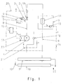
- a system shown schematically in Figure 1 has a in the Pump capacity changeable pump unit 1.
- the delivery head of the pump in Dependence on a predetermined setpoint is kept constant.
- this can also be used to change the delivery rate Principle of a guide vane or moving blade adjustment or combinations thereof be used.
- a head regulation can also be used, for which the delivery head of the pump as a function of Fluid flow is variable.
- a control valve 2 arranged in the system is provided with an actuator 3.
- the actuator 3 is equipped with control electronics 4 with an integrated positioner.
- the positioner is by a feedback throttle position 5 H sure that the actual throttle position H of the positioning device to the desired value H corresponds.
- a positioner is generally useful for higher demands on the control quality of the system. In addition, its use also depends on the design of the control valve and the operating conditions.
- a heated room 6 whose room temperature T R is to be controlled serves as an example for a consumer.
- the pump 1 conveys a fluid from a flow distributor 7 via a flow line 8 to the consumer 6 and from there via a return line 9 to one Return collector 10.
- Flow distributor 7 and return collector 10 are through each other a line 12 connected, and thus have the same pressure level.
- Flow distributor 7 and return collector 10 do not have the same pressure level, so must the pressure difference separately on further consideration in a known manner be taken into account, since it does not count towards the pipe network resistance of the system.
- On Place of heat supply via flow distributor 7 and return collector 10 can also a heat supply using a boiler, heat exchanger, etc. respectively.
- the room temperature T R room 6 is controlled by a system controller 13 with integrated measured value acquisition, which, in the event of a deviation from a desired setpoint set on the system controller 13, sends an actuating signal Y to an electronic unit 15 by means of the signal line 14.
- the electronics unit 15 causes a change in the fluid flow Q circulating through the system . This is done by changing the throttle position H of the control valve 2 and the delivery head P of the pump 1 in accordance with the setpoints H soll and P soll determined by the electronics unit 15 until 8 is discussed in more detail.
- H is intended by means of signal line 16 and P is to transmit by means of signal line 17th
- P is to transmit by means of signal line 17th
- a sensor 18 for detecting the delivery head P of the pump 1 and a sensor 19 for detecting the fluid flow Q are also integrated in the system.
- the sensor signal Q is fed into the electronics unit 15 by means of the signal line 20.
- the sensor signal P is guided by the signal line 21 to the pump control 22 and causes there by a change in the speed setting of the feed pitch P of the pump 1 to the target value P soll.
- Arrangements according to Fig. 1 are particularly useful if the pipe network resistance value is variable without an actuator. However, they can also be used with a constant resistance coefficient. In the case of the variable resistance coefficient, it is advantageous to permanently include the fluid flow Q in the determination of the setpoints for changing the throttle position H of the control valve and the delivery head P of the pump, in particular if the resistance coefficient fluctuates greatly. This will be discussed in more detail after the description of FIGS. 4 to 9.
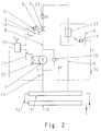
- Fig. 2 differs from Fig. 1 only in that the fluid flow Q is entered into the electronics unit 15 not by means of a signal line, but by hand. This makes sense for systems whose pipe network resistance coefficient is constant or nearly constant without a control valve. In these cases, the value of the fluid flow Q is only used to adjust the system. It is therefore possible to use a fluid flow meter 23 that is removed from the system again after adjustment.
- a device is e.g. B. the ultrasonic measuring device that can be applied to an already installed pipeline outside. This also makes it easy to repeat after changes in the pipe system. With an arrangement of a hydraulic system according to FIG. 2, the system costs can thus be significantly reduced.
- the electronics unit 15 is used only for the regulation of the system. It can then be removed from the system and used for adjusting other systems.
- the setpoints for the adjustment of the throttle position H of the control valve 2 or the delivery head P of the pump 1 as a function of the control signal Y, determined with the aid of the electronics unit 15, are stored in the control electronics 4 of the control valve 2 or the pump control 22 after the adjustment process.
- the control signal Y of the system controller 11 is fed into the control electronics 4 or the pump control 22, where the setpoints for the change in the throttle position or the delivery head are formed on the basis of the stored dependency.
- control electronics 4 of the control valve 2 and the pump control 22 already with appropriate electronic components for the deposit equipped with the dependency determined by the electronics unit 15. Otherwise it is it is possible with simple means to create a corresponding possibility.
- the arrangement according to FIG. 3 is both for systems according to FIG. 1 and for systems 2 can be used.
- FIG. 4 shows a schematic representation of the main functions of the electronic unit 15.
- the upper field shows schematically the determination of the flow characteristic D from the desired path characteristic S and the consumer characteristic V. This will be discussed in more detail in the description of FIG. 5.
- the lower field shows the determination of the control valve characteristic curve, which shows the dependence of the throttle position H on the control signal Y. This is discussed in more detail in FIG. 9.
- FIG. 5 shows the determination of the flow characteristic D from the consumer characteristic V and the desired optimal path characteristic S in a three-dimensional axonometric form with the axes Q, R and Y.
- Consumer characteristic curve V and distance characteristic curve S are either entered into the electronics unit 15 or selected or modified, if necessary, from a range of technically relevant characteristic curves V and S which are stored in the electronics unit 15. This can e.g. B. within the framework of the adjustment of the system. The input of V and S takes place e.g. B. manually by entering characteristic points or via a suitable PC interface. V is often based on physical systems of equations, e.g. B. for heat exchangers from the relevant literature, or from experience or measurements. 5, V and D already correspond to the range of R and Q required in a specific system.
- the dependence of the fluid flow Q circulating in the system on the actuating signal Y of the system controller 11 is used as the flow characteristic D here.
- the dependency of the fluid flow Q that is usually used on the throttle position H of the control valve could also be defined as a flow characteristic.
- the use of the dependence of the fluid flow Q on the actuating signal Y has the advantage that all axes of the representations in FIGS. 5 to 9 have the same, preferably linear division and are therefore advantageous to handle.
- the consumer characteristic curve V shows the dependence of the controlled variable R on the fluid flow Q and the path characteristic curve the dependency of the controlled variable R on the control signal Y.
- E can either be the actual controlled variable or a variable that directly influences it. In the case of room temperature control, for example, the heat output could act as such a variable.
- the sizes Q, R and Y are usually given as percentages related to the respective maximum or nominal value. However, they can also be applied with their physical units. This also applies to the quantities P, k v and H shown in FIGS. 6 to 9 .
- the flow characteristic D is determined from the coordinators of the characteristic S and the consumer characteristic V according to the normal axonometric method. This is shown in FIG. 5 on the basis of point A of the characteristic curve S. Point A has the coordinates R A and Y A. This results in the coordinates Y A and Q A for the associated point E of the flow characteristic D. By returning the point A via the consumer characteristic V to the axis Q , Q A is obtained . Soldering point A back to axis Y gives Y A. Q A and Y A form the coordinates of the point E of the flow characteristic D.
- the required flow characteristic curve can be determined once, e.g. B. at Consumers with constant consumer characteristics. It is also possible to get one perform dynamic adaptation of the flow characteristic for consumers, whose consumer characteristic changes due to operational reasons. The influencing factors the consumer characteristic is recorded by measurement technology and by the electronics unit 15 continuously evaluated to generate the current consumer characteristics.
- Fig. 6 shows the principle of the implementation of the flow characteristic D in the hydraulic system by the interaction of the pump and control valve in a three-dimensional axonometric representation with the axes, Q, P and Y.
- FIG. 6 It is advantageous to create FIG. 6 in a system-specific manner as part of the normal adjustment process, it generally being sufficient to adjust an operating point. It is expedient to use the full-load operating point Z with the maximum fluid flow Q 100 implemented in the system for the adjustment.
- the setpoints of the delivery head of the pump P and throttle position H of the control valve are adjusted by means of the electronics unit 15 until the fluid flow Q 100 has set in the system.
- the control signal Y 100 is assigned to the resulting values for the delivery head P z and for the throttle position H z . It must be ensured that Pz is not set higher than necessary and that the control valve has sufficient authority.
- the adjustment process can also be automated.
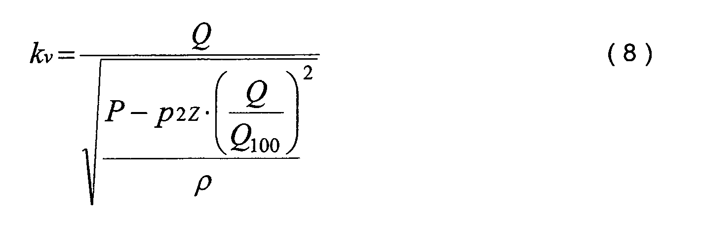
- the amount of k vz is determined from FIG. 9 with the aid of the throttle position Hz set during the adjustment. This will be discussed in more detail in the description of FIG. 9.
- a minimum delivery head of the pump P is selected as a function of the fluid flow Q from a pump and plant technology perspective. This dependence is referred to as the setpoint delivery head characteristic P.
- the course of P soll is primarily determined by the speed range and the efficiency of the pump. The course is generally limited on the one hand by the pipe network resistance or the minimum possible delivery head of the pump and on the other hand by the maximum possible delivery head of the pump.
- the minimum delivery head characteristic P min and the maximum P max is indicated in FIG. 6 by a dash-dotted line.
- an operating point curve B is determined using the method described in FIG. 7.
- an operating point of the system is defined in that a fluid flow Q corresponding to the flow characteristic D is circulated in the system to an actuating signal Y , the hydraulic resistance of the pipe network being equal to the delivery head of the pump.
- k VA is the k v value of the control valve belonging to the control signal Y A , which is necessary for realizing the point E of the flow characteristic curve D.
- the normal projection of the operating point l in the QY plane gives the point E of the flow characteristic D.
- the normal projection of l in the PQ plane results in the point M of the head characteristic P des . So derived therefrom is generally true that the normal projection of the operating points of curve B in the PQ plane with the flow-head characteristic P to coincide and the normal projection of the flow-head characteristic P should not follow the description in the area K, coincides with the operating points of curve B.
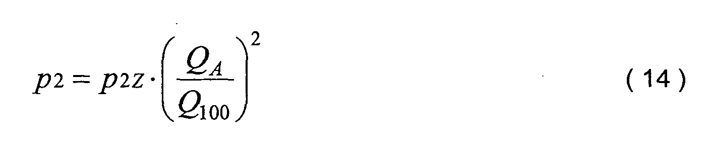
- the graphic representation shows the effect of non-compliance with the above condition. Is z. For example, if the delivery head set at point E on the pump is greater than P E , the intersection of the delivery head of the pump and the hydraulic resistance of the pipe network p 1 and p 2 in the actuating signal Y A is at a flow rate greater than Q A. The flow characteristic is no longer maintained. Conversely, if the head of the pump is lower and the point of intersection is lower than Q A , the flow characteristic is also not maintained.
- FIG. 7 shows the determination of the operating point curve B from the preselected delivery head characteristic curve P soll using this law.
- B is obtained as a sectional curve of the surface K with the surface L, whose normal projection in the plane of the delivery head PQ characteristic curve P will results.
- the operating point 1 belonging to point E of the flow characteristic D is the intersection of the curve of the hydraulic resistance p 1 and p 2 with the area K. For all other points of the flow characteristic D result the corresponding operating points according to the same principle. All curves of the hydraulic resistance together form a surface T whose intersection curve with the surface K is the operating point curve B.
- the throttle position H z belonging to Y 100 is determined as described in FIG. 6.
- H z will generally be less than the maximum possible value H 100 .
- the k v value k VZ belonging to Hz can be determined with the help of the basic characteristic G of the control valve.
- the basic characteristic curve G shows the dependence of the k v value on the throttle position H of the control valve. Since Hz is less than H 100 , k VZ is also less than the maximum k v value k VS of the control valve.
- p 2 is determined from the measured value of the delivery head of the pump P and the p 1 calculated with the k v value. This is much more precise than the purely arithmetical method and sufficient for standard requirements. A further improvement in accuracy is obtained by measuring the hydraulic resistance p 1 of the control valve during the adjustment process.
- a further improvement of the accuracy is through the adjustment not only of the full load operating point Z, but of several operating points in the Partial load range possible.
- Another possibility consists in permanently introducing the Q signal into the electronics unit 15 and comparing it there with the respective target value in accordance with the assignment of the actuating signal Y and fluid flow Q in accordance with the flow characteristic curve D. In the event of deviations, the setpoints of delivery head P and / or throttle position H are changed until the setpoint of the fluid flow Q is reached. This option is also available for systems with constant resistance coefficients ⁇ of the pipe network components without control valve.
- the resistance coefficient of pipe network components can e.g. B. by Changes to the pipe network, due to contamination or incrustations or also change by additional regulating and control devices on the consumer.
- the realization of an optimal flow characteristic and thus an optimal one Line characteristic leads to an improvement in the control quality.
- the authority of Control valve can be downsized. This reduces the hydraulic resistance the system and thus the required delivery rate and the energy requirements of the Pump.
- control valve requirements are low, so that practically only the pump parameters such as B. speed range, minimum Head, efficiency, etc. are determining.
- the Preselection of a fluid flow characteristic an additional optimization of the pressure level to the minimum required value.
- the energy consumption of the pump is in significantly minimized.
- the preselection of the control valve characteristic curve is appropriate for systems in which the actuator requirements, such as. B. noise generation, Cavitation, positional ratio, etc. are decisive.
- both the control valve characteristic and the delivery head characteristic also changed within the permissible limits, whereby is optimized for the lowest possible head curve. It is also there possible, in certain fluid flow areas of the system only the pump head to change and leave the throttle position of the control valve unchanged, or to change the throttle position of the control valve and the pump head to leave unchanged. This way a wide range can be found System technology requirements are met, so that practically for every system generates an optimal characteristic curve with minimal energy consumption of the pump can be.
- dependencies of the respective graphically represented in FIGS. 4 to 9 physical quantities are stored in the electronics unit or are from of the electronics unit in the manner described above. Individual or too all sizes or dependencies can vary depending on the structure of the electronic unit modified and adapted to plant parameters. The type of determination or
- Modification is carried out depending on the design of the electronics unit at the manufacturer specified or when starting up a system in the electronics unit entered or adjusted.
- the electronic unit determines with the help of the stored Dependencies from the command value initiated, the setpoints for the throttle position the control valve and the delivery head of the pump and directs the corresponding Signals to the control valve and pump, creating the desired control technology optimal and energy-saving operation of the system is achieved.
- the necessary hardware and software is provided for this purpose.
- an admixing line 24 and a fitting 25, here in the form of a backflow preventer, have been added. Fluid is returned from the return line 9 to the supply line 8 through the admixing line 24.
- the fitting 25 In the full load case of the system with maximum thermal output, the fitting 25 is in a closed position, as a result of which the bypass fluid flow has a value of zero.
- the control valve 2 With a decreasing load case and a reduction in the heat output, the control valve 2 begins to close and the valve 25 opens. In the rare case of zero load, the control valve 2 is closed and the entire fluid flow to be circulated flows through the admixing line 24.
- a control valve can also be provided.
- Q 1 corresponds to the fluid flow which is taken from a distribution system, here a flow distributor 7, and fed into the pipeline string shown.
- Q 2 corresponds to the fluid flow through the admixing line 24.
- Q is the total fluid flow from Q 1 and Q 2 flowing through the pump 1.
- the fluid flow Q has the flow temperature T v .
- FIG. 11 shows the determination of the flow characteristic D from the consumer characteristic V and the desired linear path characteristic S in an axonometric representation with the axes Q, Y and W, where W is the thermal output of the heat exchanger 11.
- the structure of FIG. 11 corresponds to that of FIG. 5.
- the room temperature is kept constant in that the heat output W of the heat exchanger 11 is constantly adapted to the heat loss in the room. Every change in the heat output or heat loss leads to a proportional change in the room temperature T R.
- the thermal output can also be used to linearize the characteristic curve S.
- the use of heat output offers the advantage of a simple pre-calculation of a system, since relatively precise calculation formulas are available for practically all embodiments of heat exchangers.
- the curve of the consumer characteristic curve V results from the known equations for calculating the thermal output of the heat exchanger and for mixing the two fluid flows Q 1 and Q 2 . Since such systems generally consist of standardized components in a standardized arrangement, a consumer characteristic curve suitable for a wide range of applications can be derived from this. The result is then the thermal output W assigned to the respective fluid flow Q in accordance with the consumer characteristic curve V , including the flow temperature Tv assigned to Q. It is also possible to determine the consumer characteristic curve in the course of the adjustment based on the system using the known physical equations.
- the flow characteristic curve is realized by the interaction of pump 1 and control valve 2, analogously to the procedure described above.
- the fluid flow is not reduced to zero, but to a minimum value Q min .
- This is chosen so that the performance characteristics of a heat exchanger or the exposure to a heat exchanger surface is still sufficiently uniform. This improves the control behavior in the low load range and prevents the heat exchanger from freezing.
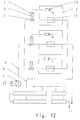
- Fig. 12 shows schematically simplified an advantageous example of a consumer group of a heating system in which a pump 1 supplies several rooms 6 with different, only partially different or even the same flow characteristics.
- the system has already been set up here too.
- the pipe resistance of the pipes 8, 9 must have a negligibly small share in the total pipe resistance. Because with a high resistance, for example at a great distance or a design with low pressure loss, fluid flow fluctuations due to different load states of the individual consumers 6 lead to a distortion of the flow characteristic and thus to a deterioration in the control quality.
- This distortion can be obtained by a correction of P to downward, starting from the full load operating point Z, the compensated in this conduit 8, 9 flowing fluid stream in response thereto. This is done in that, according to the dependency of the pipeline resistance on the fluid flow, the setpoint value P soll of the pump head is reduced when the fluid flow in the pipeline 8 and 9 decreases. The reduction of P soll thus corresponds to the decrease in pipe resistance due to the decreasing flow velocity.
- the advantage of this procedure lies in the fact that only the delivery head setpoint P should be corrected for the pump 1.
- the elaborate correction of the throttle positions of all control valves 2 can then be dispensed with.
- the resistance of the pipeline 8, 9 between the distributor / collector 7/10 and the consumer group is the same for all consumers, this procedure is possible.
- commercially available pumps offer the possibility of setting a corresponding head characteristic.
- the most cost-effective way to do this is with commercially available pumps with variable head characteristics that are generated from pump-internal data.
- the drop in the delivery head characteristic curve is mostly linear, so it does not exactly correspond to the quadratic dependence between pipeline resistance and fluid flow.
- the accuracy that can be achieved is justifiable if the proportion of pipeline losses in pipeline 8, 9 between distributor / collector 7/10 and consumer group is not too high.
- the fluid flow is measured and a delivery head characteristic with a quadratic dependency between the fluid flow and delivery head is formed.
- an actuating signal Y of a room temperature controller 13 does not have to be sent to the pump control 22, but only to the control electronics 4 of the control fittings 2.
- the pipe resistance of the pipe 8, 9 between manifold and The consumer group is determined during the adjustment of the system and by measurement, calculation or based on appropriate experience with comparable plants. Another option is not just that Full load operating point, but also one or more partial load operating points advocateregulieren.
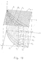
- the associated flow characteristic D can be determined for each consumer of FIG. 12 analogously to the principle described in FIG.
- the operating point curve B associated with each consumer 6 can then be determined according to the principle of FIG. 7 and the throttle position of the control valve 2 according to the principle of FIG.
- D 1 to D 3 are the flow characteristics of three consumers used only as examples.
- K 1 to K 3 represent the corresponding cylinder surfaces analogous to FIG. 7.
- B 1 to B 3 are the associated operating point curves of the consumers 6 to be operated.
- FIG. 14 shows a simplified schematic such facility.
- a pump control valve unit 26 are one of the other figures known pump unit 1 including pump control 22 and a control valve 2 with actuator 3 and control electronics 4 combined.
- the System is shown in the regulated state without electronics unit 15.
- the law of adjustment for the delivery head of the pump and the throttle position of the The control valve is in the pump control 22 or in the control electronics 4 Control valve 2 saved.
- Each pump control valve unit 26 only generates the delivery head that is required to supply the associated room 6.
- the flow line 8 and the return line 9 are advantageously as a ring line trained, since pressure fluctuations are minimized.
- the revolution of the Fluids in the ring line are carried out by a pump, not shown here, which is used in conventional pumps Systems supplied the distributor.
- the reduced pump head leads in connection with the larger number of pumps to smaller, more compact and easy-to-assemble pump control valve units 26. These can be made from inexpensive, space-saving pumps and control valves exist.
- a Integration of a control valve into a pump housing or a block unit Pump and control valve are possible.
- the setpoints for the delivery head are determined by means of the electronics unit 15 the pump 1 and the throttle position of the control valve 2 adjusted until the required fluid flow per room is set, the electronics unit 15 necessary authority of the control valve 2 is taken into account.
- the entire balancing process can run automatically.
- the resistance of the pipe network components Without a control valve the value of the delivery head available in the electronics becomes and the Kv value derived from the throttle position of the control valve Electronics unit calculated. This method is much more precise than the previous one usual forecasts. From the setting data of the full load operating point the electronics unit 15 automatically determines the adjustment law for the Setpoints of the delivery head and the throttle position of the control valve for the entire Range.
Landscapes
- Engineering & Computer Science (AREA)
- Physics & Mathematics (AREA)
- Fluid Mechanics (AREA)
- Mechanical Engineering (AREA)
- General Engineering & Computer Science (AREA)
- General Physics & Mathematics (AREA)
- Automation & Control Theory (AREA)
- Chemical & Material Sciences (AREA)
- Analytical Chemistry (AREA)
- Fluid-Pressure Circuits (AREA)
- Flow Control (AREA)
- Control Of Positive-Displacement Pumps (AREA)
Abstract
Description
- Fig. 1
- eine schematisch dargestellte Anlage, bei der ein Stellsignal und ein Fluidstromsignal in eine Elektronikeinheit eingeleitet werden.
- Fig. 2
- eine schematisch dargestellte Anlage, bei der nur ein Stellsignal in eine Elektronikeinheit eingeleitet wird.
- Fig. 3
- eine schematisch dargestellte Anlage, bei der die Elektronikeinheit nur zum Zwecke der Einregulierung der Anlage verwendet wird.
- Fig. 4
- eine schematische Darstellung der Hauptfunktionen der Elektronikeinheit.
- Fig. 5
- die Ermittlung der Durchflußkennlinie.
- Fig. 6
- das Prinzip der Realisierung der Durchflußkennlinie.
- Fig. 7
- die Ermittlung der Betriebspunktekurve aus vorgewähltem Sollwert der Förderhöhe der Pumpe und Durchflußkennlinie.
- Fig. 8
- Die Ermittlung der Betriebspunktekurve aus vorgewählter Stellarmaturenkennlinie und Durchflußkennlinie.
- Fig. 9
- die Ermittlung des Hubes bzw. der Stellarmaturenkennlinie.
- Fig. 10
- eine schematisch dargestellte Anlage mit einer Durchfluß-Beimisch-Regelung.
- Fig. 11
- die Ermittlung der Durchflußkennlinie der Anlage von Fig. 10.
- Fig. 12
- eine schematisch dargestellte Anlage, bei der eine Pumpe mehrere Verbraucher versorgt.
- Fig. 13
- die Ermittlung der Durchflußkennlinie der Anlage von Fig. 12.
- Fig. 14
- schematisch vereinfacht einen Ausschnitt einer Heizungsanlage mit PumpenStellarmaturen-Einheiten für jeden Raum.




- a
- = Autorität der Stellarmatur
- A
- = Ein Punkt der Streckenkennlinie S
- B
- = Betriebspunktekurve der hydraulischen Anlage
- C
- = der zur Regelgröße RA gehörige Punkt der Verbraucherkennlinie V
- D
- = Durchflußkennlinie der hydraulischen Anlage
- E
- = der aus dem Fluidstrom QA und dem Stellsignal YA sich ergebende Punkt der Durchflußkennlinie D
- G
- = Grundkennlinie der Stellarmatur
- H
- = Drosselstellung der Stellarmatur (bei einem Stellventil der Hub)
- Hsoll
- = Sollwert der Drosselstellung der Stellarmatur
- Hz
- = Drosselstellung der Stellarmatur beim Stellsignal Y 100, Fluidstrom Q 100 und Förderhöhe der Pumpe Pz
- H100
- = Drosselstellung der Stellarmatur im voll geöffneten Zustand
- l
- = der zu Punkt E der Durchflußkennlinie D gehörige Punkt der Betriebspunktekurve B
- K
- = Zylinderfläche senkrecht zur Q - Y -Ebene, deren Schnitt mit der Q - Y - Ebene die Durchflußkennlinie D ergibt
- kv
- = kv-Wert der Stellarmatur
- kVA
- = kv-Wert der Stellarmatur beim Stellsignal YA
- kVS
- = kv-Wert der Stellarmatur in voller Offenstellung (Serien kVS-Wert)
- kvz
- = kv-Wert der Stellarmatur bei der Drosselstellung Hz
- L
- = Zylinderfläche senkrecht zur P-Q-Ebene, deren Schnitt mit der P-Q- Ebene die Förderhöhenkennlinie Psoll ergibt.
- M
- = der zu Punkt l der Betriebspunktekurve B gehörige Punkt der Förderhöhenkennlinie Psoll
- N
- = der zum Stellsignal YA und zur Drosselstellung HA gehörige Punkt der Verstellgesetzmäßigkeit der Drosselstellung der Stellarmatur Hsoll = ƒ(Y)
- O
- = der zum Stellsignal YA und zum kv-Wert kVA gehörige Punkt der Kennlinie kv = ƒ(Y)
- P
- = Förderhöhe der Pumpe
- PE
- = Förderhöhe der Pumpe beim Fluidstrom QA
- Pmax
- = maximale Förderhöhe der Pumpe in Abhängigkeit vom Förderstrom Q
- Pmin
- = minimale Förderhöhe der Pumpe in Abhängigkeit vom Förderstrom Q
- Psoll
- = Sollwert der Förderhöhe der Pumpe in Abhängigkeit von Fluidstrom Q.
- PZ
- = Förderhöhe der Pumpe beim Fluidstrom Q 100 und beim Stellsignal Yioo
- p1+ p2=
- Widerstand des Rohrnetzes
- p1
- = Widerstand der Stellarmatur
- p2
- = Widerstand der Rohrleitungskomponenten ohne Stellarmatur
- p1E
- = Widerstand der Stellarmatur bei der zum Stellsignal YA gehörigen Drosselstellung HA der Stellarmatur und dem Fluidstrom QA
- p2E
- = Widerstand der Rohrleitungskomponenten ohne Stellarmatur beim Fluidstrom QA
- p1Z
- = Widerstand der Stellarmatur bei der Drosselstellung Hz der Stellarmatur und beim Fluidstrom Qioo
- p2Z
- = Widerstand der Rohrleitungskomponenten ohne Stellarmatur beim Fluidstrom Q 100
- Q
- = Fluidstrom der hydraulischen Anlage
- QA
- = der zur Regelgröße RA gehörige Punkt des Fluidstromes Q
- Qmin
- = Minimalwert des Fluidstromes Q
- Q100
- = maximaler Fluidstrom der hydraulischen Anlage
- R
- = Regelgröße der hydraulischen Anlage
- RA
- = Regelgröße im Punkt A der Streckenkennlinie S
- R100
- = Regelgröße beim Fluidstrom Q 100
- S
- = Streckenkennlinie der hydraulischen Anlage
- T =
- Fläche des Widerstandes p1 + p2
- Tv =
- Vorlauftemperatur
- TR =
- Raumtemperatur
- V =
- Verbraucherkennlinie
- W =
- Wärmeleistung
- w =
- Strömungsgeschwindigkeit in der Rohrleitungskomponente
- Y =
- Stellsignal des Anlagenreglers
- YA =
- Stellsignal bei der Regelgröße RA
- Y100 =
- Stellsignal bei der Regelgröße R 100
- Z =
- Volllast-Betriebspunkt beim Fluidstrom Q 100, Stellsignal Y 100 und Förderhöhe der Pumpe Pz
- ρ =
- Dichte des Fluids
- ζ =
- Widerstandsbeiwert einer Rohrleitungskomponente (=zeta-Wert)
- 1
- Pumpenaggregat
- 2
- Stellarmatur
- 3
- Stellantrieb
- 4
- Regelelektronik
- 5
- Rückführung
- 6
- Raum, Verbraucher
- 7
- Vorlaufverteiler
- 8
- Vorlaufleitung
- 9
- Rücklaufleitung
- 10
- Rücklaufsammler
- 11
- Wärmetauscher
- 12
- Leitung
- 13
- Anlagenregler
- 14
- Signalleitung
- 15
- Elektronikeinheit
- 16
- Signalleitung
- 17
- Signalleitung
- 18
- Sensor
- 19
- Sensor
- 20
- Signalleitung
- 21
- Signalleitung
- 22
- Pumpenregelung
- 23
- Fluidstrommeßgerät
- 24
- Beimischleitung
- 25
- Armatur
- 26
- Pumpen-Stellarmaturen-Einheit
Claims (29)
- System zur Beeinflussung eines Fluidstromes in einer hydraulischen Anlage, wobei mindestens eine in der Anlage angeordnete, in Förderhöhe und/oder Fördermenge veränderbare Pumpe ein Fluid unter Überwindung des Rohrnetzwiderstandes umwälzt und in der hydraulischen Anlage eine Stellarmatur zur Beeinflussung der Transportleistung des Fluids angeordnet ist, dadurch gekennzeichnet, daß in der hydraulischen Anlage eine Durchflußkennlinie D, gebildet aus Wertepaaren von Fluidstrom Q und Stellsignal Y eines Anlagenreglers (13), oder gebildet aus Wertepaaren von Fluidstrom Q und Drosselstellung H der Stellarmatur (2), erzeugt wird, indem für jedes Wertepaar die Förderhöhe P der Pumpe (1) und der Rohrnetzwiderstand p 1 + p 2 auf einen gleichen Wert eingestellt oder eingeregelt werden.
- System nach Anspruch 1, dadurch gekennzeichnet, daß durch eine Elektronikeinheit (15) ein Regler von mindestens einer in der Anlage angeordneten Pumpe (1) und ein Stellantrieb (2) von einer in der Anlage angeordneten Stellarmatur (3) zu einer regelungstechnischen und/oder steuerungstechnischen Stelleinheit verbunden sind.
- System nach Anspruch 1 und 2, dadurch gekennzeichnet, daß der Rohrnetzwiderstand durch Veränderung der Drosselstellung einer Stellarmatur (3) eingestellt bzw. eingeregelt wird.
- System nach einem der Ansprüche 1 - 3, dadurch gekennzeichnet, daß die Veränderung der Förderhöhe und/oder Fördermenge der Pumpe (1) durch Drehzahlveränderung und/oder durch eine Leitschaufelverstellung erfolgt.
- System nach einem der Ansprüche 1 - 4, dadurch gekennzeichnet, daß bei einer Drehzahlveränderung, Leitschaufel- und/oder Laufschaufelverstellung die Förderhöhe der Pumpe (1) die Regelgröße ist.
- System nach einem der Ansprüche 1 - 5, dadurch gekennzeichnet, daß die Förderhöhenregelung der Pumpe (1) nach dem Prinzip einer konstanten Förderhöhe bei vorgegebenen Sollwert arbeitet.
- System nach einem der Ansprüche 1 - 6, dadurch gekennzeichnet, daß die Elektronikeinheit (15) aus der erwünschten Streckenkennlinie und der Verbraucherkennlinie eine zugehörige optimale Durchflußkennlinie aus den Koordinaten der Strecken- bzw. Verbraucherkennlinie nach dem im Prinzip bekannten normalaxonometrischen Verfahren ermittelt.
- System nach einem der Ansprüche 1 - 7, dadurch gekennzeichnet, daß die optimale Durchflußkennlinie als Funktion des Fluidstromes in Abhängigkeit vom Stellsignal des Anlagenreglers- oder Steuergerätes gebildet ist.
- System nach einem der Ansprüche 1 - 8, dadurch gekennzeichnet, daß die optimale Durchflußkennlinie extern gebildet und in die Elektronikeinheit eingegeben wird.
- System nach einem der Ansprüche 1 - 9, dadurch gekennzeichnet, daß das Stellsignal des Anlagenreglers- oder Steuergerätes, das Signal der Förderhöhe der Pumpe (1) und das Fluidstromsignal in die Elektronikeinheit (15) permanent eingeleitet werden und die Elektronikeinheit (15) die Sollwerte für die Förderhöhe der Pumpe und die Drosselstellung der Stellarmatur (13) permanent ausgibt.
- System nach den Ansprüchen 1 - 10, dadurch gekennzeichnet, daß das Stellsignal des Anlagenreglers (13) oder- steuergerätes permanent und das Signal für die Förderhöhe der Pumpe (1) und das Fluidstromsignal im Rahmen der Einregulierung der Anlage in die Elektronikeinheit (15) eingeleitet werden und die Elektronikeinheit (15) die Sollwerte für die Förderhöhe der Pumpe und die Drosselstellung der Stellarmatur (3) permanent ausgibt.
- System nach den Ansprüche 1 - 11, dadurch gekennzeichnet, daß das Signal für die Förderhöhe der Pumpe (1) und das Fluidstromsignal im Rahmen der Einregulierung der Anlage in die Elektronikeinheit (15) eingegeben werden, die Elektronikeinheit (15) die Sollwerte für die Förderhöhe der Pumpe (1) und die Drosselstellung der Stellarmatur (3) in Abhängigkeit vom Stellsignal ermittelt und diese Werte im Regler der Pumpe bzw. im Stellantrieb der Stellarmatur gespeichert und beim Betrieb der Anlage permanent ausgegeben werden, wobei das Stellsignal des Anlagenreglers oder Steuergerätes sowohl in den Regler der Pumpe, als auch in den Stellantrieb permanent eingeleitet wird.
- System nach einem der Ansprüche 1 - 12, dadurch gekennzeichnet, daß die Elektronikeinheit (15) ein permanenter oder temporärer Bestandteil der hydraulischen Anlage darstellt.
- System nach einem der Ansprüche 1 - 13, dadurch gekennzeichnet, daß die Elektronikeinheit (15) ganz oder teilweise in die Regelelektronik drehzahlgeregelter Pumpen (1) und/oder den Stellantrieb und/oder den Stellungsregler der Stellarmatur (3) integriert ist und daß die Teile der Elektronikeinheit (15) durch Daten oder Signale übertragende Verbindungen miteinander verbunden sind.
- System nach einem der Ansprüche 1 - 14, dadurch gekennzeichnet, daß die Elektronikeinheit (15) als eigenständige Baueinheit ausgebildet ist.
- System nach einem der Ansprüche 1 -15, dadurch gekennzeichnet, daß der Stellantrieb (3) der Stellarmatur (2) einen Stellungsregler aufweist.
- System nach einem der Ansprüche 1 - 16, dadurch gekennzeichnet, daß Pumpe (1) und Stellarmatur (2) als eine Baueinheit ausgebildet wird.
- System nach einem der Ansprüche 1 - 17, dadurch gekennzeichnet, daß Pumpe (1) und Stellarmatur (2) in einem gemeinsamen Gehäuse angeordnet sind.
- System nach den Ansprüchen 1 - 18, dadurch gekennzeichnet, daß bei einem Stillstand der Pumpe (1) die Stellarmatur (2) geschlossen wird.
- System nach einem der Ansprüche 1 - 19, dadurch gekennzeichnet, daß in die Elektronikeinheit (15) eine aus pumpen - und anlagentechnischer Sicht minimal mögliche Förderhöhe der Pumpe (1) in Abhängigkeit vom Fluidstrom vorgewählt wird und daß die Elektronikeinheit (15) die zugehörige Stellarmaturenkennlinie unter Einbeziehung der minimal und maximal zulässigen Kennlinienverläufe der Stellarmatur ermittelt.
- System nach einem der Ansprüche 1 - 20, dadurch gekennzeichnet, daß eine aus stellarmaturen- und anlagentechnischer Sicht günstige Stellarmaturenkennlinie vorgewählt wird und daß die Elektronikeinheit (15) die zugehörige Förderhöhe der Pumpe (1) in Abhängigkeit vom Fluidstrom unter Einbeziehung der pumpentechnischen Möglichkeiten ermittelt.
- System nach einem der Ansprüche 1 - 21, dadurch gekennzeichnet, daß in der Elektronikeinheit (15) eine Palette anlagentechnisch relevanter Strecken- und Verbraucherkennlinien abgelegt sind und anlagenspezifisch ausgewählt bzw. modifiziert werden.
- System nach einem der Ansprüche 1- 22, dadurch gekennzeichnet, daß in der Elektronikeinheit (15) eine Palette pumpentechnisch relevanter Förderhöhenkennlinien abgelegt sind und pumpenspezifisch ausgewählt bzw. modifiziert werden.
- System nach einem der Ansprüche 1 - 23, dadurch gekennzeichnet, daß in der Elektronikeinheit (15) eine Palette armaturentechnisch relevanter Stellarmaturenkennlinien abgelegt sind und armaturenspezifisch ausgewählt bzw. modifiziert werden.
- System nach einem der Ansprüche 1-24, dadurch gekennzeichnet, daß in der Elektronikeinheit (15) eine Palette technisch relevanter Durchflußkennlinien abgelegt sind und anlagenspezifisch ausgewählt bzw. modifiziert werden.
- System nach einem der Ansprüche 1 - 25, dadurch gekennzeichnet, daß in der hydraulischen Anlage eine Beimischleitung (24) zwischen einer Vorlaufleitung (8) und einer Rücklaufleitung (9) angeordnet ist, daß in der Beimischleitung (24) eine Armatur (25) mit veränderbarem Widerstand angeordnet ist und daß eine kombinierte Durchfluß-Beimisch-Regelung Anwendung findet.
- System nach Anspruch 26, dadurch gekennzeichnet, daß es mit einer linearisierten Streckenkennlinie S und daraus abgeleiteten Durchflußkennlinie D versehen ist.
- System nach Anspruch 26 oder 27, dadurch gekennzeichnet, daß die Armatur (25) ein Rückflußverhinderer oder eine Stellarmatur ist.
- Verfahren zur Erzeugung optimaler Streckenkennlinien in hydraulischen Anlagen, dadurch gekennzeichnet, daß innerhalb einer Elektronikeinheit (15) aus der erwünschten optimalen Streckenkennlinie und der Verbraucherkennlinie die für die Anlage optimale Durchflußkennlinie ermittelt wird, daß die ermittelte optimale oder eine extern vorgegebene Durchflußkennlinie in der Anlage dadurch realisiert wird, daß die Elektronikeinheit (15) aus einer vorgewählten Förderhöhenkennlinie der Pumpe (1) die erforderlichen kv -Werte der Stellarmatur (2) oder aus einer vorgewählten Stellarmaturenkennlinie die erforderliche Förderhöhenkennlinie der Pumpe (1) nach dem Prinzip ermittelt, daß für jedes Wertepaar von Stellsignal des Anlagenreglers und Fluidstrom der Durchflußkennlinie die Förderhöhe der Pumpe (1) und der Rohrnetzwiderstand gleich sein müssen, daß aus den kv -Werten die Drosselstellungen der Stellarmatur (2) mit Hilfe der Grundkennlinie abgeleitet werden und daß die Elektronikeinheit (15) die einander zugeordneten Werte für die Förderhöhe der Pumpe (1) und die Drosselstellung der Stellarmatur (2) als Sollwerte in Abhängigkeit vom Stellsignal des Anlagenreglers an die Pumpenregelung bzw. den Stellantrieb der Stellarmatur (2) leitet.
Applications Claiming Priority (4)
| Application Number | Priority Date | Filing Date | Title |
|---|---|---|---|
| DE10163396 | 2001-12-21 | ||
| DE10163396 | 2001-12-21 | ||
| DE10257657A DE10257657A1 (de) | 2001-12-21 | 2002-12-07 | Hydraulische Anlage |
| DE10257657 | 2002-12-07 |
Publications (3)
| Publication Number | Publication Date |
|---|---|
| EP1321842A2 true EP1321842A2 (de) | 2003-06-25 |
| EP1321842A3 EP1321842A3 (de) | 2004-03-31 |
| EP1321842B1 EP1321842B1 (de) | 2006-02-22 |
Family
ID=26010844
Family Applications (1)
| Application Number | Title | Priority Date | Filing Date |
|---|---|---|---|
| EP02028445A Expired - Lifetime EP1321842B1 (de) | 2001-12-21 | 2002-12-19 | Hydraulische Anlage |
Country Status (3)
| Country | Link |
|---|---|
| EP (1) | EP1321842B1 (de) |
| AT (1) | ATE318423T1 (de) |
| DE (1) | DE50205869D1 (de) |
Cited By (1)
| Publication number | Priority date | Publication date | Assignee | Title |
|---|---|---|---|---|
| CN101825207B (zh) * | 2009-03-07 | 2011-10-26 | 张宇 | 节能型流量自动调节器及其在热网流量调节中的应用方法 |
Families Citing this family (1)
| Publication number | Priority date | Publication date | Assignee | Title |
|---|---|---|---|---|
| DE102009050083B4 (de) | 2009-10-20 | 2016-08-18 | Viessmann Werke Gmbh & Co Kg | Verfahren zur Bestimmung eines Volumenstroms in einer mit einer Strömungsmaschine und mit einer Regelungseinheit versehenen, geschlossenen Strömungsanlage |
Family Cites Families (4)
| Publication number | Priority date | Publication date | Assignee | Title |
|---|---|---|---|---|
| US3202208A (en) * | 1962-08-22 | 1965-08-24 | American Hydrotherm Corp | Heat exchange system with automatic pump control |
| DE4019503A1 (de) * | 1990-06-19 | 1992-01-02 | Heimeier Gmbh Metall Theodor | Einrichtung zur steuerung des stellventiles einer zentralheizungsanlage |
| DE4203613C2 (de) * | 1992-02-07 | 1998-01-22 | Sandler Energietechnik | Steuersystem für Raumheizanlagen |
| DE19912588A1 (de) * | 1999-03-20 | 2000-09-21 | Ksb Ag | Fluidtransportsystem |
-
2002
- 2002-12-19 EP EP02028445A patent/EP1321842B1/de not_active Expired - Lifetime
- 2002-12-19 AT AT02028445T patent/ATE318423T1/de not_active IP Right Cessation
- 2002-12-19 DE DE50205869T patent/DE50205869D1/de not_active Expired - Lifetime
Cited By (1)
| Publication number | Priority date | Publication date | Assignee | Title |
|---|---|---|---|---|
| CN101825207B (zh) * | 2009-03-07 | 2011-10-26 | 张宇 | 节能型流量自动调节器及其在热网流量调节中的应用方法 |
Also Published As
| Publication number | Publication date |
|---|---|
| ATE318423T1 (de) | 2006-03-15 |
| DE50205869D1 (de) | 2006-04-27 |
| EP1321842A3 (de) | 2004-03-31 |
| EP1321842B1 (de) | 2006-02-22 |
Similar Documents
| Publication | Publication Date | Title |
|---|---|---|
| EP1163478B1 (de) | Fluidtransportsystem | |
| EP2960587B1 (de) | Verfahren zum Begrenzen des Versorgungsstromes in einem Wärmeübertragungssystem | |
| EP2678563B1 (de) | Leistungsoptimiertes betreiben einer elektromotorisch angetriebenen pumpe durch mitkopplung | |
| WO2005024245A1 (de) | Steueranordnung und verfahren zur druckmittelversorgung von zumindest zwei hydraulischen verbrauchern | |
| EP0282886B1 (de) | Verfahren zum Steuern der Vorlauftemperatur einer Anlage zur Übertragung von Wärmeenergie | |
| DE102008057730A1 (de) | Verfahren zum Betreiben eines Systems zum Transport thermischer Energie über ein flüssiges Medium | |
| EP2874039A1 (de) | Steuerverfahren für ein Wärmeübertragungssystem sowie ein solches Wärmeübertragungssystem | |
| EP0881435A1 (de) | Zweistufen-Servoregler | |
| DE69804432T2 (de) | Vorrichtung zur Steuerung eines Durchflusses | |
| EP2985536A1 (de) | Regelverfahren für ein Pumpenaggregat | |
| EP3722680A1 (de) | Verfahren zur durchführung eines hydraulischen abgleichs eines heizsystems für ein gebäude sowie dazu ausgebildetes heizsystem | |
| EP3874338B1 (de) | Verfahren zum betreiben eines ventils, zugehörige elektronische ansteuereinheit und ventilantrieb | |
| EP1191287B1 (de) | Leitungssystem zur thermischen Energieübertragung | |
| EP3757396A1 (de) | Verfahren und system zur regelung eines medienparameters des mediums auf der sekundärseite eines wärmeübertragers | |
| EP2933502B1 (de) | Digitalhydraulisches Antriebssystem | |
| DE10144595B4 (de) | Zentralheizungsanlage | |
| EP1321842B1 (de) | Hydraulische Anlage | |
| DE10257657A1 (de) | Hydraulische Anlage | |
| AT411190B (de) | Heizanlage und/oder kühlanlage mit mindestens einer wärmequelle | |
| EP3757465A1 (de) | System und verfahren zur regelung eines medienparameters des mediums auf der sekundärseite eines wärmeübertragers | |
| AT6001U1 (de) | Heizanlage oder kühlanlage mit mindestens einer wärmequelle | |
| EP2442052A1 (de) | Verfahren zur regelung, welches in einer Heizungsanlage ausgeführt wird | |
| EP3350515B1 (de) | Verfahren und vorrichtung zum regeln einer temperatur eines fluiden trägermediums | |
| DE69400929T2 (de) | Flüssigkeits-Verteilnetz mit Regler | |
| DE102022103778A1 (de) | Verfahren zum Steuern einer Raumtemperatur, Heizungssystem zum Steuern einer Raumtemperatur und Steuervorrichtung zum Einsatz in einem Heizungssystem |
Legal Events
| Date | Code | Title | Description |
|---|---|---|---|
| PUAI | Public reference made under article 153(3) epc to a published international application that has entered the european phase |
Free format text: ORIGINAL CODE: 0009012 |
|
| AK | Designated contracting states |
Designated state(s): AT BE BG CH CY CZ DE DK EE ES FI FR GB GR IE IT LI LU MC NL PT SE SI SK TR |
|
| AX | Request for extension of the european patent |
Extension state: AL LT LV MK RO |
|
| PUAL | Search report despatched |
Free format text: ORIGINAL CODE: 0009013 |
|
| AK | Designated contracting states |
Kind code of ref document: A3 Designated state(s): AT BE BG CH CY CZ DE DK EE ES FI FR GB GR IE IT LI LU MC NL PT SE SI SK TR |
|
| AX | Request for extension of the european patent |
Extension state: AL LT LV MK RO |
|
| RIC1 | Information provided on ipc code assigned before grant |
Ipc: 7F 24D 19/10 B Ipc: 7G 05D 7/06 B Ipc: 7G 05D 16/20 A |
|
| 17P | Request for examination filed |
Effective date: 20040420 |
|
| 17Q | First examination report despatched |
Effective date: 20040806 |
|
| AKX | Designation fees paid |
Designated state(s): AT BE BG CH CY CZ DE DK EE ES FI FR GB GR IE IT LI LU MC NL PT SE SI SK TR |
|
| GRAP | Despatch of communication of intention to grant a patent |
Free format text: ORIGINAL CODE: EPIDOSNIGR1 |
|
| GRAS | Grant fee paid |
Free format text: ORIGINAL CODE: EPIDOSNIGR3 |
|
| GRAA | (expected) grant |
Free format text: ORIGINAL CODE: 0009210 |
|
| AK | Designated contracting states |
Kind code of ref document: B1 Designated state(s): AT BE BG CH CY CZ DE DK EE ES FI FR GB GR IE IT LI LU MC NL PT SE SI SK TR |
|
| PG25 | Lapsed in a contracting state [announced via postgrant information from national office to epo] |
Ref country code: SI Free format text: LAPSE BECAUSE OF FAILURE TO SUBMIT A TRANSLATION OF THE DESCRIPTION OR TO PAY THE FEE WITHIN THE PRESCRIBED TIME-LIMIT Effective date: 20060222 Ref country code: FI Free format text: LAPSE BECAUSE OF FAILURE TO SUBMIT A TRANSLATION OF THE DESCRIPTION OR TO PAY THE FEE WITHIN THE PRESCRIBED TIME-LIMIT Effective date: 20060222 Ref country code: SK Free format text: LAPSE BECAUSE OF FAILURE TO SUBMIT A TRANSLATION OF THE DESCRIPTION OR TO PAY THE FEE WITHIN THE PRESCRIBED TIME-LIMIT Effective date: 20060222 Ref country code: NL Free format text: LAPSE BECAUSE OF FAILURE TO SUBMIT A TRANSLATION OF THE DESCRIPTION OR TO PAY THE FEE WITHIN THE PRESCRIBED TIME-LIMIT Effective date: 20060222 Ref country code: IE Free format text: LAPSE BECAUSE OF FAILURE TO SUBMIT A TRANSLATION OF THE DESCRIPTION OR TO PAY THE FEE WITHIN THE PRESCRIBED TIME-LIMIT Effective date: 20060222 Ref country code: IT Free format text: LAPSE BECAUSE OF FAILURE TO SUBMIT A TRANSLATION OF THE DESCRIPTION OR TO PAY THE FEE WITHIN THE PRESCRIBED TIME-LIMIT;WARNING: LAPSES OF ITALIAN PATENTS WITH EFFECTIVE DATE BEFORE 2007 MAY HAVE OCCURRED AT ANY TIME BEFORE 2007. THE CORRECT EFFECTIVE DATE MAY BE DIFFERENT FROM THE ONE RECORDED. Effective date: 20060222 Ref country code: GB Free format text: LAPSE BECAUSE OF FAILURE TO SUBMIT A TRANSLATION OF THE DESCRIPTION OR TO PAY THE FEE WITHIN THE PRESCRIBED TIME-LIMIT Effective date: 20060222 |
|
| REG | Reference to a national code |
Ref country code: GB Ref legal event code: FG4D Free format text: NOT ENGLISH |
|
| REG | Reference to a national code |
Ref country code: CH Ref legal event code: EP |
|
| REG | Reference to a national code |
Ref country code: IE Ref legal event code: FG4D Free format text: LANGUAGE OF EP DOCUMENT: GERMAN |
|
| REF | Corresponds to: |
Ref document number: 50205869 Country of ref document: DE Date of ref document: 20060427 Kind code of ref document: P |
|
| PG25 | Lapsed in a contracting state [announced via postgrant information from national office to epo] |
Ref country code: BG Free format text: LAPSE BECAUSE OF FAILURE TO SUBMIT A TRANSLATION OF THE DESCRIPTION OR TO PAY THE FEE WITHIN THE PRESCRIBED TIME-LIMIT Effective date: 20060522 Ref country code: DK Free format text: LAPSE BECAUSE OF FAILURE TO SUBMIT A TRANSLATION OF THE DESCRIPTION OR TO PAY THE FEE WITHIN THE PRESCRIBED TIME-LIMIT Effective date: 20060522 Ref country code: SE Free format text: LAPSE BECAUSE OF FAILURE TO SUBMIT A TRANSLATION OF THE DESCRIPTION OR TO PAY THE FEE WITHIN THE PRESCRIBED TIME-LIMIT Effective date: 20060522 |
|
| PG25 | Lapsed in a contracting state [announced via postgrant information from national office to epo] |
Ref country code: ES Free format text: LAPSE BECAUSE OF FAILURE TO SUBMIT A TRANSLATION OF THE DESCRIPTION OR TO PAY THE FEE WITHIN THE PRESCRIBED TIME-LIMIT Effective date: 20060602 |
|
| PG25 | Lapsed in a contracting state [announced via postgrant information from national office to epo] |
Ref country code: PT Free format text: LAPSE BECAUSE OF FAILURE TO SUBMIT A TRANSLATION OF THE DESCRIPTION OR TO PAY THE FEE WITHIN THE PRESCRIBED TIME-LIMIT Effective date: 20060724 |
|
| NLV1 | Nl: lapsed or annulled due to failure to fulfill the requirements of art. 29p and 29m of the patents act | ||
| GBV | Gb: ep patent (uk) treated as always having been void in accordance with gb section 77(7)/1977 [no translation filed] |
Effective date: 20060222 |
|
| REG | Reference to a national code |
Ref country code: IE Ref legal event code: FD4D |
|
| PLBE | No opposition filed within time limit |
Free format text: ORIGINAL CODE: 0009261 |
|
| STAA | Information on the status of an ep patent application or granted ep patent |
Free format text: STATUS: NO OPPOSITION FILED WITHIN TIME LIMIT |
|
| PG25 | Lapsed in a contracting state [announced via postgrant information from national office to epo] |
Ref country code: BE Free format text: LAPSE BECAUSE OF NON-PAYMENT OF DUE FEES Effective date: 20061231 Ref country code: MC Free format text: LAPSE BECAUSE OF NON-PAYMENT OF DUE FEES Effective date: 20061231 Ref country code: CH Free format text: LAPSE BECAUSE OF NON-PAYMENT OF DUE FEES Effective date: 20061231 Ref country code: LI Free format text: LAPSE BECAUSE OF NON-PAYMENT OF DUE FEES Effective date: 20061231 |
|
| 26N | No opposition filed |
Effective date: 20061123 |
|
| EN | Fr: translation not filed | ||
| REG | Reference to a national code |
Ref country code: CH Ref legal event code: PL |
|
| BERE | Be: lapsed |
Owner name: KSB A.G. Effective date: 20061231 |
|
| PG25 | Lapsed in a contracting state [announced via postgrant information from national office to epo] |
Ref country code: AT Free format text: LAPSE BECAUSE OF NON-PAYMENT OF DUE FEES Effective date: 20061219 |
|
| PG25 | Lapsed in a contracting state [announced via postgrant information from national office to epo] |
Ref country code: FR Free format text: LAPSE BECAUSE OF FAILURE TO SUBMIT A TRANSLATION OF THE DESCRIPTION OR TO PAY THE FEE WITHIN THE PRESCRIBED TIME-LIMIT Effective date: 20070309 Ref country code: GR Free format text: LAPSE BECAUSE OF FAILURE TO SUBMIT A TRANSLATION OF THE DESCRIPTION OR TO PAY THE FEE WITHIN THE PRESCRIBED TIME-LIMIT Effective date: 20060523 Ref country code: CZ Free format text: LAPSE BECAUSE OF FAILURE TO SUBMIT A TRANSLATION OF THE DESCRIPTION OR TO PAY THE FEE WITHIN THE PRESCRIBED TIME-LIMIT Effective date: 20060222 |
|
| PG25 | Lapsed in a contracting state [announced via postgrant information from national office to epo] |
Ref country code: EE Free format text: LAPSE BECAUSE OF FAILURE TO SUBMIT A TRANSLATION OF THE DESCRIPTION OR TO PAY THE FEE WITHIN THE PRESCRIBED TIME-LIMIT Effective date: 20060222 |
|
| PG25 | Lapsed in a contracting state [announced via postgrant information from national office to epo] |
Ref country code: TR Free format text: LAPSE BECAUSE OF FAILURE TO SUBMIT A TRANSLATION OF THE DESCRIPTION OR TO PAY THE FEE WITHIN THE PRESCRIBED TIME-LIMIT Effective date: 20060222 Ref country code: LU Free format text: LAPSE BECAUSE OF NON-PAYMENT OF DUE FEES Effective date: 20061219 |
|
| PG25 | Lapsed in a contracting state [announced via postgrant information from national office to epo] |
Ref country code: CY Free format text: LAPSE BECAUSE OF FAILURE TO SUBMIT A TRANSLATION OF THE DESCRIPTION OR TO PAY THE FEE WITHIN THE PRESCRIBED TIME-LIMIT Effective date: 20060222 Ref country code: FR Free format text: LAPSE BECAUSE OF FAILURE TO SUBMIT A TRANSLATION OF THE DESCRIPTION OR TO PAY THE FEE WITHIN THE PRESCRIBED TIME-LIMIT Effective date: 20060222 |
|
| REG | Reference to a national code |
Ref country code: DE Ref legal event code: R081 Ref document number: 50205869 Country of ref document: DE Owner name: KSB SE & CO. KGAA, DE Free format text: FORMER OWNER: KSB AG, 67227 FRANKENTHAL, DE |
|
| PGFP | Annual fee paid to national office [announced via postgrant information from national office to epo] |
Ref country code: DE Payment date: 20220106 Year of fee payment: 20 |
|
| REG | Reference to a national code |
Ref country code: DE Ref legal event code: R071 Ref document number: 50205869 Country of ref document: DE |