EP1320284A2 - Circuit de commande à haut rendement pour Leds de couleur - Google Patents
Circuit de commande à haut rendement pour Leds de couleur Download PDFInfo
- Publication number
- EP1320284A2 EP1320284A2 EP02027332A EP02027332A EP1320284A2 EP 1320284 A2 EP1320284 A2 EP 1320284A2 EP 02027332 A EP02027332 A EP 02027332A EP 02027332 A EP02027332 A EP 02027332A EP 1320284 A2 EP1320284 A2 EP 1320284A2
- Authority
- EP
- European Patent Office
- Prior art keywords
- light emitting
- emitting diode
- coupled
- led
- inductor
- Prior art date
- Legal status (The legal status is an assumption and is not a legal conclusion. Google has not performed a legal analysis and makes no representation as to the accuracy of the status listed.)
- Granted
Links
Images


Classifications
-
- H—ELECTRICITY
- H05—ELECTRIC TECHNIQUES NOT OTHERWISE PROVIDED FOR
- H05B—ELECTRIC HEATING; ELECTRIC LIGHT SOURCES NOT OTHERWISE PROVIDED FOR; CIRCUIT ARRANGEMENTS FOR ELECTRIC LIGHT SOURCES, IN GENERAL
- H05B45/00—Circuit arrangements for operating light-emitting diodes [LED]
- H05B45/20—Controlling the colour of the light
- H05B45/24—Controlling the colour of the light using electrical feedback from LEDs or from LED modules
-
- H—ELECTRICITY
- H05—ELECTRIC TECHNIQUES NOT OTHERWISE PROVIDED FOR
- H05B—ELECTRIC HEATING; ELECTRIC LIGHT SOURCES NOT OTHERWISE PROVIDED FOR; CIRCUIT ARRANGEMENTS FOR ELECTRIC LIGHT SOURCES, IN GENERAL
- H05B45/00—Circuit arrangements for operating light-emitting diodes [LED]
- H05B45/30—Driver circuits
- H05B45/37—Converter circuits
- H05B45/3725—Switched mode power supply [SMPS]
- H05B45/382—Switched mode power supply [SMPS] with galvanic isolation between input and output
-
- H—ELECTRICITY
- H05—ELECTRIC TECHNIQUES NOT OTHERWISE PROVIDED FOR
- H05B—ELECTRIC HEATING; ELECTRIC LIGHT SOURCES NOT OTHERWISE PROVIDED FOR; CIRCUIT ARRANGEMENTS FOR ELECTRIC LIGHT SOURCES, IN GENERAL
- H05B45/00—Circuit arrangements for operating light-emitting diodes [LED]
- H05B45/30—Driver circuits
- H05B45/37—Converter circuits
- H05B45/3725—Switched mode power supply [SMPS]
- H05B45/385—Switched mode power supply [SMPS] using flyback topology
-
- H—ELECTRICITY
- H05—ELECTRIC TECHNIQUES NOT OTHERWISE PROVIDED FOR
- H05B—ELECTRIC HEATING; ELECTRIC LIGHT SOURCES NOT OTHERWISE PROVIDED FOR; CIRCUIT ARRANGEMENTS FOR ELECTRIC LIGHT SOURCES, IN GENERAL
- H05B45/00—Circuit arrangements for operating light-emitting diodes [LED]
- H05B45/40—Details of LED load circuits
- H05B45/44—Details of LED load circuits with an active control inside an LED matrix
-
- Y—GENERAL TAGGING OF NEW TECHNOLOGICAL DEVELOPMENTS; GENERAL TAGGING OF CROSS-SECTIONAL TECHNOLOGIES SPANNING OVER SEVERAL SECTIONS OF THE IPC; TECHNICAL SUBJECTS COVERED BY FORMER USPC CROSS-REFERENCE ART COLLECTIONS [XRACs] AND DIGESTS
- Y10—TECHNICAL SUBJECTS COVERED BY FORMER USPC
- Y10S—TECHNICAL SUBJECTS COVERED BY FORMER USPC CROSS-REFERENCE ART COLLECTIONS [XRACs] AND DIGESTS
- Y10S362/00—Illumination
- Y10S362/80—Light emitting diode
Definitions
- This invention relates to the field of power converters, in particular to the field of power converters for Light Emitting Diodes (LED).
- LED Light Emitting Diodes
- LED Light Emitting Diode
- a light emitting diode being of small size, also has the potential to produce small size illumination apparatus, particularly with special power drivers to efficiently utilize them.
- LEDs are well suited for implementing a color pixel in a digital image display by combining several LEDs to generate a range of desired colors at the pixel.
- a color pixel consisting of three light emitting diodes each with one of the primary colors, typically requires three separate power supplies producing different voltage. Controlling these three power supplies separately enables the three LEDs to produce a desired color with a desired brightness.
- Most LEDs work at low voltages, typically 1.5V to 4 volt. Since red, blue and green LEDs all have different turn on or forward voltages, each of the power supplies must produce current at different voltages.
- a number of LEDs are connected in parallel in order to increase the brightness, thus requiring the power supply to provide a high enough current to drive the parallel LEDs.
- a drawback of low-voltage high current power supplies is their low efficiency. This is because most switching power is supplied across an output diode having a forward voltage comparable to that of the intended LED load. Thus, voltage produced is shared between this diode and the LED and brings the efficiency down to nearly 50 per cent with the high current producing high resistive losses.
- a known method for avoiding the need for low-voltage power supply connects a number of LEDs in series so that the driving voltage is the sum of the voltage of each LED in connected in series.
- this arrangement reduces reliability because the failure of any one of the LEDs in the series arrangement results in the failure of the whole arrangement.
- LEDs corresponding to the three primary colors correspond to different forward voltage drops.
- a linear driver in placed in series with LED of each color while the series connection is connected to a single constant voltage power source. The driver takes up the voltage difference between the power source and the LED.
- this method is exhibits great power dissipation and low efficiency. The efficiency of this method is only around 50 per cent as the voltage drop across the driver is often comparable to the forward voltage of the LED. An arrangement with such low efficiency produces significant heat resulting in the need for a heat sink increasing product size while reducing reliability.
- Apparatus and method for providing power to multiple light emitting diodes are disclosed.
- the apparatus provides an integrated solution to drive the three types of color LEDs by using the LED itself as a rectifying device in a switching power converter.
- the apparatus does not require a dissipative element, e.g. , a linear driver resulting in energy efficient operation due to lower dissipation than known power supplies.
- Various embodiments of the invention provide simple non-isolated power conversion as well as isolated configuration for off-line operation. Consequently, known off-line power converter configuration such as forward and flyback converters are compatible with the disclosed apparatus.
- the brightness of each of the three colors can be modulated by a passive element, the duty cycle or the switching frequency resulting in a versatile and highly efficient power conversion apparatus with fewer components and smaller size than known designs.
- Non-isolated configurations do not provide isolation between the input and the output while isolated configurations isolate the input and output through transformers.
- Non-isolated configurations will be described first followed by isolated configuration.
- each configuration typically has three LEDs, or three sets of LEDs, producing primary colors blue, red and green. Combinations of different brightness of the colors produced by respective LEDs in a given configuration produce a variety of colors. Brightness of a LED is varied by varying the current through the LED. The described configurations enable modulation of current through the devices to produce various combinations of the primary colors.
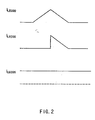
- FIGURE 1 illustrates an embodiment of the invention enabling modulation of the current through less than all of the LEDs supplied by the power converter.
- FIGURE 1 shows input terminals 5 and 10 (advantageously connected to a DC power source) with input terminal 5 , for instance having positive polarity, coupled to inductor 15 that is in turn coupled to the anode of light-emitting diode LED 20 of one primary color, say red. The cathode of LED 20 is then coupled to switch 25 to complete the circuit with negative terminal 10 .
- LED 30 typically but not necessarily providing a different primary color, has its cathode coupled to positive input terminal 5 and its anode coupled to switch 25.
- LED 35 for instance providing the color blue, is coupled directly across input terminals 5 and 10 with its anode coupled to positive terminal 5 and its cathode coupled to negative terminal 10 .
- each LED can, without loss of generality, be replaced by a series or parallel combination of various devices that, in combination, provide similar unidirectional current paths.
- FIGURE 1 operates as described next.
- Switch 25 turns on and off at a high frequency.
- switch 25 When switch 25 is turned on, current rises for a time-period with the same current flowing through LED 20 .
- switch 25 When switch 25 is turned off, current through the inductor 25 flows through LED 30 .
- LED 35 being directly connected across the input experiences a constant current flow through it.
- the resulting current waveform for each LED is shown in FIGURE 2 .
- the inductor current does not decrease to zero with the apparatus operating in a continuous mode.
- FIGURE 3 shows the current waveforms corresponding to the continuous mode operation.
- FIGURE 2 Current waveforms in FIGURE 2 show the current through the three LEDs in the discontinuous mode.
- the waveforms are different reflecting the different brightness of each LED.
- a front-end converter or a variable voltage source provides a variable V in for adjusting the relative brightness to produce different colors.
- Current waveforms in FIGURE 3 show the current through the three LEDs in the continuous mode.
- the current ratio can be adjusted by the duty cycle. This can be coordinated with a variable input voltage enables further color variation.
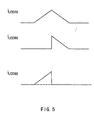
- FIGURE 4 illustrates an alternative embodiment that enables modulation of the current through all of the depicted LEDs.
- the embodiment of FIGURE 1 depicts one of the LEDs as directly coupled to the input power source and limited input voltage range. In the embodiment shown in FIGURE 4 , this constraint is removed since the third LED is arranged in series with the input power source resulting in control over the current through all LEDs.
- FIGURE 4 illustrates, in part, a pair of input terminals 50 and 55 coupled to a DC source. Positive terminal 50 is coupled to the anode of LED 60 with its cathode coupled to inductor 65 that is further coupled to the anode of LED 70 producing another color.
- LED 70 has its cathode coupled to a switch 75 . Next, switch 75 is coupled to negative input terminal 55.
- LED 80 capable of producing yet another color is coupled in parallel with the series combination of inductor 65 and LED 70.
- FIGURE 4 operates as follows.
- Switch 75 capable of turning on and off at a high frequency, when turned on causes current through inductor 65 to build up.
- switch 75 When the switch 75 is turned off, current through inductor 65 flows through LED 80.
- FIGURE 5 shows current waveforms through the three LEDs in the discontinuous mode. If the inductance of inductor 65 or the switching frequency is high enough, the converter operates in the continuous mode and the corresponding current waveforms are shown in FIGURE 6.
- the three currents through the three LEDs can be varied resulting in controlling the brightness by adjusting the input voltage.
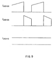
- FIGURE 7 illustrates an alternative embodiment of the invention that allows only two of the three depicted LEDs to emit light at any given time.
- FIGURE 7 illustrates a pair of input terminals 100 and 105 for connecting to a DC power source.
- LED 110 is coupled directly across the positive and negative input terminals.
- LED 110 has brightness dependent on the input voltage and the inherent device characteristic.
- An inductor 115 coupled to positive terminal 100 is further coupled to the anode of LEDs 120 and 125.
- LED 120 has its cathode coupled a switch 130 that is further coupled to the negative terminal 105 .
- LED 125 also has its cathode coupled to negative terminal 105.
- LED 125 may be replaced by a plurality of devices connected in series such that the total voltage when activated is higher than the magnitude of the input voltage.
- FIGURE 7 Operation of the embodiment shown in FIGURE 7 is similar to the previously described embodiments. Briefly, high frequency switch 130 turns on resulting in an increase in the current through inductor 115 . When high frequency switch 130 turns off, the inductor 115 causes current to flow through LED 125 . In this embodiment of the invention, the total voltage drop across LED 125 is higher than the input voltage at terminals 100 and 105 . This arrangement decreases the current through LED 125 after switch 130 turns off. LED current waveforms for discontinuous operation are shown in FIGURE 8 . As mentioned previously in the context or other embodiments, if the inductance of inductor 115 or switching frequency of switch 130 is high enough the converter may operate in the continuous mode as is shown in FIGURE 9 .
- FIGURE 10 shows yet another embodiment of the invention that allows the brightness of all the LEDs to be modulated.
- FIGURE 10 enables changing the brightness of all three LEDs.
- FIGURE 10 depicts LED 160 connected in series with the input voltage source to enable control over the current through all of the LEDs as described next.
- FIGURE 10 shows input terminals 150 and 155 connected to a DC source.
- Positive input terminal 150 is coupled to the anode of LED 160 while the cathode of LED 160 is coupled to inductor 165 .
- Inductor 165 is further coupled to cathodes of LEDs 170 and 175 .
- LED 175 is configured such that the total forward voltage is greater than the input voltage plus the forward voltage of LED 160 .
- LED 175 has its cathode coupled to negative input terminal 155 .
- LED 170 has its cathode coupled to a switch 180 which is further coupled to negative input terminal 155.
- FIGURE 10 The embodiment shown in FIGURE 10 is believed to operate as described next.
- high frequency switch 180 turns on current increases through inductor 165 connected in series circuit with LEDs 160 and 170 .
- Turning switch 180 off directs current through inductor 165 and LED 175 .
- Corresponding current waveforms for each of the three depicted LEDs in FIGURE 10 are shown in FIGURE 11 for discontinuous mode operation.
- FIGURE 12 presents exemplary current waveforms corresponding to operations in the continuous mode.
- the current ratios can be varied by the input voltage V in .
- varying the current through each LED 170 , LED 175 and LED 160 allows modulation of its' respective brightness.
- changing the duty cycle D and/or the input voltage enables such modulation.
- the aforementioned four embodiments provide non-isolated configurations for LEDs producing primary colors, although the configurations are suitable for driving LEDs producing other colors as well.
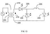
- FIGURE 13 shows an exemplary embodiment of the invention comprising a forward converter.
- FIGURE 13 shows power transformer 200 having primary winding 205 and at least one secondary winding 210 .
- Secondary winding 210 has two terminals 215 and 220 .
- Terminal 215 is connected to the anode of LED 225 while terminal 220 is coupled to the anode of LED 230 .
- the cathodes of LEDs 225 and 230 meet at a node that is further coupled to one end of inductor 235.
- the other end of inductor 235 connects to the cathode of LED 240 that, in turn, connects via its cathode to terminal 220 to complete the circuit.
- Primary winding 205 receives a series of pulses as the primary winding of the transformer of a forward converter, including known forward converters that induce, in response to the pulses at the primary side, alternating voltage pulses at secondary winding 210 .
- terminal 215 becomes positive in polarity. This voltage increases the current through inductor 235 , and LEDs 225 and. 240 .
- terminal 215 has negative polarity and LED 225 is reverse biased. Then, the current through inductor 235 flows through LED 230 instead of LED 225 in a manner similar to the operation of the embodiment of the invention presented in FIGURE 4 .
- each LED 225, 230 or 240 produces one of the three primary colors that in combination produce a desired color.
- Current through any of LEDs 225 , 230 or 240 is modulated to produce a desired brightness with the combination of the three LEDs resulting in a desired color from a broad range of possible colors.
- the duty cycle and the input voltage determine the current through each of the LEDs 225 , 230 or 240 as described previously in the context of FIGURE 4 . With no loss of generality it should be noted that each LED is replaceable by a combination of LEDs or other components producing a similar unidirectional current path.
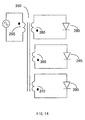
- FIGURE 14 shows another exemplary embodiment of the invention comprising a flyback converter with a coupled inductor 250 .
- Coupled inductor 250 has a primary winding 255, and multiple secondary windings such as the shown secondary windings 265 , 270 and 275 .
- Winding 260 is coupled to LED 280
- winding 265 is coupled to LED 285
- winding 270 is coupled to LED 290.
- each of the LEDs 280, 285, and 290 produce one of the three primary colors that are combined to generate a desired color.
- the number of secondary windings can be further varied according to the number of colors required or LEDs driven by the common power converter.
- FIGURE 14 Operation of the embodiment of the invention in FIGURE 14 is described next with primary winding 255 coupled to a series of alternating square voltage pulses.
- This apparatus operates as a flyback converter such that when primary winding 255 is energized, LEDs coupled to corresponding secondary windings are reverse biased such that no energy is transferred to them since no current flows through them. When the voltage polarity across winding 255 reverses, energy stored in coupled inductor 250 is released to each LED. In practice this type of converter typically operates in the discontinuous mode when coupled to a front end AC to DC diode-bridge.
- a series of suitable alternating square voltage pulse for primary winding 255 enable the current drawn from the AC source to follow the alternating voltage to obtain a high power factor.
- Brightness of the LEDs can be varied to create different colors combinations as described previously with the currents through the various LEDs depending on the number of turns of the associated secondary winding and the duty cycle.
- FIGURE 15 shows another illustrative embodiment of the invention employing a center-tapped transformer.
- Illustrated center-tapped converter comprises transformer 300 with a primary winding 305 , and secondary windings 310 and 315 coupled together at a node.
- Secondary winding 310 is coupled to the anode of LED 320
- secondary winding 315 is coupled to the anode of LED 325 .
- LEDs 320 and 325 have their cathodes connected together and to one end of inductor 330 .
- LED 335 has its anode coupled to inductor 330 and its cathode coupled to the node joining secondary windings 310 and 315.
- LEDs 315, 320 and 335 emit light of different colors to enable generation of additional colors by combining their respective emissions.
- Primary winding 305 possibly driven by half bridge circuits or full bridge circuits like most forward converters, receives a series of voltage pulses resulting in energizing secondary windings 310 and 315 .
- Current from secondary windings 310 and 315 flows to inductor 330 via either LED 320 or LED 325 and then to LED 335 .
- the current through the each of LEDs 320 , 325 and 335 is modulated by varying the ratio of secondary and primary windings, switching frequency, duty cycle, the input voltage, and the value of inductor 330 .
- suitably adjusting the current through an LED results in producing a desired brightness and in combination with the color produced by other LEDs generates a desired color.
- FIGURES 13-15 include an alternating power source, this is not intended to indicate sinusoidal alternating power sources only. Indeed square waves or even irregular waveforms capable of driving the secondary windings are intended to be included by the illustrative depiction of an alternating power source.
- the alternating power source includes one or more of a switching forward power converter, a transformer, a switching flyback power converter, a switching bridge power converter, and the like.
- the aforementioned embodiments include an inductor coupled in series with a first LED with a second light emitting diode coupled in parallel to the inductor and the first LED.
- the second LED is oriented so that it is reverse biased when a power source drives a current through the inductor and the first LED.
- a switch controls the connection of the inductor and the first LED to the power source.
- additional LEDs can be added, for instance a third LED coupled, in parallel to the first light emitting diode, to a first terminal and a second terminal of the power source.
- a third light emitting diode is coupled in series to the first light emitting diode and to a first terminal and a second terminal of the power source.
- Another embodiment comprises an inductor coupled in series with a first LED, a switch controlling a connection of the inductor and the first LED to a power source, in turn, connected in series to the inductor via the switch and a second LED.
- the second LED has a forward voltage higher than input voltage across the power source and is connected in parallel to the switch and the first LED.
- the second LED is coupled in series with the inductor and the power source.
- additional LEDs can be added, for instance, by using a bank of LEDs instead of a single LED or, for instance, a third light emitting diode coupled in parallel to the first and second input terminals of the power source.
- the third light emitting diode can also be coupled in series with the first or second terminals of the power source.
- An example apparatus includes a switching forward power converter with a transformer, a secondary winding coupled to the transformer, an LED coupled to the secondary winding and an inductor. Another LED is also connected to the inductor and another terminal of the secondary winding with a third LED coupled in parallel with the series combination of the second light emitting diode and the inductor. The operation of the configuration is as described for FIGURES 13-15.
- Another isolation providing design uses a switching flyback power converter, a transformer, a plurality of secondary windings coupled to the transformer, and an LED coupled to the secondary windings.
- the apparatus can incorporate a bridge rectifier for converting an alternating current to a direct current with means to operate the flyback converter to operate in discontinuous mode with current delivered by an alternating current source with phase angle following a corresponding alternating voltage.
- the input current is proportional to the input voltage making the converter input impedance resistive. If the input voltage is derived from a bridge rectifier driven by a sinusoidal voltage then the input current will also be sinusoidal in phase with the driving voltage. The resulting output LED currents may also be sinusoidal but their brightness variation at line frequency will not be perceived by human eye.
- Yet another configuration comprises a switching bridge power converter, a transformer, two or more secondary windings such that a first terminal of the first secondary winding has the opposite polarity to that of a first terminal of the second secondary winding.
- Two LEDs coupled together at their cathodes, are connected to an inductor.
- the anode of the first light emitting diode is connected to the first terminal of the first secondary winding and the anode of the second light emitting diode being connected to the first terminal of the second secondary winding.
- the inductor coupled to the cathodes of the LEDs is further coupled to a second terminal of the first secondary winding and a second terminal of the second secondary winding via a third light emitting diode.
Landscapes
- Circuit Arrangement For Electric Light Sources In General (AREA)
- Led Devices (AREA)
- Control Of Indicators Other Than Cathode Ray Tubes (AREA)
Applications Claiming Priority (2)
| Application Number | Priority Date | Filing Date | Title |
|---|---|---|---|
| US10/017,661 US7178971B2 (en) | 2001-12-14 | 2001-12-14 | High efficiency driver for color light emitting diodes (LED) |
| US17661 | 2001-12-14 |
Publications (3)
| Publication Number | Publication Date |
|---|---|
| EP1320284A2 true EP1320284A2 (fr) | 2003-06-18 |
| EP1320284A3 EP1320284A3 (fr) | 2005-01-19 |
| EP1320284B1 EP1320284B1 (fr) | 2007-07-25 |
Family
ID=21783850
Family Applications (1)
| Application Number | Title | Priority Date | Filing Date |
|---|---|---|---|
| EP02027332A Expired - Lifetime EP1320284B1 (fr) | 2001-12-14 | 2002-12-07 | Circuit de commande à haut rendement pour Leds de couleur |
Country Status (6)
| Country | Link |
|---|---|
| US (2) | US7178971B2 (fr) |
| EP (1) | EP1320284B1 (fr) |
| CN (1) | CN1287642C (fr) |
| DE (1) | DE60221343T2 (fr) |
| HK (1) | HK1054485B (fr) |
| TW (1) | TWI278812B (fr) |
Cited By (13)
| Publication number | Priority date | Publication date | Assignee | Title |
|---|---|---|---|---|
| WO2005048658A1 (fr) * | 2003-11-13 | 2005-05-26 | Philips Intellectual Property & Standards Gmbh | Circuit resonnant de commande de diodes electroluminescentes de puissance pour le reglage de la luminosite et de la saturation des couleurs |
| DE102004047681A1 (de) * | 2004-09-30 | 2006-04-13 | Osram Opto Semiconductors Gmbh | LED-Schaltungsanordnung mit einem Diodengleichrichter |
| GB2420613A (en) * | 2004-08-27 | 2006-05-31 | Bespoke Lighting Ltd | Lighting |
| WO2007125466A1 (fr) | 2006-05-02 | 2007-11-08 | Philips Intellectual Property & Standards Gmbh | Circuit a diodes lumineuses, et montage et dispositif associes |
| WO2008041153A1 (fr) * | 2006-10-06 | 2008-04-10 | Philips Intellectual Property & Standards Gmbh | Dispositif d'alimentation électrique pour éléments lumineux et procédé d'alimentation d'éléments lumineux |
| CN101686591A (zh) * | 2008-09-09 | 2010-03-31 | 艾斯克拉克公司 | 用于供电至固态照明的装置、方法及系统 |
| US8035313B2 (en) | 2006-10-06 | 2011-10-11 | Koninklijke Philips Electronics N.V. | Light element array with controllable current sources and method of operation |
| US8106599B2 (en) | 2006-10-06 | 2012-01-31 | Koninklijke Philips Electronics N.V. | Switched light element array and method of operation |
| DE102010038787A1 (de) * | 2010-08-02 | 2012-02-02 | Osram Ag | Schaltungsanordnung und Verfahren zum Betreiben mindestens einer ersten und mindestens einer zweiten Led |
| AT511990A1 (de) * | 2011-09-27 | 2013-04-15 | Fachhochschule Technikum Wien | Stellglied zur ansteuerung von lichtemittierenden dioden |
| US8536796B2 (en) | 2008-10-21 | 2013-09-17 | Koninklijke Philips N.V. | Light emitting diode driving apparatus |
| WO2019219518A1 (fr) | 2018-05-15 | 2019-11-21 | Signify Holding B.V. | Circuit d'éclairage et procédé de commande |
| EP3592112A1 (fr) * | 2018-07-02 | 2020-01-08 | Signify Holding B.V. | Circuit d'éclairage et procédé de commande |
Families Citing this family (37)
| Publication number | Priority date | Publication date | Assignee | Title |
|---|---|---|---|---|
| CN1653297B (zh) * | 2002-05-08 | 2010-09-29 | 佛森技术公司 | 高效固态光源及其使用和制造方法 |
| WO2005009086A1 (fr) * | 2003-07-16 | 2005-01-27 | Koninklijke Philips Electronics N.V. | Procede et dispositif d'alimentation de diodes electroluminescentes |
| US7256554B2 (en) * | 2004-03-15 | 2007-08-14 | Color Kinetics Incorporated | LED power control methods and apparatus |
| US7633463B2 (en) | 2004-04-30 | 2009-12-15 | Analog Devices, Inc. | Method and IC driver for series connected R, G, B LEDs |
| TWI413445B (zh) * | 2004-06-03 | 2013-10-21 | Koninkl Philips Electronics Nv | 照明電路 |
| EP1820371A1 (fr) * | 2004-11-29 | 2007-08-22 | Koninklijke Philips Electronics N.V. | Procede et circuit de commande de fonctionnement d'une del |
| DE102005030114A1 (de) * | 2005-06-28 | 2007-01-18 | Patent-Treuhand-Gesellschaft für elektrische Glühlampen mbH | Schaltungsanordnung und Verfahren zum Betrieb mindestens einer elektrischen Lampe und mindestens einer LED |
| US7438442B2 (en) * | 2005-10-12 | 2008-10-21 | Lg Display Co., Ltd. | Light emitting package, backlight unit and liquid crystal display device including the same |
| US7741825B2 (en) * | 2006-11-02 | 2010-06-22 | Infineon Technologies Ag | Power supply circuit with temperature-dependent drive signal |
| US20080231204A1 (en) * | 2007-03-19 | 2008-09-25 | Praiswater Michael R | Light emitting diode assembly replacement for fluorescent lamp |
| US7772782B2 (en) * | 2007-12-05 | 2010-08-10 | Leadtrend Technology Corp. | Light emitting diode (LED) driving device |
| TWM346239U (en) * | 2008-07-16 | 2008-12-01 | Gigno Technology Co Ltd | Driving device of lighting apparatus |
| EP2345307B1 (fr) * | 2008-10-10 | 2013-12-11 | Koninklijke Philips N.V. | Procédés et appareil pour commander des sources lumineuses multiples par l intermédiaire d un circuit régulateur simple pour fournir une lumière de couleur et/ou de température de couleur variables |
| US8427063B2 (en) * | 2009-07-29 | 2013-04-23 | Vektrex Electronic Systems, Inc. | Multicolor LED sequencer |
| TWI538553B (zh) | 2009-08-25 | 2016-06-11 | 皇家飛利浦電子股份有限公司 | 多通道照明單元及供應電流至其光源之驅動器 |
| TWI416989B (zh) * | 2009-09-18 | 2013-11-21 | Richtek Technology Corp | 發光元件控制電路與控制方法、及用於其中的積體電路 |
| US8872439B2 (en) | 2010-04-30 | 2014-10-28 | Texas Instruments Incorporated | System and methods for providing equal currents to current driven loads |
| US20120119676A1 (en) * | 2010-11-15 | 2012-05-17 | Power Integrations, Inc. | Flyback power converter with divided energy transfer element |
| US20120146536A1 (en) * | 2010-12-13 | 2012-06-14 | Nate Mullen | Led lighting system |
| US9420240B2 (en) | 2011-05-15 | 2016-08-16 | Lighting Science Group Corporation | Intelligent security light and associated methods |
| US8674608B2 (en) | 2011-05-15 | 2014-03-18 | Lighting Science Group Corporation | Configurable environmental condition sensing luminaire, system and associated methods |
| US8729832B2 (en) | 2011-05-15 | 2014-05-20 | Lighting Science Group Corporation | Programmable luminaire system |
| US9648284B2 (en) | 2011-05-15 | 2017-05-09 | Lighting Science Group Corporation | Occupancy sensor and associated methods |
| US9185783B2 (en) | 2011-05-15 | 2015-11-10 | Lighting Science Group Corporation | Wireless pairing system and associated methods |
| TWI442811B (zh) | 2011-05-27 | 2014-06-21 | Ind Tech Res Inst | 光源驅動裝置 |
| US8492995B2 (en) | 2011-10-07 | 2013-07-23 | Environmental Light Technologies Corp. | Wavelength sensing lighting system and associated methods |
| US8515289B2 (en) | 2011-11-21 | 2013-08-20 | Environmental Light Technologies Corp. | Wavelength sensing lighting system and associated methods for national security application |
| US9402294B2 (en) | 2012-05-08 | 2016-07-26 | Lighting Science Group Corporation | Self-calibrating multi-directional security luminaire and associated methods |
| US8680457B2 (en) | 2012-05-07 | 2014-03-25 | Lighting Science Group Corporation | Motion detection system and associated methods having at least one LED of second set of LEDs to vary its voltage |
| US9006987B2 (en) | 2012-05-07 | 2015-04-14 | Lighting Science Group, Inc. | Wall-mountable luminaire and associated systems and methods |
| US9174067B2 (en) | 2012-10-15 | 2015-11-03 | Biological Illumination, Llc | System for treating light treatable conditions and associated methods |
| US9303825B2 (en) | 2013-03-05 | 2016-04-05 | Lighting Science Group, Corporation | High bay luminaire |
| JP6145821B2 (ja) * | 2013-09-13 | 2017-06-14 | パナソニックIpマネジメント株式会社 | 照明用光源及び照明装置 |
| TWI563216B (en) * | 2014-08-22 | 2016-12-21 | Lite On Electronics Guangzhou | Light-emitting device |
| US9900945B1 (en) * | 2015-05-01 | 2018-02-20 | Cooper Technologies Company | Color temperature control |
| TW201914717A (zh) * | 2017-09-29 | 2019-04-16 | 美商科斯莫燈飾公司 | 電線、剝線方法以及燈具 |
| TWI667941B (zh) * | 2018-07-16 | 2019-08-01 | 林再福 | High-efficiency color LED lamp shared drive |
Citations (3)
| Publication number | Priority date | Publication date | Assignee | Title |
|---|---|---|---|---|
| JPS6053090A (ja) * | 1983-09-02 | 1985-03-26 | Mayumi Watanabe | Ledの点灯装置 |
| JPS61196586A (ja) * | 1985-02-26 | 1986-08-30 | Mitsubishi Electric Corp | 発光ダイオ−ド駆動回路 |
| EP0950342A1 (fr) * | 1997-01-03 | 1999-10-20 | Telefonaktiebolaget Lm Ericsson | Circuit de commande et procede permettant de le faire fonctionner |
Family Cites Families (19)
| Publication number | Priority date | Publication date | Assignee | Title |
|---|---|---|---|---|
| US4436960A (en) * | 1982-01-11 | 1984-03-13 | Bell Telephone Laboratories, Incorporated | Telephone ringing signal generator |
| US4496939A (en) * | 1982-06-04 | 1985-01-29 | Eastman Kodak Company | Power indicator apparatus for a DC to DC flyback converter |
| US6069412A (en) * | 1993-03-29 | 2000-05-30 | Powerware Corporation | Power factor corrected UPS with improved connection of battery to neutral |
| FR2762721B1 (fr) * | 1997-04-29 | 1999-06-11 | Sagem | Procede de charge d'une batterie et chargeur de batterie pour la mise en oeuvre du procede |
| JPH1169814A (ja) * | 1997-08-14 | 1999-03-09 | Toshiba Corp | 電源装置およびその並列運転制御回路 |
| US6072280A (en) * | 1998-08-28 | 2000-06-06 | Fiber Optic Designs, Inc. | Led light string employing series-parallel block coupling |
| FI106770B (fi) * | 1999-01-22 | 2001-03-30 | Nokia Mobile Phones Ltd | Valaiseva elektroninen laite ja valaisumenetelmä |
| JP3494403B2 (ja) * | 1999-01-27 | 2004-02-09 | Tdk株式会社 | スイッチング電源 |
| US6371637B1 (en) * | 1999-02-26 | 2002-04-16 | Radiantz, Inc. | Compact, flexible, LED array |
| US6243276B1 (en) * | 1999-05-07 | 2001-06-05 | S-B Power Tool Company | Power supply system for battery operated devices |
| AU1889201A (en) * | 1999-12-14 | 2001-06-25 | Takion Co., Ltd. | Power supply and led lamp device |
| JP3317950B2 (ja) * | 2000-01-24 | 2002-08-26 | 甲府日本電気株式会社 | アクティブクランプフォアワードコンバータ |
| US6388393B1 (en) * | 2000-03-16 | 2002-05-14 | Avionic Instruments Inc. | Ballasts for operating light emitting diodes in AC circuits |
| US6333861B1 (en) * | 2000-06-06 | 2001-12-25 | Astec International Limited | Low loss snubber and transformer reset circuit for forward converters |
| US6369525B1 (en) * | 2000-11-21 | 2002-04-09 | Philips Electronics North America | White light-emitting-diode lamp driver based on multiple output converter with output current mode control |
| US6888529B2 (en) * | 2000-12-12 | 2005-05-03 | Koninklijke Philips Electronics N.V. | Control and drive circuit arrangement for illumination performance enhancement with LED light sources |
| US6359392B1 (en) * | 2001-01-04 | 2002-03-19 | Motorola, Inc. | High efficiency LED driver |
| US6577512B2 (en) * | 2001-05-25 | 2003-06-10 | Koninklijke Philips Electronics N.V. | Power supply for LEDs |
| US6646895B1 (en) * | 2001-10-25 | 2003-11-11 | Tyco Electronics Power Systems, Inc. | Bias supply circuit and a switching power supply employing the same |
-
2001
- 2001-12-14 US US10/017,661 patent/US7178971B2/en not_active Expired - Lifetime
-
2002
- 2002-12-07 EP EP02027332A patent/EP1320284B1/fr not_active Expired - Lifetime
- 2002-12-07 DE DE60221343T patent/DE60221343T2/de not_active Expired - Lifetime
- 2002-12-14 CN CNB021574138A patent/CN1287642C/zh not_active Expired - Lifetime
- 2002-12-16 TW TW091136255A patent/TWI278812B/zh not_active IP Right Cessation
-
2003
- 2003-09-19 HK HK03106744.3A patent/HK1054485B/zh not_active IP Right Cessation
-
2006
- 2006-10-24 US US11/585,178 patent/US7567040B2/en not_active Expired - Lifetime
Patent Citations (3)
| Publication number | Priority date | Publication date | Assignee | Title |
|---|---|---|---|---|
| JPS6053090A (ja) * | 1983-09-02 | 1985-03-26 | Mayumi Watanabe | Ledの点灯装置 |
| JPS61196586A (ja) * | 1985-02-26 | 1986-08-30 | Mitsubishi Electric Corp | 発光ダイオ−ド駆動回路 |
| EP0950342A1 (fr) * | 1997-01-03 | 1999-10-20 | Telefonaktiebolaget Lm Ericsson | Circuit de commande et procede permettant de le faire fonctionner |
Non-Patent Citations (3)
| Title |
|---|
| "DRIVER FOR SUPPLYING A PULSATING CURRENT TO LIGHT EMITTING DIODES" RESEARCH DISCLOSURE, KENNETH MASON PUBLICATIONS, HAMPSHIRE, GB, no. 378, 1 October 1995 (1995-10-01), page 651, XP000549126 ISSN: 0374-4353 * |
| PATENT ABSTRACTS OF JAPAN vol. 0091, no. 81 (E-331), 26 July 1985 (1985-07-26) & JP 60 053090 A (MAYUMI WATANABE), 26 March 1985 (1985-03-26) * |
| PATENT ABSTRACTS OF JAPAN vol. 0110, no. 27 (E-474), 27 January 1987 (1987-01-27) & JP 61 196586 A (MITSUBISHI ELECTRIC CORP), 30 August 1986 (1986-08-30) * |
Cited By (26)
| Publication number | Priority date | Publication date | Assignee | Title |
|---|---|---|---|---|
| JP2007511903A (ja) * | 2003-11-13 | 2007-05-10 | コーニンクレッカ フィリップス エレクトロニクス エヌ ヴィ | 輝度および色調の調整を伴う共振型パワーled制御回路 |
| WO2005048658A1 (fr) * | 2003-11-13 | 2005-05-26 | Philips Intellectual Property & Standards Gmbh | Circuit resonnant de commande de diodes electroluminescentes de puissance pour le reglage de la luminosite et de la saturation des couleurs |
| CN1879453B (zh) * | 2003-11-13 | 2010-06-23 | 皇家飞利浦电子股份有限公司 | 具有亮度和颜色控制的谐振电源led控制电路 |
| GB2420613A (en) * | 2004-08-27 | 2006-05-31 | Bespoke Lighting Ltd | Lighting |
| US7808189B2 (en) | 2004-09-30 | 2010-10-05 | Osram Opto Semiconductors Gmbh | LED circuit arrangement having a diode rectifier |
| DE102004047681A1 (de) * | 2004-09-30 | 2006-04-13 | Osram Opto Semiconductors Gmbh | LED-Schaltungsanordnung mit einem Diodengleichrichter |
| DE102004047681B4 (de) * | 2004-09-30 | 2009-01-02 | Osram Opto Semiconductors Gmbh | LED-Schaltungsanordnung mit einem Diodengleichrichter |
| WO2007125466A1 (fr) | 2006-05-02 | 2007-11-08 | Philips Intellectual Property & Standards Gmbh | Circuit a diodes lumineuses, et montage et dispositif associes |
| US8076872B2 (en) | 2006-05-02 | 2011-12-13 | Koninklijke Philips Electronics N.V. | Light emitting diode circuit and arrangement and device |
| US8067898B2 (en) | 2006-10-06 | 2011-11-29 | Koninklijke Philips Electronics N.V. | Power supply device for light elements and method for supplying power to light elements |
| WO2008041153A1 (fr) * | 2006-10-06 | 2008-04-10 | Philips Intellectual Property & Standards Gmbh | Dispositif d'alimentation électrique pour éléments lumineux et procédé d'alimentation d'éléments lumineux |
| US8035313B2 (en) | 2006-10-06 | 2011-10-11 | Koninklijke Philips Electronics N.V. | Light element array with controllable current sources and method of operation |
| US8106599B2 (en) | 2006-10-06 | 2012-01-31 | Koninklijke Philips Electronics N.V. | Switched light element array and method of operation |
| US9408259B2 (en) | 2008-09-09 | 2016-08-02 | Chemtron Research Llc | Apparatus and system for providing power to solid state lighting |
| CN101686591A (zh) * | 2008-09-09 | 2010-03-31 | 艾斯克拉克公司 | 用于供电至固态照明的装置、方法及系统 |
| US8242704B2 (en) | 2008-09-09 | 2012-08-14 | Point Somee Limited Liability Company | Apparatus, method and system for providing power to solid state lighting |
| US8742679B2 (en) | 2008-09-09 | 2014-06-03 | Point Somee Limited Liability Company | Apparatus and system for providing power to solid state lighting |
| CN101686591B (zh) * | 2008-09-09 | 2014-06-04 | 普英森亿有限责任公司 | 用于供电至固态照明的装置、方法及系统 |
| EP2161969A3 (fr) * | 2008-09-09 | 2011-09-14 | Exclara, Inc. | Appareil, procédé et système d'alimentation pour un éclairage semi-conducteur |
| US9894730B2 (en) | 2008-09-09 | 2018-02-13 | Chemtron Research Llc | Apparatus and system for providing power to solid state lighting |
| US8536796B2 (en) | 2008-10-21 | 2013-09-17 | Koninklijke Philips N.V. | Light emitting diode driving apparatus |
| DE102010038787A1 (de) * | 2010-08-02 | 2012-02-02 | Osram Ag | Schaltungsanordnung und Verfahren zum Betreiben mindestens einer ersten und mindestens einer zweiten Led |
| AT511990A1 (de) * | 2011-09-27 | 2013-04-15 | Fachhochschule Technikum Wien | Stellglied zur ansteuerung von lichtemittierenden dioden |
| AT511990B1 (de) * | 2011-09-27 | 2013-06-15 | Fachhochschule Technikum Wien | Stellglied zur ansteuerung von lichtemittierenden dioden |
| WO2019219518A1 (fr) | 2018-05-15 | 2019-11-21 | Signify Holding B.V. | Circuit d'éclairage et procédé de commande |
| EP3592112A1 (fr) * | 2018-07-02 | 2020-01-08 | Signify Holding B.V. | Circuit d'éclairage et procédé de commande |
Also Published As
| Publication number | Publication date |
|---|---|
| US7567040B2 (en) | 2009-07-28 |
| HK1054485B (zh) | 2007-07-13 |
| TWI278812B (en) | 2007-04-11 |
| EP1320284B1 (fr) | 2007-07-25 |
| DE60221343D1 (de) | 2007-09-06 |
| TW200411614A (en) | 2004-07-01 |
| US20070040514A1 (en) | 2007-02-22 |
| DE60221343T2 (de) | 2008-04-17 |
| EP1320284A3 (fr) | 2005-01-19 |
| CN1287642C (zh) | 2006-11-29 |
| US20030112229A1 (en) | 2003-06-19 |
| US7178971B2 (en) | 2007-02-20 |
| HK1054485A1 (en) | 2003-11-28 |
| CN1426270A (zh) | 2003-06-25 |
Similar Documents
| Publication | Publication Date | Title |
|---|---|---|
| US7178971B2 (en) | High efficiency driver for color light emitting diodes (LED) | |
| EP1685745B1 (fr) | Circuit resonnant de commande de diodes electroluminescentes de puissance pour le reglage de la luminosite et de la saturation des couleurs | |
| US9000673B2 (en) | Multi-channel two-stage controllable constant current source and illumination source | |
| US8598807B2 (en) | Multi-channel constant current source and illumination source | |
| JP4934508B2 (ja) | Ledを備えたlcdバックライトの駆動システム | |
| EP2770623B1 (fr) | Convertisseur résonant | |
| US8063577B2 (en) | Method and a driver circuit for LED operation | |
| JP5471752B2 (ja) | Led駆動装置 | |
| KR100833986B1 (ko) | 다상 전압 소스 구동 에이씨-엘이디 | |
| JP2010035270A (ja) | 電力変換装置 | |
| JP2010035271A (ja) | 電力変換装置 | |
| TW200809756A (en) | Liquid crystal display backlight driving system with light emitting diodes | |
| EP2916621A2 (fr) | Techniques de commande de gradation hybride pour des pilotes d'éclairage | |
| JP2007265806A (ja) | 照明装置 | |
| US9445472B2 (en) | Method and circuit for driving light-emitting diodes from three-phase power source | |
| JP4472640B2 (ja) | 発光ダイオード定電流駆動回路 | |
| JPH10321914A (ja) | 発光装置及びこの発光装置を使用した照明装置 | |
| US20130043808A1 (en) | Multi-channel led driver circuit | |
| JP2007189027A (ja) | 発光ダイオード定電流駆動回路 | |
| KR101279272B1 (ko) | 플라이 백 동작을 수행하는 조명장치 | |
| JP2020510298A (ja) | Led構成及びled駆動方法 | |
| TW201125252A (en) | Balanced current circuit. |
Legal Events
| Date | Code | Title | Description |
|---|---|---|---|
| PUAI | Public reference made under article 153(3) epc to a published international application that has entered the european phase |
Free format text: ORIGINAL CODE: 0009012 |
|
| AK | Designated contracting states |
Designated state(s): AT BE BG CH CY CZ DE DK EE ES FI FR GB GR IE IT LI LU MC NL PT SE SI SK TR |
|
| AX | Request for extension of the european patent |
Extension state: AL LT LV MK RO |
|
| PUAL | Search report despatched |
Free format text: ORIGINAL CODE: 0009013 |
|
| AK | Designated contracting states |
Kind code of ref document: A3 Designated state(s): AT BE BG CH CY CZ DE DK EE ES FI FR GB GR IE IT LI LU MC NL PT SE SI SK TR |
|
| AX | Request for extension of the european patent |
Extension state: AL LT LV MK RO |
|
| 17P | Request for examination filed |
Effective date: 20050215 |
|
| AKX | Designation fees paid |
Designated state(s): DE FR GB |
|
| GRAP | Despatch of communication of intention to grant a patent |
Free format text: ORIGINAL CODE: EPIDOSNIGR1 |
|
| GRAS | Grant fee paid |
Free format text: ORIGINAL CODE: EPIDOSNIGR3 |
|
| GRAA | (expected) grant |
Free format text: ORIGINAL CODE: 0009210 |
|
| AK | Designated contracting states |
Kind code of ref document: B1 Designated state(s): DE FR GB |
|
| REG | Reference to a national code |
Ref country code: GB Ref legal event code: FG4D |
|
| REF | Corresponds to: |
Ref document number: 60221343 Country of ref document: DE Date of ref document: 20070906 Kind code of ref document: P |
|
| ET | Fr: translation filed | ||
| PLBE | No opposition filed within time limit |
Free format text: ORIGINAL CODE: 0009261 |
|
| STAA | Information on the status of an ep patent application or granted ep patent |
Free format text: STATUS: NO OPPOSITION FILED WITHIN TIME LIMIT |
|
| 26N | No opposition filed |
Effective date: 20080428 |
|
| REG | Reference to a national code |
Ref country code: FR Ref legal event code: PLFP Year of fee payment: 14 |
|
| REG | Reference to a national code |
Ref country code: FR Ref legal event code: PLFP Year of fee payment: 15 |
|
| REG | Reference to a national code |
Ref country code: FR Ref legal event code: PLFP Year of fee payment: 16 |
|
| REG | Reference to a national code |
Ref country code: DE Ref legal event code: R079 Ref document number: 60221343 Country of ref document: DE Free format text: PREVIOUS MAIN CLASS: H05B0033080000 Ipc: H05B0045000000 |
|
| PGFP | Annual fee paid to national office [announced via postgrant information from national office to epo] |
Ref country code: DE Payment date: 20211102 Year of fee payment: 20 Ref country code: GB Payment date: 20211104 Year of fee payment: 20 Ref country code: FR Payment date: 20211115 Year of fee payment: 20 |
|
| REG | Reference to a national code |
Ref country code: DE Ref legal event code: R071 Ref document number: 60221343 Country of ref document: DE |
|
| REG | Reference to a national code |
Ref country code: GB Ref legal event code: PE20 Expiry date: 20221206 |
|
| PG25 | Lapsed in a contracting state [announced via postgrant information from national office to epo] |
Ref country code: GB Free format text: LAPSE BECAUSE OF EXPIRATION OF PROTECTION Effective date: 20221206 |